1
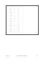
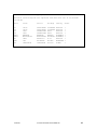
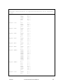
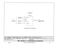
ENSC 204—Assignment SCH1
Introductory Logic Schematic from Netlists
(Read this assignment carefully – before you begin)
DUE
Group Member List (by Email)
CAD Schematic
(General Office hand-in)
24 May 2002 Noon
11 June 2002
OBJECTIVES
To explore simple generic ECAD netlists and learn how they relate to ECAD schematic
symbol interconnection. To familiarize yourself with the selected ECAD software
working environment, and to develop some basic skills in completing a simple logic
schematic. Specific attention will be focused on using Nets, Busses, Net Labels,
junctions, parts placement and arrangement, symbol orientation and annotations.
Please organize yourselves into groups of 4 and elect a group leader. The leader will
accurately gather the ID #, SFU registration First & Last Name, SFU Email address,
and ENSC Year (1st, 2nd, 3rd or 4th) from each member. Then, on the ENSC204 web
site, http://www.ensc.sfu.ca/people/faculty/dill/COURSES/ENSC204 follow the Group
Registration link and complete the table. Do this before the specified due date. Your
Group Number and member list will be posted here within a few days – please look for it.
ASSIGNMENT TASK DISTRIBUTION & RESPONSIBILITIES
A group-appointed leader will organize and divide the tasks and co-ordinate the group's
efforts throughout this assignment. This person will become the primary
representative between your group and the instructor(s) and will be responsible for
ensuring that the assignment is complete and handed in on time. This is a role of
responsibility, intended to develop interpersonal as well as time and task management
skills that will prove a valuable learning experience for future engineering courses and
the real world.
Each group member must complete a fair and equal portion of every aspect of this
assignment and should make an effort to develop skills in areas of non-familiarity in
order to gain a comfortable understanding of the subject matter, concepts and tools
used. In this case, try to work on weaknesses, not just strengths.
* When students work in groups, there's always a tendency for those with strong skill
sets in a particular area to do all the work for that portion of the assignment just to
get it done as quickly as possible. This only serves to exclude the lesser-skilled
partners and hinder their development. Please try not to let this happen in your group.
10/05/02
fred/204-02/ASGN-SCH1 2002R1.doc
1
IMPORTANT GENERAL COMMENTS FOR THIS ASSIGNMENT
Lab Journal: Please note that although ENSC 204 is not designated as a 'Lab Course'
per se, the activities you will be performing in this assignment are lab related.
Therefore, all notes, calculations, sketches should be maintained in your lab journal. If
you choose to work with loose pages, these should be maintained in a manner such that
all project-group information remains together (a binder or similar). Be sure that all
pages are appropriately organized and referenced with the date, author's name,
group number, and topic/project title.
Common Schedule & Learning Support: To ensure that all group members have an equal
opportunity to perform and maintain continuity with all aspects of this assignment, your
group should arrange a common time block, between 0830 and 1600 (Mon.-Fri.) when
your group could meet at a prearranged location in LAB-1. In this way, the instructors
supporting this assignment can be approached for assistance if needed.
As instructors, we are sensitive the fact that you’ll be struggling with a lot of new and
potentially challenging concepts and possibly quite foreign software. Obviously, we wish
to see you sort out the bulk of the problems you encounter as best you can using the
reference materials available (Lab Handbook, handouts, tutorial guides, and the wealth
of stuff available on the Cadsoft website – www.cadsoftusa.com ). If you find that you
are stuck or spending an unreasonable amount of time on any portion, please contact one
of the instructors for guidance or advise them of your difficulty before due deadline.
Current Revisions: Although you should try to accomplish most of the assignment
stages together as a group (or sub-group), this may not always be possible. Agree on a
file naming convention for each assignment and its revision levels for your work files.
Use Email attachments to share your current revisions with the other members of your
group. Never leave any work on lab computers – always back-up to floppy or ZIP drives.
SOFTWARE REQUIRED - EAGLE355r3(3) by CadSoft Computer1
ITEMS SUPPLIED
1) Assignment SCH1 instructions
2) Assembled copies of the following files (included within SCH1 instructions)
a) bus-sch1.net – ASCII netlist
b) bus-sch1.pin - ASCII modified netlist (may be useful)
c) bus-sch1part.txt - library part listing
d) bus-sch1_net.scr - Eagle ASCII script file (a variation on the netlist)
1
EAGLE355 is installed on Engineering Science LabNet computers for your convenience. The EAGLE files are
available for download from the ENSC 204 website for those wishing to use this software on their own PC. (You’ll
need the ENSC document 'Getting Started with Cadsoft EAGLE355', filename EAGLESET.pdf). This assignment
need not be accomplished in the lab, but you must use the EAGLE355 software.
10/05/02
fred/204-02/ASGN-SCH1 2002R1.doc
2
e) bus-sch1-block.sch - Eagle schematic block diagram
3) bus-sch1-parts.sch - Eagle schematic providing the unconnected parts
4) tutorial-eng.pdf - Eagle tutorial
5) MC74HC4351N.pdf - datasheet (if needed)
* (2a-e) & (3 – reference only) are part of this document, (3 - 5) are separate files
available on the ENSC204 Website.
DETAILED INSTRUCTIONS
* For private PC users - Before commencing, it is expected that you have downloaded or
acquired the needed support files for EAGLE355R33 and have installed and configured
EAGLE to suit the recommended preferences. (The steps for accomplishing this are
given in the document 'Getting Started with Cadsoft EAGLE355', EAGLESET.pdf).
1) Print the working pages of this assignment (pgs 1-14).
2) Print optional items (4) & (5) as previously defined.
3) When steps 1 and 2 are completed, you're almost ready to begin. Start EAGLE.
FILE⇒OPEN⇒SCHEMATIC⇒<bus-sch1-parts.sch> (part of the emailed file set – or
from ENSC204 website). This drawing contains the frame/border and document
field as well as an array of unconnected schematic symbols. Use FILE⇒SAVE_AS
to save this file into your project target directory2, using the file naming format
<(group# 2digits)+'SCH1'> eg '05SCH1'. So far so good???
Now for the tougher part...
…to create a representative ECAD schematic from the given netlist.
Using the printouts you've assembled, determine a reasonable starting arrangement for
the parts on the screen. (You'll likely change and reorganize these a few times as the
drawing takes shape). Examine the Netlist and draw NETs between the symbols. It's
recommended that you carefully study the Netlist printout before getting too involved.
Then try to attack the bulk stuff first by determining single parts that have multiple
pin interconnections and connect them up using the NET and BUS commands. Cross off
the nets on the printout as you complete them.
An array of Power and Ground symbols are supplied on the drawing sheet for your
convenience. If you have any extras after you've got everything neatly connected
exactly in the way want them, you may delete them - try not to be too hasty - else you’ll
be burning your valuable time hunting through all the libraries to find the replacements!
2
For personal PC users, work out of …EAGLE/Projects/204SCH1. For LabNet users work out of C:\temp, making
certain to back this up regularly to your diskette in drive A:.
10/05/02
fred/204-02/ASGN-SCH1 2002R1.doc
3
(Source libraries are given in file BUS-SCH1PART.txt. Power symbols are in the
FSupply.lbr. Deleted symbols can be reinserted using the ADD command. ***For this
assignment, you shouldn’t need to add extra symbols to the drawing sheet***).
General design rules to note:
a) Connectors like HDR1 shall be placed with their pin orientation arranged in the
same manner in which it would appear in the physical part or assembly – in this
case, pin 1 = top left (as given). This is a standard practice to avoid confusion.
b) Component pin swapping is not permitted in this exercise.
You may find it somewhat beneficial to open the example schematics that come with
EAGLE (look in your Eagle directory for subfolder 'Examples'). These illustrate how
busses may be used. Don't study these too carefully, they're not perfect and still use
some symbols which are flawed (these schematics haven't been altered since their
creation in the early days of EAGLE) - the rest of 355R33 is just fine and has no bugs,
errors or stability problems.
Use the HELP option on EAGLE's top menu row to determine how to define busses. One
of the objectives of this assignment is to use busses where applicable to simplify and
clarify the path of related signals. Be sure to LABEL all signals and busses unless their
function/name is clearly implied to the reader.
To print EAGLE files: File⇒Print. Settings; scale factor ≥2, page limit=1, sheets=1/1,
rotate, black, solid.
**** Always save & make backups – frequently! ****
WHAT TO HAND IN
*** In a reusable, sealable folder of your choice bearing your group # boldly in front
1) A printout of your finished ECAD schematic (in landscape format).
2) A 1.44MB diskette
a) containing your final schematic file only in a directory folder named 204SCH1.
Be sure to use the file naming format <group# (2digits)+'SCH1'> eg '05SCH1'.
b) containing a folder named MEMBERS. With a text editor (ASCII format)
create a file containing the group number and the names, student numbers and
email addresses of your group members.
c) with its contents verified to be virus free!!!!
d) labeled with your group number and ‘ENSC 204 Summer 2002’.
Resubmissions: If you are requested to correct aspects of your work for resubmission,
save your file into the appropriate folder on your diskette and name the file – <Group # (2
digits)>+<SCH1>+<R>+<revision #> eg. 05SCH1R2. Keep your original file(s) intact, making
no further changes to it.
10/05/02
fred/204-02/ASGN-SCH1 2002R1.doc
4
OPTIONAL PWB EXTRA (FOR KEENERS – NO EXTRA MARKS)
This’ll only take a few minutes and it’s fun. It’ll also give you a better insight into the
power of linked annotation and why schematic entry accuracy is of paramount
importance.
Once you’ve created your schematic in EAGLE and are confident that all is properly
done, type the command board on EAGLE’s Schematic Editor window command line and
hit ↵ (enter). This should open a new window showing a rectangular board outline as well
as a bunch of PWB parts footprints connected by a ratsnest of airwires. Try moving the
parts around and arranging them inside the board outline area keeping in mind that the
maximum PWB dimensions are restricted to 100x80mm (4"x3.2"). Keep the part’s pads
aligned on the 100mil grid points.
Using the Route command with the default track width setting of 16, try manually
routing a few of the connections point-point on the bottom layer. Next, start routing
one track on the bottom layer to a desired transition point, click left mouse button,
change the layer to Top and finish the connection. Observe the automatic insertion of a
via at the layer transition point. Now, on the command line type Ripup and hit ↵ (enter).
Ripup all. You should be back to all airwires.
On the command line, type Auto and hit ↵ (enter). An Autorouter set-up screen will
appear. Using the default settings, select Start and see what happens. Ripup the works
again and try tinkering with the autorouter option settings especially in the Layer
section Top and Bottom direction setting boxes. You can also play with the Minimum
Distance and Track settings and see what happens. Don’t play with the other settings;
some can foul things up pretty quickly – refer to the EAGLE user manual for details on
these settings.
Please observe that the board design is directly linked to the schematic, with the
schematic being the master. Try deleting a component, airwire or track that you’ve
routed on the board and see what happens. This annotation link is an extremely useful
tool. Please always remember, however, that once a board job has been started, both
the schematic and the board must always be open at the same time during an editing
session. EAGLE will warn you if are about to do something which may disrupt the link.
If you open only one (either the schematic or board) and make critical edits to it, when
the other is opened later the two will likely be out of sync and it’ll take some serious
tinkering to get them communicating again.
Good Luck!!!
10/05/02
fred/204-02/ASGN-SCH1 2002R1.doc
5
EAGLE Version 3.55r33 Copyright (c) 1988-1999 CadSoft
Netlist a:bus-sch1.net exported from Bus-sch1.sch at 22/03/2001
11:12:00a
Net
Part
Pad
Pin
Sheet
+5V
C1
C3
HDR1
HDR1
RN1
U2
+
2
17
23
1
20
1
2
17
23
C
VCC
1
1
1
1
1
1
-5V
C2
C4
HDR1
U2
2
26
9
2
2
26
VEE
1
1
1
1
CSA
HDR1
RN1
U2
18
5
15
18
4
A
1
1
1
CSB
HDR1
RN1
U2
19
4
13
19
3
B
1
1
1
CSC
HDR1
RN1
U2
20
3
12
20
2
C
1
1
1
EN1
HDR1
U2
21
7
21
SE1
1
1
EN2
HDR1
U2
22
8
22
SE2
1
1
GNDA
HDR1
HDR1
HDR1
HDR1
HDR1
HDR1
HDR1
HDR1
HDR2
10
12
14
16
2
4
6
8
2
10
12
14
16
2
4
6
8
1
1
1
1
1
1
1
1
1
1
GNDD
C1
C2
C3
C4
HDR1
HDR1
U2
+
1
1
24
25
10
2
1
1
1
24
25
GND
1
1
1
1
1
1
1
10/05/02
fred/204-02/ASGN-SCH1 2002R1.doc
6
I/O
HDR2
R1
1
1
2
1
1
1
LE
RN1
U2
2
11
1
LE
1
1
X
R1
U2
2
4
2
X
1
1
X0
HDR1
U2
1
17
1
X0
1
1
X1
HDR1
U2
3
18
3
X1
1
1
X2
HDR1
U2
5
19
5
X2
1
1
X3
HDR1
U2
7
16
7
X3
1
1
X4
HDR1
U2
9
1
9
X4
1
1
X5
HDR1
U2
11
6
11
X5
1
1
X6
HDR1
U2
13
2
13
X6
1
1
X7
HDR1
U2
15
5
15
X7
1
1
10/05/02
fred/204-02/ASGN-SCH1 2002R1.doc
7
EAGLE Version 3.55r33 Copyright (c) 1988-1999 CadSoft
Pinlist c:\program files\EAGLE355win\projects\204\bus-sch1.pin exported
from Bus-sch1.sch at 13/07/2001 10:38:59
Part
Pad
Pin
C1
+
-
1
2
Pas
Pas
+5V
GNDD
C2
+
-
1
2
Pas
Pas
GNDD
-5V
C3
1
2
1
2
Pas
Pas
GNDD
+5V
C4
1
2
1
2
Pas
Pas
GNDD
-5V
HDR1
1
2
3
4
5
6
7
8
9
10
11
12
13
14
15
16
17
18
19
20
21
22
23
24
25
26
1
2
3
4
5
6
7
8
9
10
11
12
13
14
15
16
17
18
19
20
21
22
23
24
25
26
Pas
Pas
Pas
Pas
Pas
Pas
Pas
Pas
Pas
Pas
Pas
Pas
Pas
Pas
Pas
Pas
Pas
Pas
Pas
Pas
Pas
Pas
Pas
Pas
Pas
Pas
X0
GNDA
X1
GNDA
X2
GNDA
X3
GNDA
X4
GNDA
X5
GNDA
X6
GNDA
X7
GNDA
+5V
CSA
CSB
CSC
EN1
EN2
+5V
GNDD
GNDD
-5V
HDR2
1
2
2
1
Pas
Pas
I/O
GNDA
R1
1
2
1
2
Pas
Pas
I/O
X
RN1
1
2
3
C
1
2
Pas
Pas
Pas
+5V
LE
CSC
10/05/02
Dir
Net
fred/204-02/ASGN-SCH1 2002R1.doc
8
U2
10/05/02
4
5
3
4
Pas
Pas
CSB
CSA
1
2
4
5
6
7
8
9
10
11
12
13
15
16
17
18
19
20
X4
X6
X
X7
X5
SE1
SE2
VEE
GND
LE
C
B
A
X3
X0
X1
X2
VCC
Pas
Pas
Pas
Pas
Pas
In
In
Pwr
Pwr
In
In
In
In
Pas
Pas
Pas
Pas
Pwr
X4
X6
X
X7
X5
EN1
EN2
-5V
GNDD
LE
CSC
CSB
CSA
X3
X0
X1
X2
+5V
fred/204-02/ASGN-SCH1 2002R1.doc
9
EAGLE Version 3.55r33 Copyright (c) 1988-1999 CadSoft
Partlist a:bus-sch1part.txt exported from Bus-sch1.sch at 22/03/2001
10:59:30a
Part
Value
Device
Package
Library
Sheet
C1
C2
C3
C4
HDR1
HDR2
R1
RN1
U2
10u/T
10u/T
100n
100n
BXHDR26
MTA100SL02
1K00
10K
74HC4351N
CAPP-RBTA1
CAPP-RBTA1
CAPNP-CK05
CAPNP-CK05
BXHDR26
MTA100SL02
RESUS-10
RSIPB04P
74HC4351N
C100RBTA
C100RBTA
CK05
CK05
BXHD26
PH1X02SL
R-10
RSIP05
DIL-20
FDEVICE
FDEVICE
FDEVICE
FDEVICE
FCONNECT
FCONNECT
FDEVICE
RESNETWK
F74XX
1
1
1
1
1
1
1
1
1
10/05/02
fred/204-02/ASGN-SCH1 2002R1.doc
10
EAGLE Version 3.55r33 Copyright (c) 1988-1999 CadSoft
Netscript a:bus-sch1netscr.scr exported from Bus-sch1.sch at 22/03/2001
11:10a
Signal '+5V'
'C1'
'+' \
'C3'
'2' \
'HDR1'
'17' \
'HDR1'
'23' \
'RN1'
'1' \
'U2'
'20' \
;
Signal '-5V'
'C2'
'-' \
'C4'
'2' \
'HDR1'
'26' \
'U2'
'9' \
;
Signal 'CSA'
'HDR1'
'18' \
'RN1'
'5' \
'U2'
'15' \
;
Signal 'CSB'
'HDR1'
'19' \
'RN1'
'4' \
'U2'
'13' \
;
Signal 'CSC'
'HDR1'
'20' \
'RN1'
'3' \
'U2'
'12' \
;
Signal 'EN1'
'HDR1'
'21' \
'U2'
'7' \
;
Signal 'EN2'
'HDR1'
'22' \
'U2'
'8' \
;
Signal 'GNDA'
'HDR1'
'10' \
'HDR1'
'12' \
'HDR1'
'14' \
'HDR1'
'16' \
'HDR1'
'2' \
'HDR1'
'4' \
'HDR1'
'6' \
'HDR1'
'8' \
'HDR2'
'2' \
;
Signal 'GNDD'
'C1'
'-' \
'C2'
'+' \
'C3'
'1' \
'C4'
'1' \
'HDR1'
'24' \
'HDR1'
'25' \
'U2'
'10' \
;
Signal 'I/O'
'HDR2'
'1' \
'R1'
'1' \
;
10/05/02
fred/204-02/ASGN-SCH1 2002R1.doc
11
Signal 'LE'
Signal 'X'
Signal 'X0'
Signal 'X1'
Signal 'X2'
Signal 'X3'
Signal 'X4'
Signal 'X5'
Signal 'X6'
Signal 'X7'
10/05/02
'RN1'
'U2'
;
'R1'
'U2'
;
'HDR1'
'U2'
;
'HDR1'
'U2'
;
'HDR1'
'U2'
;
'HDR1'
'U2'
;
'HDR1'
'U2'
;
'HDR1'
'U2'
;
'HDR1'
'U2'
;
'HDR1'
'U2'
;
'2' \
'11' \
'2' \
'4' \
'1' \
'17' \
'3' \
'18' \
'5' \
'19' \
'7' \
'16' \
'9' \
'1' \
'11' \
'6' \
'13' \
'2' \
'15' \
'5' \
fred/204-02/ASGN-SCH1 2002R1.doc
12
13/05/02
fred/204-02/ASGN-SCH1 2002.doc
13
13/05/02
fred/204-02/ASGN-SCH1 2002.doc
14