1
Drive Technology \ Drive Automation \ System Integration \ Services
Manual
UHX71B Controller (Performance Class power)
with OSR71B Fieldbus Interface (EtherNet/IP, Modbus/TCP
and PROFINET)
Edition 04/2013
20101341 / EN
SEW-EURODRIVE—Driving the world
Contents
Contents
1
2
3
4
General information ............................................................................................ 7
1.1
How to use this documentation ................................................................... 7
1.2
Structure of the safety notes ....................................................................... 7
1.2.1
Meaning of signal words .............................................................. 7
1.2.2
Structure of the section safety notes ........................................... 7
1.2.3
Structure of the embedded safety notes...................................... 7
1.3
Rights to claim under warranty ................................................................... 8
1.4
Content of the documentation ..................................................................... 8
1.5
Exclusion of liability..................................................................................... 8
1.6
Other applicable documentation ................................................................. 8
1.7
Product names and trademarks .................................................................. 8
1.8
Copyright..................................................................................................... 9
Safety Notes ...................................................................................................... 10
2.1
General information .................................................................................. 10
2.2
Target group ............................................................................................. 10
2.3
Bus systems.............................................................................................. 11
2.4
Functional safety technology .................................................................... 11
2.5
Hoist applications...................................................................................... 11
Introduction ....................................................................................................... 12
3.1
Content of this manual .............................................................................. 12
3.2
Characteristics .......................................................................................... 12
3.2.1
Process data exchange ............................................................. 12
3.2.2
Parameter access...................................................................... 12
3.2.3
Monitoring functions................................................................... 12
Assembly and Installation Notes for Ethernet ............................................... 13
4.1
Connecting the UHX71B-OSR71B controller to an Ethernet network ...... 13
4.2
Pin assignment X21 and X22.................................................................... 13
4.2.1
Connection controller / Ethernet ................................................ 14
4.3
Shielding and routing bus cables .............................................................. 14
4.4
The integrated Ethernet switch ................................................................. 15
4.5
4.4.1
Auto-crossing............................................................................. 15
4.4.2
Auto-negotiation......................................................................... 15
4.4.3
Notes on multicast handling....................................................... 15
Status LED ............................................................................................... 15
4.5.1
Status LED in EtherNet/IP operation ......................................... 15
4.5.2
Status LED in PROFINET operation.......................................... 16
4.5.3
Link/Activity LED........................................................................ 17
Manual – UHX71B Controller with OSR71B Fieldbus Interface
3
Contents
4.6
4.7
4.8
5
TCP/IP addressing and subnetworks........................................................ 18
4.6.1
Introduction ................................................................................ 18
4.6.2
MAC address ............................................................................. 18
4.6.3
IP address.................................................................................. 18
4.6.4
Network classes......................................................................... 19
4.6.5
Subnet mask.............................................................................. 19
4.6.6
Standard gateway...................................................................... 20
4.6.7
DHCP (Dynamic Host Configuration Protocol) .......................... 20
Setting the IP address parameters ........................................................... 20
4.7.1
Initial startup .............................................................................. 20
4.7.2
Changing the IP address parameters after successful
initial startup............................................................................... 20
4.7.3
Deactivating / activating the DHCP............................................ 21
Replacing the unit ..................................................................................... 21
Configuration and Startup (EtherNet/IP) ......................................................... 22
5.1
Validity of the EDS file for UHX71B-OSR71B ........................................... 22
5.2
Configuring the master (EtherNet/IP scanner) .......................................... 22
5.3
5.4
5.2.1
Process data exchange ............................................................. 23
5.2.2
Other settings ............................................................................ 25
Settings in the UHX71B-OSR71B controller ............................................. 25
5.3.1
Process data configuration Ethernet/IP slave and
modbus/TCP.............................................................................. 25
5.3.2
Status of the Ethernet/IP fieldbus interface .............................. 26
5.3.3
Checking the process data communication ............................... 27
Configuration examples in RSLogix5000 .................................................. 27
5.4.1
6
Ethernet Industrial Protocol (EtherNet/IP) ...................................................... 29
6.1
Introduction ............................................................................................... 29
6.2
Process data exchange ............................................................................ 29
6.2.1
6.3
6.4
7
Timeout response ...................................................................... 29
CIP object directory................................................................................... 30
6.3.1
Identity object............................................................................. 30
6.3.2
Message router object ............................................................... 31
6.3.3
Assembly object......................................................................... 32
6.3.4
TCP/IP interface object.............................................................. 33
6.3.5
Ethernet link object .................................................................... 33
General Error Codes ................................................................................. 35
Configuration and Startup (Modbus/TCP) ...................................................... 36
7.1
7.2
Configuration for the master (Modbus scanner) ....................................... 36
7.1.1
Hardware configuration.............................................................. 36
7.1.2
Settings for the Ethernet component ......................................... 37
7.1.3
Addressing the drive using I/O scanning ................................... 38
Settings in the UHX71B-OSR71B controller ............................................. 39
7.2.1
4
UHX71B-OSR71B with 16 PD data exchange .......................... 27
Process data configuration ........................................................ 39
Manual – UHX71B Controller with OSR71B Fieldbus Interface
Contents
7.3
Project planning example in PL7 PRO...................................................... 39
7.4
Examples for data exchange via Modbus/TCP ......................................... 41
7.3.1
7.4.1
8
8.2
8.3
Introduction ............................................................................................... 44
8.1.1
Mapping and addressing ........................................................... 44
8.1.2
Services (function codes) .......................................................... 45
8.1.3
Access ....................................................................................... 45
Protocol structure ...................................................................................... 45
8.2.1
Header ....................................................................................... 46
8.2.2
Service FC3 – Read Holding Registers ..................................... 47
8.2.3
FC16 – Write Multiple Registers ................................................ 48
8.2.4
Service FC23 – Read/Write Multiple Registers ......................... 49
8.2.5
Service FC43 - Read Device Identification ................................ 50
Connection management .......................................................................... 51
8.3.1
Sending process output data (requesting controlling
connection) ................................................................................ 51
8.3.2
Dropping connections ................................................................ 51
8.3.3
Timeout monitoring .................................................................... 51
Error Diagnostics for Operation on EtherNet/IP and Modbus/TCP .............. 52
9.1
10
Writing and reading process data .............................................. 42
Modbus Protocol (Modbus/TCP) ..................................................................... 44
8.1
9
UHX71B-OSR71B controller with 16 PD data exchange........... 39
Diagnostic procedure ................................................................................ 52
9.1.1
Step 1: Checking the LED status............................................... 52
9.1.2
Step 2: Check the Status LED and the Status display of the
master (scanner)........................................................................ 52
9.1.3
Step 3: Error diagnostics ........................................................... 52
PROFINET IO Configuration............................................................................. 54
10.1 Installing the GSDML file for UHX71B-OSR71B ....................................... 54
10.2 Assigning a PROFINET device name ....................................................... 55
10.3 Configuring the PROFINET interface for the UHX71B-OSR71B
controller ................................................................................................... 56
10.3.1
Creating a new project............................................................... 56
10.3.2
Configuring a node .................................................................... 58
10.4 PROFINET configuration with topology detection..................................... 59
11
10.4.1
Introduction ................................................................................ 59
10.4.2
Creating a PROFINET IO project and starting the topology
editor.......................................................................................... 59
10.4.3
Specifying the topology and detecting faulty connections ......... 60
10.4.4
Changing port properties ........................................................... 62
10.4.5
Topology diagnostics ................................................................. 64
10.4.6
Port statistics ............................................................................. 65
Operating Behavior on PROFINET IO ............................................................. 67
11.1 Process data exchange with the SEW controller ...................................... 67
11.1.1
Control example for SIMATIC S7 .............................................. 67
Manual – UHX71B Controller with OSR71B Fieldbus Interface
5
Contents
11.2 Settings in the UHX71B-OSR71B controller ............................................. 69
12
11.2.1
Process data configuration of the PROFINET slave.................. 69
11.2.2
Status of the PROFINET fieldbus interface .............................. 69
11.2.3
Checking the process data communication ............................... 70
Error Diagnostics on PROFINET ..................................................................... 71
12.1 Diagnostic procedures .............................................................................. 71
13
12.1.1
Diagnostic problem 1: UHX71B-OSR71B does not work on
PROFINET IO............................................................................ 72
12.1.2
Diagnostic problem 2: No process data exchange with the I/O
controller .................................................................................... 73
Appendix............................................................................................................ 74
13.1 Overview of parameters ........................................................................... 74
13.1.1
Bus independent parameters..................................................... 74
13.1.2
Bus dependent parameters ....................................................... 75
Index................................................................................................................... 76
6
Manual – UHX71B Controller with OSR71B Fieldbus Interface
General information
How to use this documentation
1
General information
1.1
How to use this documentation
1
The documentation is an integral part of the product and contains important information
on operation and service. The documentation is written for all employees who assemble,
install, start up, and service this product.
The documentation must be accessible and legible. Make sure that persons responsible
for the system and its operation, as well as persons who work independently on the unit,
have read through the documentation carefully and understood it. If you are unclear
about any of the information in this documentation, or if you require further information,
contact SEW-EURODRIVE.
1.2
Structure of the safety notes
1.2.1
Meaning of signal words
The following table shows the grading and meaning of the signal words for safety notes,
warnings regarding potential risks of damage to property, and other notes.
Signal word
1.2.2
Meaning
Consequences if disregarded
DANGER
Imminent danger
Severe or fatal injuries
WARNING
Possible dangerous situation
Severe or fatal injuries
CAUTION
Possible dangerous situation
Minor injuries
NOTICE
Possible damage to property
Damage to the drive system or its environment
INFORMATION
Useful information or tip: Simplifies the handling of the drive
system.
Structure of the section safety notes
Section safety notes do not apply to a specific action but to several actions pertaining to
one subject. The symbols used either indicate a general hazard or a specific hazard.
This is the formal structure of a section safety note:
SIGNAL WORD
Type and source of danger.
Possible consequence(s) if disregarded.
•
1.2.3
Measure(s) to prevent the danger.
Structure of the embedded safety notes
Embedded safety notes are directly integrated in the instructions just before the description of the dangerous action.
This is the formal structure of an embedded safety note:
•
SIGNAL WORD Type and source of danger.
Possible consequence(s) if disregarded.
– Measure(s) to prevent the danger.
Manual – UHX71B Controller with OSR71B Fieldbus Interface
7
General information
Rights to claim under warranty
1
1.3
Rights to claim under warranty
A requirement of fault-free operation and fulfillment of any rights to claim under limited
warranty is that you adhere to the information in the documentation. Therefore read the
documentation before you start working with the unit.
1.4
Content of the documentation
This document contains additional safety-related information and conditions for operation in safety-related applications.
1.5
Exclusion of liability
You must comply with the information contained in this documentation to ensure safe
operation and to achieve the specified product characteristics and performance features. SEW-EURODRIVE assumes no liability for injury to persons or damage to equipment or property resulting from non-observance of these operating instructions. In such
cases, any liability for defects is excluded.
1.6
Other applicable documentation
Observe the following applicable documents:
•
"Controller UHX71B (performance class power)" manual
•
"MOVI-PLC® Programming in the PLC Editor" manual
The following publications and documents apply to the connected units:
•
Operating instructions of the units
(Units are, for example, MOVIDRIVE® B, MOVITRAC® B, MOVIAXIS®)
•
For units with functional safety technology, also the respective
"Functional Safety" manuals
Make sure you always use the latest documentation.
Our documentation is available in various languages for download from the SEW
homepage (www.sew-eurodrive.com). If you are unclear about any of the information in
this documentation or if you require further information, consult SEW-EURODRIVE.
If required, you can order printed copies of the documentation from SEW-EURODRIVE.
1.7
Product names and trademarks
All product names in this documentation are trademarks or registered trademarks of
their respective titleholders.
8
Manual – UHX71B Controller with OSR71B Fieldbus Interface
General information
Copyright
1.8
1
Copyright
© 2013 – SEW-EURODRIVE. All rights reserved.
Unauthorized duplication, modification, distribution or any other use of the whole or any
part of this documentation is strictly prohibited.
Manual – UHX71B Controller with OSR71B Fieldbus Interface
9
Safety Notes
General information
2
2
Safety Notes
2.1
General information
The following basic safety notes must be read carefully to prevent injury to persons and
damage to property. The operator must ensure that the basic safety notes are read and
adhered to.
Ensure that persons responsible for the machinery and its operation as well as persons
who work independently have read through the documentation carefully and understood
it. If you are unclear about any of the information in this documentation or if you require
further information, please contact SEW-EURODRIVE.
The following safety notes refer to the use of the software. Also adhere to the supplementary safety notes in this document and in the documentation of the connected
devices from SEW-EURODRIVE.
This document does not replace the detailed documentation of the connected devices.
This document assumes that the user has access to and is familiar with the documentation for all connected devices from SEW-EURODRIVE.
Never install or start up damaged products. Submit a complaint to the shipping company
immediately in the event of damage.
During operation, the devices may have live, uninsulated, and sometimes moving or
rotating parts as well as hot surfaces depending on their degree of protection.
Removing covers without authorization, improper use as well as incorrect installation or
operation may result in severe injuries to persons or damage to property. Refer to the
documentation for additional information.
2.2
Target group
Any work with the software may only be performed by adequately qualified personnel.
Qualified personnel in this context are persons who have the following qualifications:
•
Appropriate instruction.
•
Knowledge of this documentation and other applicable documentation.
•
SEW-EURODRIVE recommends additional product training for products that are
operated using this software.
Any mechanical work on connected units may only be performed by adequately qualified personnel. Qualified personnel in the context of this documentation are persons
familiar with the design, mechanical installation, troubleshooting and servicing of the
product who possess the following qualifications:
10
•
Training in mechanical engineering, e.g. as a mechanic or mechatronics technician
(final examinations must have been passed).
•
Knowledge of this documentation and other applicable documentation.
Manual – UHX71B Controller with OSR71B Fieldbus Interface
Safety Notes
Bus systems
2
Any electrical work on connected units may only be performed by adequately qualified
electricians. Qualified electricians in the context of this documentation are persons
familiar with electrical installation, startup, troubleshooting and servicing of the product
who possess the following qualifications:
•
Training in electrical engineering, e.g. as an electrician or mechatronics technician
(final examinations must have been passed).
•
Knowledge of this documentation and other applicable documentation.
•
Knowledge of the relevant safety regulations and laws.
•
Knowledge of the other standards, guidelines, and laws mentioned in this documentation.
The above mentioned persons must have the authorization expressly issued by the
company to operate, program, configure, label and ground units, systems and circuits in
accordance with the standards of safety technology.
All work in further areas of transportation, storage, operation and waste disposal must
only be carried out by persons who are trained appropriately.
2.3
Bus systems
A bus system makes it is possible to adapt frequency inverters and/or motor starters to
the specific conditions of the machinery within wide limits. This results in the risk that a
change of parameters that cannot be detected externally can result in unexpected,
though not uncontrolled, system behavior.
2.4
Functional safety technology
The inverters and servo drives controlled by the SEW controller may not execute any
safety functions without higher-level safety systems unless they are described in the relevant documentation and expressly approved.
Use higher-level safety systems to ensure protection of equipment and personnel.
2.5
Hoist applications
MOVIDRIVE® B, MOVITRAC® B, MOVIAXIS®, MOVIPRO® and MOVIFIT® must not be
used as a safety device in hoist applications.
Use monitoring systems or mechanical protection devices as safety equipment to avoid
possible damage to property or injury to people.
Manual – UHX71B Controller with OSR71B Fieldbus Interface
11
kVA
3
i
f
n
Introduction
Content of this manual
P Hz
3
Introduction
3.1
Content of this manual
This user manual illustrates:
•
Startup of the UHX71B-OSR71B controller on the fieldbus systems EtherNet/IP,
Modbus/TCP and PROFINET IO.
•
The configuration of the EtherNet/IP master with EDS files.
•
The configuration of the Modbus/TCP master.
•
The configuration of the PROFINET master using GSDML files.
The creation of IEC programs or the connection of SEW drives to the system bus interfaces of the controller is not described.
3.2
Characteristics
Due to its powerful universal fieldbus interfaces, the UHX71B-OSR71B controller allows
for the connection to higher-level automation systems via EtherNet/IP, Modbus/TCP
and PROFINET IO.
3.2.1
Process data exchange
Via the PROFIBUS interface, the UHX71B-OSR71B controller provides digital access
to a special data section the IEC 61131-3 evaluates as process input and output data to
a higher-level controller. The meaning of the transferred data depends on the IEC program.
3.2.2
Parameter access
The UHX71B-OSR71B controller does not support the MOVILINK® parameter channel.
The "MultiMotion" program provides a bus-dependent, cyclical parameter channel. For
further information refer to the publication "MultiMotion for MOVI-PLC®".
3.2.3
Monitoring functions
Using a fieldbus system requires additional monitoring functions, for example, time monitoring of the fieldbus (fieldbus timeout) or rapid stop concepts. For example, you can
adapt the monitoring functions specifically to your application in the IEC program. You
can determine, for instance, which error responses should be triggered in the event of a
bus error. For many applications, a rapid stop function is useful. However, you can also
freeze the last setpoints so that the drive continues to operate with the most recently
valid setpoints. As the range of functions for the control terminals is also guaranteed in
fieldbus mode, you can continue to implement rapid stop concepts using the terminals
of the UHX71B-OSR71B controller, irrespective of the fieldbus used.
12
Manual – UHX71B Controller with OSR71B Fieldbus Interface
Assembly and Installation Notes for Ethernet
Connecting the UHX71B-OSR71B controller to an Ethernet network
4
Assembly and Installation Notes for Ethernet
4.1
Connecting the UHX71B-OSR71B controller to an Ethernet network
4
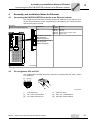
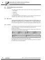
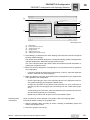
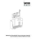
This chapter only describes the connection to Ethernet networks via X21 and X22. Connection and functionality via X37 (engineering) are described in the "UHX71B (Performance Class power)" manual.
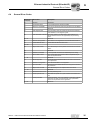
Front view
UHX71B with OSR71B (Ethernet)
Designation
LED
X21 X22
LED
Terminal
Function
LED 23.1
LED 23.2
LED 23.3
LED 23.4
Reserved
Reserved
Ethernet Communication status
System status
X21 X22
OnM -24+
X1
X21: Ethernet connection
LED Link (green)
LED Activity (yellow)
LAN3
X22: Ethernet connection
LED Link (green)
LED Activity (yellow)
L23.1
L23.4
L23.1
L23.4
LAN4 USB1 USB2 USB3
7995857803
4.2
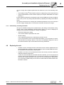
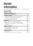
Pin assignment X21 and X22
Use prefabricated, shielded RJ45 plug connectors compliant with IEC 11801, edition
2.0, category 5.
[6]
[3] [2] [1]
12
3
6
A
B
6139704459
A
[1]
[3]
View from front
Pin 1 TX+ Transmit Plus
Pin 3 RX+ Receive Plus
Manual – UHX71B Controller with OSR71B Fieldbus Interface
B
[2]
[6]
View from back
Pin 2 TX– Transmit Minus
Pin 6 RX– Receive Minus
13
Assembly and Installation Notes for Ethernet
Shielding and routing bus cables
4
4.2.1
Connection controller / Ethernet
To connect the UHX71B-OSR71B controller to the Ethernet network, connect the Ethernet interface X21 or X22 (RJ45 plug connector) to the other network stations using a category 5, class D twisted-pair cable in accordance with IEC 11801 edition 2.0. The integrated switch assists you in implementing a line topology and provides auto-crossing
functions.
INFORMATION
•
•
4.3
According to IEC 802.3, the maximum cable length for 10/100 MBaud Ethernet
(10BaseT / 100BaseT), e.g. between 2 network stations, is 100 m.
We recommend that you do not directly connect non-SEW end devices to the
UHX71B-OSR71B controller in order to minimize the load on the end devices in
EtherNet/IP networks caused by undesired multicast data traffic. Connect nonSEW devices via a network component that supports the IGMP snooping functionality (e.g. managed switch).
Shielding and routing bus cables
Only use shielded cables and connection elements that meet the requirements of category 5, class D according to IEC 11801 edition 2.0.
Correct shielding of the bus cable attenuates electrical interference that can occur in industrial environments. The following measures ensure the best possible shielding:
•
Manually tighten the mounting screws on the connectors, modules, and equipotential
bonding conductors.
•
Use only connectors with a metal housing or a metalized housing.
•
Connect the shielding in the connector over a wide surface area.
•
Apply the shielding of the bus cable on both ends.
•
Route signal and bus cables in separate cable ducts. Do not route them parallel to
power cables (motor leads).
•
Use metallic, grounded cable racks in industrial environments.
•
Route the signal cable and the corresponding equipotential bonding close to each
other using the shortest possible route.
•
Avoid using plug connectors to extend bus cables.
•
Route the bus cables closely along existing grounding surfaces.
INFORMATION
In case of fluctuations in the ground potential, a compensating current may flow via the
bilaterally connected shield that is also connected to the protective earth (PE). Make
sure you supply adequate equipotential bonding in accordance with relevant VDE regulations in such a case.
14
Manual – UHX71B Controller with OSR71B Fieldbus Interface
Assembly and Installation Notes for Ethernet
The integrated Ethernet switch
4.4
4
The integrated Ethernet switch
You can use the integrated Ethernet switch to achieve line topologies known from the
fieldbus technology. Other bus topologies, such as star or tree, are also possible. Ring
topologies are not supported.
INFORMATION
The number of industrial Ethernet switches connected in line impacts the telegram
runtime. If a telegram passes through the units, the telegram runtime is delayed by the
store & forward function of the Ethernet switch:
•
•
For a telegram length of 64 bytes by approximately 10 µs (at 100 Mbit/s)
For a telegram length of 1500 bytes by approximately 130 µs (at 100 Mbit/s)
This means the more units a telegram has to pass through, the higher the telegram
runtime is.
4.4.1
Auto-crossing
The two ports leading out of the Ethernet switch have auto-crossing functionality. This
means that they can use both patch and cross-over cables to connect to the next Ethernet node.
4.4.2
Auto-negotiation
The baud rate and duplex mode are negotiated by both Ethernet nodes when establishing the connection. For this purpose, both Ethernet ports of the EtherNet/IP connection
support an auto-negotiation functionality and work with a baud rate of either 100 Mbit or
10 Mbit in full duplex or half-duplex mode.
4.4.3
4.5
Notes on multicast handling
•
The integrated Ethernet switch does not provide a filter function for Ethernet multicast telegrams. Multicast telegrams that are usually sent in Ethernet/IP networks
from the adapters (UHX71B-OSR71B controller) to the scanners (PLC) are passed
on to all switch ports.
•
IGMP Snooping (e.g. Managed Switches) is not supported.
•
SEW-EURODRIVE therefore recommends to connect the UHX71B-OSR71B controller in EtherNet/IP networks only with network components that support IGMP
snooping (e.g. managed switch) or that have safety mechanisms integrated against
excess multicast load (e.g. units from SEW-EURODRIVE). Units that do not have
this integrated function can fail due to high network loads.
Status LED
The LEDs of the UHX71B-OSR71B controller indicate the current status of the UFR41B
option and the fieldbus system. Depending on the set protocol, the LEDs have the following meaning.
4.5.1
Status LED in EtherNet/IP operation
LED L23.2
The LED L23.2 (NETWORK STATUS) indicates the state of the fieldbus system.
State of LED 23.2
Meaning
Off
The UHX-OSR71B controller does not yet have any IP parameters.
Manual – UHX71B Controller with OSR71B Fieldbus Interface
15
Assembly and Installation Notes for Ethernet
Status LED
4
LED L23.3
LED L23.4
4.5.2
State of LED 23.2
Meaning
Flashing green/red
The UHX-OSR71B performs a self test.
Flashing green
There is no controlling IO connection.
Green
There is a controlling EtherNet/IP connection.
Red
Conflict detected in the assigned IP addresses. Another station in the network
uses the same IP address.
Flashing red
The previously established controlling IO connection is in timeout state. The state
is reset by restarting communication.
LED L23.3 (MODULE STATUS) indicates that the bus electronics are operating correctly.
State of LED 23.3
Meaning
Off
The UHX71B-OSR71B controller is either not supplied with voltage or it is faulty.
Flashing green
Device has not been configured yet and is in "Standby" state.
Flashing green/red
The UHX71B-OSR71B controller performs a self test.
Green
The UHX71B-OSR71B controller is in normal operating state.
Red
The UHX71B-OSR71B controller is in error state.
Flashing red
Conflict detected in the assigned IP addresses. Another station in the network
uses the same IP address.
LED 23.4 (SYS) indicates the proper functioning of the fieldbus electronics (hardware).
State of LED 23.4
Diagnostics
Troubleshooting
Green
The fieldbus hardware is OK.
-
Orange
Hardware is being initialized.
-
Status LED in PROFINET operation
LED L23.2
The LED L23.2 (BUS FAULT) shows the status of the PROFINET.
State of LED L23.2
Cause of error
Troubleshooting
Off
PROFINET IO device is currently
exchanging data with the PROFINET
IO controller (Data Exchange).
-
Flashing red at 2 Hz
No data exchange.
-
Red
•
•
•
•
•
LED L23.3
16
Connection to the PROFINET IO
controller has failed.
PROFINET IO device does not
detect a link.
Bus interruption
PROFINET IO controller is not in
operation
•
•
Check the PROFINET connection
of the UHX71B-OSR71B controller
Check the PROFINET IO controller.
Check the cabling of your PROFINET network
LED L23.3 (SYS FAULT) indicates that the bus electronics are operating correctly.
State of LED L23.3
Cause of error
Off
No error
Red
Error in the UHX71B-OSR71B controller hardware.
Flashing red 2 Hz, for 3
s
DCP Signal Service is triggered via
fieldbus. The flashing function in the
PROFINET IO controller configuration is activated to visually localize
the stations.
Troubleshooting
Switch the unit on again. Consult SEW
Service if the error occurs again.
Manual – UHX71B Controller with OSR71B Fieldbus Interface
Assembly and Installation Notes for Ethernet
Status LED
LED L23.4
4.5.3
4
LED 23.4 (SYS) indicates the proper functioning of the fieldbus electronics (hardware).
State of LED 23.4
Diagnostics
Troubleshooting
Green
The fieldbus hardware is OK.
-
Orange
Hardware is being initialized.
-
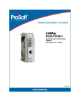
Link/Activity LED
LED "Activity"
X21
LED "Link"
X22
The two LEDs Link (green) and Activity (yellow) integrated in the RJ45 plug connectors (X21, X22) display the state of the Ethernet connection.
7869987467
LED/state
Meaning
Link/green
There is an Ethernet connection.
Link/off
There is no Ethernet connection.
Link/flashes
Locating function of SEW Address Editor (see chapter 4.8)
Activity/yellow
Data is currently being exchanged via Ethernet.
Manual – UHX71B Controller with OSR71B Fieldbus Interface
17
Assembly and Installation Notes for Ethernet
TCP/IP addressing and subnetworks
4
4.6
TCP/IP addressing and subnetworks
4.6.1
Introduction
The settings for the address of the IP protocol are made using the following parameters:
•
MAC address
•
IP address
•
Subnet mask
•
Standard gateway
The addressing mechanisms and subdivision of the IP networks into subnetworks are
explained in this chapter to help you set the parameters correctly.
4.6.2
MAC address
The MAC address (Media Access Controller) is the basis for all address settings. The
MAC address of an Ethernet device is a worldwide unique 6-byte value (48 bits). The
MAC address of SEW Ethernet devices is 00-0F-69-xx-xx-xx. The MAC address is difficult to handle for larger networks. This is why freely assignable IP addresses are used.
4.6.3
IP address
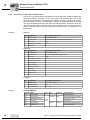
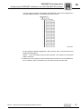
The IP address is a 32-bit value that uniquely identifies a node in the network. An IP address is represented by 4 decimal numbers separated by decimal points.
Example: 192.168.10.4
Each decimal number stands for one byte (= 8 bits) of the address and can also be represented using binary code (see following table).
Byte 1
11000000
Byte 2
.
Byte 3
10101000
.
00001010
Byte 4
.
00000100
The IP address comprises a network address and a node address (→ following table).
Network address
Node address
192.168.10
4
The part of the IP address that denotes the network and the part that identifies the node
is determined by the network class and the subnet mask.
Node addresses cannot consist of only zeros or ones (binary) because they represent
the network itself or a broadcast address.
18
Manual – UHX71B Controller with OSR71B Fieldbus Interface
Assembly and Installation Notes for Ethernet
TCP/IP addressing and subnetworks
4.6.4
4
Network classes
The first byte of the IP address determines the network class and as such represents
the division into network addresses and node addresses.
Value range
Byte 1
Network class
Complete network address
(Example)
Meaning
0 ... 127
A
101.22.3
10 = Network address
1.22.3 = Node address
128 ... 191
B
17216.52.4
172.16 = Network address
52.4 = Node address
192 ... 223
C
192.168.10.4
192.168.10 = Network address
4 = Node address
This rough division is not sufficient for a number of networks. They also use an explicit,
adjustable subnet mask.
4.6.5
Subnet mask
A subnet mask is used to divide the network classes into even finer sections. Like the
IP address, the subnet mask is represented by 4 decimal numbers separated by decimal
points.
Example: 255,255,255,128
Each decimal number stands for one byte (= 8 bits) of the subnet mask and can also be
represented using binary code (→ following table).
Byte 1
11111111
Byte 2
.
Byte 3
11111111
.
Byte 4
11111111
.
10000000
If you compare the IP addresses with the subnet masks, you see that in the binary representation of the subnet mask all ones determine the network address and all the zeros
determine the station address (see following table).
Byte 1
IP address
Subnet mask
decimal
192
Byte 2
.
168.
Byte 3
.
Byte 4
10
.
129
binary
11000000
.
10101000
.
00001010
.
10000001
decimal
255
.
255
.
255
.
128
binary
11111111
.
11111111
.
11111111
.
10000000
The class C network with the address 192.168.10. is further subdivided by the subnet
mask 255.255.255.128. 2 networks are created with the address 192.168.10.0 and
192.168.10.128.
The following node addresses are permitted in the two networks:
•
192.168.10.1 ... 192.168.10,126
•
192.168.10,129 ... 192.168.10,254
The network nodes use a logical AND operation for the IP address and the subnet mask
to determine whether there is a communication partner in the same network or in a different network. If the communication partner is in a different network, the standard gateway is addressed for passing on the data.
Manual – UHX71B Controller with OSR71B Fieldbus Interface
19
Assembly and Installation Notes for Ethernet
Setting the IP address parameters
4
4.6.6
Standard gateway
The standard gateway is also addressed via a 32-bit address. The 32-bit address is represented by 4 decimal numbers separated by decimal points.
Example: 192.168.10.1
The standard gateway establishes a connection to other networks. In this way, a network station that wants to address another station can use a logical AND operation with
the IP address and the subnet mask to determine whether the desired station is located
in the same network. If this is not the case, the node addresses the standard gateway
(router), which must be part of the actual network. The standard gateway then takes on
the job of transmitting the data packages.
If for the standard gateway, the same address is set as for the IP address, the standard
gateway is deactivated. The address of the standard gateway and the IP address must
be in the same subnetwork.
4.6.7
DHCP (Dynamic Host Configuration Protocol)
Instead of setting the 3 parameters IP address, subnet mask and standard gateway
manually, they can be assigned automatically by a DHCP server in the Ethernet network.
This means the IP address is assigned from a table, which contains the allocation of
MAC address to IP address.
Parameter P785 indicates whether the UHX71B-OSR71B controller expects the IP parameters to be assigned manually or via DHCP.
4.7
Setting the IP address parameters
4.7.1
Initial startup
The "DHCP" protocol (Dynamic Host Configuration Protocol) is activated as the default
setting for the UHX71B-OSR71B controller. This means that the option card expects its
IP address parameters from a DHCP server.
INFORMATION
There is a free DHCP server available on the Rockwell Automation homepage. The
tool is known as "BOOTP Utility" and can be downloaded from the following website:
http://www.ab.com/networks/bootp.html.
Once the DHCP server has been configured and the settings have been made for the
subnetwork screen and the standard gateway, the UHX71B-OSR71B controller must be
inserted in the assignment list of the DHCP server. The MAC ID of the UHX71BOSR71B controller is allocated a valid IP address.
INFORMATION
The configured IP address parameters are permanently adopted into the parameter
set if DHCP is deactivated after the IP address has been assigned.
4.7.2
Changing the IP address parameters after successful initial startup
If the UHX71B-OSR71B controller was started using a valid IP address, you can also
access the IP address parameters via the Ethernet interface.
20
Manual – UHX71B Controller with OSR71B Fieldbus Interface
Assembly and Installation Notes for Ethernet
Replacing the unit
4
You can change the IP address parameters via Ethernet by one of the following methods:
•
with the MOVITOOLS® MotionStudio software via [Diagnose] / [File System Monitor]
•
using the EtherNet/IP TCP/IP interface object (see chapter "EtherNet/IP CIP object
directory")
If the IP address parameters are assigned to the UHX71B-OSR71B controller via DHCP
server, then you can only change the parameters by adjusting the settings of the DHCP
server.
The options listed above for changing the IP address parameters only come into effect
once the supply voltages (DC 24 V) have been switched off and back on again.
4.7.3
Deactivating / activating the DHCP
The type of IP address assignment is determined by the setting of the attribute Configuration Control of the EtherNet/IP TCP/IP interface object. The value is displayed or
changed in the parameter P785 DHCP / Startup Configuration.
•
"Stored IP parameters" setting
The stored IP address parameters are used.
•
"DHCP" setting
The IP address parameters are requested by a DHCP server.
If you use the DHCP server from Rockwell Automation, you can activate or deactivate the DHCP by clicking a button. In this case, an EtherNet/IP telegram is sent to
the TCP/IP interface object of the station that is being addressed.
4.8
Replacing the unit
•
If DHCP is active, the assignment list of the DHCP server must be updated when the
UHX71B-OSR71B is replaced. The MAC address of the UHX71B-OSR71B controller is printed on its front panel for this purpose.
•
If DHCP is not active, the IP parameters saved on the memory card of the UHX71BOSR71B controller will be used.
If, after the UHX71B-OSR71B controller has been replaced, you do not plug the old
memory card into the replacement unit, you will have to perform a complete startup
with the new controller (if DHCP is not active incl. the IP parameters). Alternatively,
you can transfer a data backup to the new unit created with the MOVITOOLS® MotionStudio software.
Manual – UHX71B Controller with OSR71B Fieldbus Interface
21
Configuration and Startup (EtherNet/IP)
Validity of the EDS file for UHX71B-OSR71B
5
5
Configuration and Startup (EtherNet/IP)
This chapter provides information on the configuration of the EtherNet/IP master and
startup of the UHX71B-OSR71B controller for fieldbus operation. Prerequisite is the correct connection and setting of the IP address parameters of the UHX71B-OSR71B controller in accordance with the chapter "Assembly and Installation Instructions".
5.1
Validity of the EDS file for UHX71B-OSR71B
INFORMATION
Do not edit or amend the entries in the EDS file. SEW assumes no liability for inverter
malfunctions caused by a modified EDS file.
SEW-EURODRIVE provides the following EDS file for configuring the scanner (EtherNet/IP master):
•
SEW_CONTROLLER_POWER.eds
INFORMATION
Current versions of the EDS files for the UHX71B-OSR71B option are available on the
SEW homepage (http://www.sew-eurodrive.com) under the heading "Software".
5.2
Configuring the master (EtherNet/IP scanner)
The following example refers to configuration for the Allen-Bradley CompactLogix 1769L32E controller with RSLogix 5000 programming software. The EtherNet/IP interface is
already integrated into the CPU component of this controller.
INFORMATION
If a CPU without an EtherNet/IP interface is used, an Ethernet communication interface must first be added to the I/O configuration.
22
Manual – UHX71B Controller with OSR71B Fieldbus Interface
Configuration and Startup (EtherNet/IP)
Configuring the master (EtherNet/IP scanner)
5.2.1
5
Process data exchange
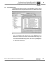
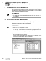
In the following project planning example, the UHX71B-OSR71B controller is added to
a project. To do so, go to the “Controller Organizer” screen in the RSLogix 5000 program
as shown in the screenshot below (use the tree structure on the left side of the screen).
7874677003
•
In the "IO Configuration" folder, select the entry "1769-L32E Ethernet Port LocalENB" as the Ethernet communication interface. Right-click and choose "New
Module" from the context menu. The selection window "Select Module" appears.
•
To add option UHX71B-OSR71B to the project, mark the entry “ETHERNET MODULE” in the “Communications” category. Confirm your selection by clicking [OK].
•
The "New Module" window opens.
Manual – UHX71B Controller with OSR71B Fieldbus Interface
23
5
Configuration and Startup (EtherNet/IP)
Configuring the master (EtherNet/IP scanner)
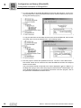
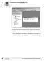
First enter the name under which the data is stored in the controller tags for the newly
created module, and then enter the IP address.
7874681483
24
•
In the “Comm Format” dropdown menu, choose “Data - INT” as the data format. Process data for UHX71B-OSR71B always contains 16 bits (INT).
•
In the "Connection Parameters" group box, enter the value "171" in the "Input Assembly Instance" input field. The input data of the PLC must be linked to the output
instance of UHX71B-OSR71B.
•
To establish a controlling connection, in the "Connection Parameters" group box
enter the value "161" in the "Output Assembly Instance" input field. The input data of
the PLC must be linked to the output instance of UHX71B-OSR71B.
•
In the selection fields "Input Size" and "Output Size", set a maximum value of "64"
(16 bit) as the data length.
•
In the "Configuration Size" selection field, enter the value "0". The "Configuration Assembly Instance" input field is not used in this case.
•
Click [OK] to complete the process.
•
To ensure compatibility with existing DeviceNet configurations, you can also choose
the data type "SINT" in the "Comm Format" selection field. In this case, you must ensure that an even number of bytes (2 – 128) is configured and that data consistency
is maintained during operation when the IO data is accessed.
Manual – UHX71B Controller with OSR71B Fieldbus Interface
Configuration and Startup (EtherNet/IP)
Settings in the UHX71B-OSR71B controller
5.2.2
5
Other settings
On the "Connection" tab page you can set the data rate and, if necessary, the error response of the controller.
8229832203
5.3
•
The UHX71B-OSR71B controller supports a minimum data rate (input field "Requested Packet Interval (RPI)") of 4 ms. Longer cycle times can be implemented
without any problems.
•
Click [OK]. You have now configured process data exchange with a UHX71BOSR71B.
Settings in the UHX71B-OSR71B controller
The creation of IEC programs is described in detail in the "MultiMotion for MOVI-PLC®"
manual. This is why only the fieldbus-specific characteristics are described in this chapter.
5.3.1
Process data configuration Ethernet/IP slave and modbus/TCP
To activate the fieldbus interface, set the Fieldbus selection parameter in the parameter
tree of MOVITOOLS® MotionStudio to the required bus type (Ethernet/IP or Modbus/TCP).
8229837195
Manual – UHX71B Controller with OSR71B Fieldbus Interface
25
Configuration and Startup (EtherNet/IP)
Settings in the UHX71B-OSR71B controller
5
In the "IP parameters" group box, enter the following addresses:
•
IP address
•
Subnet mask
•
Standard gateway
8229853963
INFORMATION
For Modbus/TCP, the timeout monitoring must take place in the application (e.g. via a
toggle bit).
5.3.2
Status of the Ethernet/IP fieldbus interface
The FbusGetInfoV2 function block makes the status and some display parameters of
the fieldbus interface available for the IEC program and for diagnostics.
FBusGetInfoV2
BOOL
Enable
Done
BOOL
Type
BOOL
ErrorID
BOOL
Address
UDINT
Baudrate
UDINT
Timeout
UDINT
BusType
T_PLC_BUS_TYPE
BusState
T_PLC_BUS_STATE
PdConfig
T_PLC_BUS_PD_CONFIG
7628791563
If there is no communication with the fieldbus master, the output Error is set to TRUE.
During an active fieldbus connection, the output Done is set to TRUE, and the outputs
Address, Baud rate, timeout and Bus type show the respective parameters as they were
set via the parameter tree in MOVITOOLS® MotionStudio or via PLC.
26
Manual – UHX71B Controller with OSR71B Fieldbus Interface
Configuration and Startup (EtherNet/IP)
Configuration examples in RSLogix5000
5.3.3
5
Checking the process data communication
Now actual values can be read from the UHX71B-OSR71B controller and setpoint values can be written. The process data should correspond with the values displayed in the
PLC Editor or in the diagnostics plug-in of the active IEC program in MOVITOOLS® MotionStudio.
INFORMATION
For more detailed information on process data communication in the IEC program,
refer to the publication "MultiMotion for MOVI-PLC®".
5.4
Configuration examples in RSLogix5000
5.4.1
UHX71B-OSR71B with 16 PD data exchange
1. Set the IP address of the UHX71B-OSR71B controller (see chapter Setting the IP address parameters).
2. Add the UHX71B-OSR71B to the Ehernet/IP configuration according to chapter
"Configuration of the master (Ethernet/IP scanner)".
3. You can now start integration into the RSLogix project.
To do so, create a controller tag with a user-defined data type to create a simple, data
consistent interface to the process data of the UHX71B-OSR71B controller (see following figure).
7882429323
The description for the process input and output data of the controller tag can match
the definition of the process data (PD) in the UHX71B-OSR71B.
Manual – UHX71B Controller with OSR71B Fieldbus Interface
27
5
Configuration and Startup (EtherNet/IP)
Configuration examples in RSLogix5000
4. To copy the data of the UHX71B-OSR71B to the new data structure, a CPS command is added at the start of the MainRoutine which reads the data from the controller tag (see following figure).
7882586123
To copy the data from the new data structure to the UHX71B-OSR71B, insert a CPS
command at the end of the "MainRoutine" (see following figure).
7882591115
5. Now the project is saved and uploaded to the PLC. The PLC is set to RUN mode.
Now actual values can be read from the UHX71B-OSR71B controller and setpoint
values can be written.
The process data should correspond to the values displayed in the PLC Editor or in
the diagnostics plug-in of the active IEC program in MOVITOOLS® MotionStudio. For
more detailed information on process data connection in the IEC program, refer to
the publication "MultiMotion for MOVI-PLC®".
28
Manual – UHX71B Controller with OSR71B Fieldbus Interface
Ethernet Industrial Protocol (EtherNet/IP)
Introduction
6
Ethernet Industrial Protocol (EtherNet/IP)
6.1
Introduction
I
6
0
The EtherNet Industrial Protocol (EtherNet/IP) is an open communication standard
based on the classic EtherNet protocols TCP/IP and UDP/IP.
EtherNet/IP was defined by the Open DeviceNet Vendor Association (ODVA) and ControlNet International (CI).
With EtherNet/IP, Ethernet technology is expanded to include the CIP (Common Industrial Protocol) application protocol. CIP is known in the field of automation engineering
because it is also used for DeviceNet and ControlNet as an application protocol.
6.2
Process data exchange
Up to 120 process data words can be exchanged with an EtherNet/IP master (scanner)
depending on the use of the UHX71B-OSR71B unit. The EtherNet/IP master (scanner)
sets the process data length when opening the connection.
In addition to a controlling "Exclusive Owner Connection", up to two additional "Listen
Only Connections" are available. This means the actual values of the drive can also be
read out by stand-by controllers or visualization devices.
If there is already a controlling connection via Modbus/TCP, you cannot activate an "Exclusive Owner Connection" via EtherNet/IP before a power-on reset.
6.2.1
Timeout response
The timeout status is triggered by the UHX71B-OSR71B option. The timeout interval
must be set by the EtherNet/IP master (scanner) when the connection is established.
The EtherNet/IP specification refers to a "Requested Packet Interval (RPI)" rather than
a timeout time in this case.
The timeout interval displayed in the MOVITOOLS® MotionStudio parameter tree results from the Requested Packet Interval (RPI) multiplied with the "Timeout Multiplier".
This timeout interval is retained in the device when an "Exclusive Owner Connection" is
removed, and the device switches to timeout status after the timeout interval has
elapsed. The timeout status is displayed on the front of the UHX71B-OSR71B by the
flashing red L13 LED.
A you can only activate the timeout delay via the bus, you must not change the value via
MOVITOOLS® MotionStudio.
The timeout state causes the response programmed in the IEC program.
The timeout status can be reset via EtherNet/IP as follows:
•
Via the reset service of the identity object (class 0x01, instance 0x01, undetermined
attribute)
•
By re-establishing the connection
•
Via the reset bit in the control word
Manual – UHX71B Controller with OSR71B Fieldbus Interface
29
I
6
0
6.3
Ethernet Industrial Protocol (EtherNet/IP)
CIP object directory
CIP object directory
In the Common Industrial Protocol, all unit data can be accessed via objects. The objects listed in the following table are integrated in the UHX71B-OSR71B.
Class [hex]
Name
01
Identity object
02
Message Router Object
04
Assembly Object
06
Connection Manager Object
07
Register Object
0F
Parameter Object
64
Vardata Object
F5
TCP/IP Interface Object
F6
EtherNet Link Object
The meaning of the objects and a description of how to access them is given in the following section.
6.3.1
Identity object
•
The identity object contains general information on the EtherNet/IP device.
•
Class code: 01hex
Class
Attribute
Access
Name
Data type
Default value [hex]
Description
1
Get
Revision
UINT
0001
Revision 1
2
Get
Max Instance
UINT
0001
Maximum instance
Attribute
Access
Name
Data type
Default value [hex]
Description
1
Get
Vendor
ID
UINT
013B
SEW-EURODRIVE GmbH & Co
KG
2
Get
Device
Type
UINT
0065
Manufacturer-specific type
3
Get
Product
Code
UINT
000A
Product no.10: UHX71B
Revision
STRUCT
of
Major
Revision
USINT
Minor
Revision
USINT
Instance 1
4
Revision of the identity object,
depends on firmware version
5
Get
Status
WORD
→ Table in "Coding of attribute 5
Status"
6
Get
Serial
number
UDINT
Unique serial number of fieldbus
connection
7
Get
Product
Name
SHORT_
STRING
•
30
Get
SEW CONTROLLER
POWER
Product name
Coding of attribute 5 "Status"
Bit
Name
Description
0
Owned
Controlling connection is active
1
-
Reserved
Manual – UHX71B Controller with OSR71B Fieldbus Interface
Ethernet Industrial Protocol (EtherNet/IP)
CIP object directory
Bit
Name
Description
2
Configured
Configuration complete
3
-
Reserved
4–7
Extended Device Status
See table "Coding of the Extended Device Status"
8
Minor Recoverable Fault
Minor error that can be remedied
9
Minor Unrecoverable Fault
Minor error that cannot be remedied
10
Major Recoverable Fault
Major error that can be remedied
11
Major Unrecoverable Fault
Major error that cannot be remedied
12 – 15
-
Reserved
•
Supported services
6.3.2
I
6
0
Coding of the “Extended device status” (bits 4 – 7):
Value [binary]
Description
0000
Unknown
0010
At least one faulty I/O connection
0011
No I/O connection established
0110
At least one I/O connection active
Service code [hex]
Service Name
Class
Instance
01
Get_Attributes_All
X
X
05
Reset
-
X
0E
Get_Attribute_Single
X
X
Message router object
•
The message router object provides information on the implemented objects.
•
Class code: 02hex
Class
Attribute
Access
Name
Data type
Default value [hex]
Description
1
Get
Revision
UINT
0001
Revision 1
Attribute
Access
Name
Data type
Default value [hex]
Description
1
Get
Object_List
STRUCT of
Object list comprising:
• Number of objects
• List of objects
Instance 1
2
Get
Number
UINT
0009
Classes
ARRAY of
UINT
01 00 02 00
04 00 06 00
07 00 0F 00
64 00 F5 00
F6 00
Number
Available
UINT
0009
Manual – UHX71B Controller with OSR71B Fieldbus Interface
Maximum number of connections
31
I
6
0
Ethernet Industrial Protocol (EtherNet/IP)
CIP object directory
Supported services
6.3.3
Service code [hex]
Service Name
Class
Instance
01
Get_Attributes_All
X
-
0E
Get_Attribute_Single
X
X
Assembly object
•
The assembly object is used to access the UHX71B-OSR71B process data. IO connections can be created for the instances of the assembly object to exchange cyclic
process data.
•
Class code: 04hex
Class
Instance 161 –
SEW PO data
range
Instance 121 –
"Heartbeat"
Instance 171 –
SEW PI data section
Attribute
Access
Name
Data type
Default value [hex]
Description
1
2
Get
Revision
UINT
0002
Revision 2
Get
Max Instance
UINT
0082
Maximum instance
This instance is used to access the UHX71B-OSR71B process output data.
MOVIDRIVE® can be controlled by only one scanner. Therefore, only one connection
can be established with this instance.
Attribute
Access
Name
Data type
Default value [hex]
Description
3
Get
Data
Array of
BYTE
-
OUTPUT assembly
This instance is accessed when the scanner wants to establish an input only connection.
No process output data is sent with this type of connection. It is used only to read process input data.
Attribute
Access
Name
Data type
Default value [hex]
Description
3
Get
Data
Array of
BYTE
-
OUTPUT assembly
Data size = 0
This instance is used to access the UHX71B-OSR71B process input data. Several multicast connections or a point-to-point connection can be established to this instance.
Attribute
Access
Name
Data type
Default value [hex]
Description
3
Get
Data
Array of
BYTE
-
INPUT assembly
INFORMATION
The designations "INPUT assembly" and "OUTPUT assembly" refer to the processes
as seen from the network's point of view. An "INPUT assembly"” produces data on the
network, "OUTPUT assembly" consumes data from the network.
Supported services
32
Service code [hex]
Service Name
Class
Instance 161
Instance 121
Instance 171
0E
Get_Attribute_Single
X
X
-
X
Manual – UHX71B Controller with OSR71B Fieldbus Interface
Ethernet Industrial Protocol (EtherNet/IP)
CIP object directory
6.3.4
I
6
0
TCP/IP interface object
•
The TCP/IP interface object enables the IP parameters to be configured via EtherNet/IP.
•
Class code: F5hex
Class
Attribute
Access
Name
Data type
Default value [hex]
Description
1
Get
Revision
UINT
0001
Revision 1
2
Get
Max Instance
UINT
0001
Maximum instance
3
Get
Number of
Instances
UINT
0001
DHR41B has one TCP/IP
interface
Attribute
Access
Name
Data type
Default value [hex]
Description
1
Get
Status
DWORD
00000001
Valid configuration
2
Get
Configuration
capability
DWORD
00000014
The interface configuration attribute (5) is writable.
The DHCP can be used for
configuration.
3
Set
Configuration
control
DWORD
00000002
0 = The unit uses the
stored IP parameters at
startup.
2 = The unit waits for its IP
configuration via DHCP at
startup.
4
Get
Physical Link
Object
STRUCT of
Path Size
UINT
0002
Path
Padded
EPATH
20 F6 24 01
Interface configuration
STRUCT of
IP Address
UDINT
Current IP address
Network Mask
UDINT
Current subnetwork mask
Gateway
Address
UDINT
Currently set standard
gateway
Instance 1
5
Set
6
Supported services
6.3.5
Get
Reference to the EtherNet
link object (class code
0xF6) as sublayer.
Name Server
UDINT
00000000
DNS is not supported
Name Server 2
UDINT
00000000
DNS is not supported
Domain Name
STRING
sew.de
Host Name
STRING
Not used
Service code [hex]
Service Name
Class
Instance
01
Get_Attributes_All
X
_
0E
Get_Attribute_Single
X
X
10
Set_Attribute_Single
-
X
Ethernet link object
•
Information on the Ethernet communication interface is stored in the Ethernet link object.
•
Class code: F6hex
Manual – UHX71B Controller with OSR71B Fieldbus Interface
33
I
6
0
Ethernet Industrial Protocol (EtherNet/IP)
CIP object directory
Class
Instance 1 – Ethernet connection X21
Attribute
Acces
s
Name
Data type
Default
value [hex]
Description
1
Get
Revision
UINT
0002
Revision 2
2
Get
Max Instance
UINT
0002
Maximum instance
3
Get
Number of
Instances
UINT
0002
DHR41B has 2 Ethernet interfaces
Attribute
Acces
s
Name
Data type
Default value
[hex]
Description
1
Get
Interface
Speed
UDINT
00000064
Default value = 100 → transmission
speed in MBit/s
2
Get
Interface
Flags
DWORD
•
•
•
•
•
Instance 2 – Ethernet connection X22
3
Get
Physical
Address
ARRAY of
6 USINTs
00 0F 69 xx xx xx
MAC ID
SEW MAC OUI: 00 0F 69
Attribute
Acces
s
Name
Data type
Default value [hex]
Description
1
Get
Interface
Speed
UDINT
00000064
Default value = 100 → transmission
speed in MBit/s
2
Get
Interface
Flags
DWORD
•
•
•
•
•
3
Supported services
34
Bit 0 displays the active link
Bit 1 displays full duplex mode
Bit 2 – bit 4 indicate the negotiation status
Bit 5 shows whether the manual
setting has to be reset
Bit 6 indicates a local hardware
error
Get
Physical
Address
ARRAY of
6 USINTs
00 0F 69 xx xx xx xx
Bit 0 displays the active link
Bit 1 displays full duplex mode
Bit 2 – bit 4 indicate the negotiation status
Bit 5 shows whether the manual
setting has to be reset
Bit 6 indicates a local hardware
error
MAC ID
SEW MAC OUI: 00 0F 69
Service code [hex]
Service Name
Class
Instance
01
Get_Attributes_All
X
_
0E
Get_Attribute_Single
X
X
Manual – UHX71B Controller with OSR71B Fieldbus Interface
Ethernet Industrial Protocol (EtherNet/IP)
General Error Codes
6.4
I
6
0
General Error Codes
General error
code (hex)
Error name
Description
00
Success
Successful
01
Connection failure
A connection-specific service has failed.
02
Resource unavailable
The source required for performing the service is unavailable.
04
Path segment error
The processing node was unable to interpret the "Path Segment Identifier" or the segment syntax.
05
Path destination unknown
The "Path" refers to an object class, object instance or a
structural element that is not supported by the processing
node.
03
Reserved
06 – 07
Reserved
08
Service not supported
The service is not supported for the selected class/instance
09
Invalid attribute value
Invalid attribute data have been sent.
Object state conflict
The selected object cannot perform the service in its current
status.
0E
Attribute not settable
It is not possible to access the selected object for writing.
10
Device state conflict
The current status of the device makes it impossible to perform the required service.
13
Not enough data
The length of the transferred data is too short for the service
to be performed.
14
Attribute not supported
The selected attribute is not supported.
15
Too much data
The length of the transferred data is too long for the service to
be performed.
16
Object does not exist
The selected object is not implemented in the device.
1E
Embedded Service Error
Internal processing error
1F
Vendor specific error
Manufacturer-specific error (see "Fieldbus Unit Profile" manual)
20
Invalid parameter
Invalid parameter. This error message is used when a parameter does not satisfy the requirements of the specification
and/or the requirements of the application.
0A – 0B
0C
0D
Reserved
11 – 12
Reserved
17 – 1D
Reserved
21 – FF
Manual – UHX71B Controller with OSR71B Fieldbus Interface
Reserved
35
I
7
0
7
Configuration and Startup (Modbus/TCP)
Configuration for the master (Modbus scanner)
Configuration and Startup (Modbus/TCP)
This section provides information about the configuration of the Modbus/TCP master
and startup of the inverter for fieldbus operation. Prerequisite is the correct connection
and setting of the IP address parameters of the UHX71B-OSR71 in accordance with the
section "Assembly and Installation Instructions".
INFORMATION
•
•
7.1
There are no specific unit description files for Modbus/TCP.
For Modbus/TCP, the timeout monitoring must take place in the application (e.g.
via a toggle bit).
Configuration for the master (Modbus scanner)
The first example refers to the configuration and programming of a Schneider Electric
control system TSX Premium P57203 using the programming software PL7 PRO. An
ETY4103 is used as the Ethernet component. The information and illustrations are
based on the English version of the PL7 PRO software.
INFORMATION
•
•
7.1.1
Enter values in PL7 PRO using the keypad.
As Ethernet bus master, use components from Schneider Electric that support I/O
scanning. The Modbus/TCP interface module for SEW drives cannot be addressed
via "Peer Cop". However, Ethernet-Busmasters that only support "Peer Cop" can
access the drives from the PLC program using read and write commands.
Hardware configuration
•
Start PL7 PRO and enter the control type.
•
Enter the hardware configuration for the control system in the application browser
under STATION / Configuration / Hardware configuration.
7898326155
36
Manual – UHX71B Controller with OSR71B Fieldbus Interface
Configuration and Startup (Modbus/TCP)
Configuration for the master (Modbus scanner)
7.1.2
7
Settings for the Ethernet component
•
To open the configuration window, double-click on the Ethernet component.
•
If you have a non-extendable rack, enter a "1" in the "Network" input field in the
"XWAY address" section.
•
Enter the number of the slot that the Ethernet component is plugged into (here: 2) in
the input field "Station" in the "XWAY address" section. 2). In this case, the XWAY
address is 1.2.
•
In the section "IP address configuration", select the checkbox "Configured". Enter the
IP address and the network parameters in the input fields "IP address", "Subnetwork
mask" and "Gateway address". If the control system is to receive the address parameters via a DHCP server, select the radio button "Client/Server configuration" in the
section "IP address configuration".
•
In the "Ethernet configuration" section, select the checkbox "Ethernet II".
•
In the "Module utilities" group, select the "IO Scanning" radio button.
7898818699
Manual – UHX71B Controller with OSR71B Fieldbus Interface
37
Configuration and Startup (Modbus/TCP)
Configuration for the master (Modbus scanner)
7
7.1.3
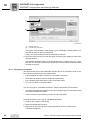
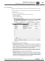
Addressing the drive using I/O scanning
•
Select the "IO Scanning" tab. In this tab page you specify which of the stations connected to the Modbus are to exchange cyclical data.
•
In the section "Master %MW zones" enter the control memory areas that are to be
used to exchange cyclical data with the Modbus stations. You will use the memory
addresses later in your PLC program.
•
Enter the following in the "Scanned peripherals" group:
– In the "IP address" input field, enter the IP address of the SEW drive.
– In the "Unit ID" field, enter "0".
– In the "Repetitive rate" dropdown menu, enter the cycle time that is used to address the stations.
– Enter the value "4 "in the input fields "RD ref.slave" and "WR ref. slave" as the
cyclical data are available from offset 4.
– In the input fields "RD count" and "WR count" enter the number of words to be
exchanged. The values must be the same in both fields. You can set 1 – 64 words
for the UHX71B-OSR71B.
7900597387
38
•
Click on the button "Confirm" to confirm the rack configuration and the global configuration.
•
Once you have transferred your settings and started the program, the color of LED
L13 (NETWORK/STATUS) of DHR41B changes to green (see chapter "Status
LED").
Manual – UHX71B Controller with OSR71B Fieldbus Interface
Configuration and Startup (Modbus/TCP)
Settings in the UHX71B-OSR71B controller
7.2
7
Settings in the UHX71B-OSR71B controller
The creation of IEC programs is described in detail in the "MOVI-PLC®" manual. This
section only describes the fieldbus-specific characteristics.
7.2.1
Process data configuration
The process data interface is normally configured by the master (scanner). The master
sets the number of process data words.
In the parameter tree of MOVITOOLS® MotionStudio (index 8451), the currently set
value is displayed in the field "PD configuration" (see following figure).
7946698251
INFORMATION
For Modbus/TCP, the timeout monitoring must take place in the application (e.g. via a
toggle bit).
7.3
Project planning example in PL7 PRO
7.3.1
UHX71B-OSR71B controller with 16 PD data exchange
1. Set the IP address of the UHX71B-OSR7141B controller (see chapter Setting the IP
address parameters).
2. Integrate the UHX71B-OSR71B into the configuration for the IO scanning according
to section "Configuration of the master (Modbus scanner)".
3. Now, the integration into the PLC project can be performed.
4. Create a new section in PL7 PRO in the application browser under [Station] /
[Program] / [Mast Task] / [Sections] .
Manual – UHX71B Controller with OSR71B Fieldbus Interface
39
7
Configuration and Startup (Modbus/TCP)
Project planning example in PL7 PRO
5. In this example, the setpoints for the drive start from MW150 (see following figure).
7956122507
6. Now the project is saved and uploaded to the PLC. The PLC is set to RUN mode.
Now actual values can be read from the UHX71B-OSR71B controller and setpoint
values can be written.
The process data should correspond to the values displayed in the PLC Editor or in
the diagnostics plug-in of the active IEC program in MOVITOOLS® MotionStudio. For
more detailed information on the process connection in the IEC program, refer to the
publication "MultiMotion for MOVI-PLC®".
40
Manual – UHX71B Controller with OSR71B Fieldbus Interface
Configuration and Startup (Modbus/TCP)
Examples for data exchange via Modbus/TCP
7.4
7
Examples for data exchange via Modbus/TCP
As there are many different master systems and software solutions available for Modbus/TCP for standard PCs, there is no "reference controller" the examples are based on.
This is why this section gives detailed examples regarding the telegram structure.
You can use the telegram structure from these examples and compare it to the structure
used in your application for troubleshooting purposes. There are simple tools for recording telegrams via the Ethernet network, e.g. Wireshark (see following figure), Packetizer
etc. These freeware tools are available on the Internet.
Observe that tracing all Ethernet telegrams in a network is only possible with a tab, hub
or a switch with a port mirror function. The telegrams sent from and to the PC which is
also used for recording can always be recorded, of course.
7956560139
The figure above provides an example of how setpoints are written (FC16) to the Modbus/TCP slave with IP address 10.3.71.119. The 3 process data words are located from
offset 4 (reference number) and are addressed via unit ID 255.
All the other examples merely describe the Modbus/TCP part of the telegram. The
TCP/IP part of the telegram, as well as establishing and dropping a TCP/IP connection
are not explained in detail.
Manual – UHX71B Controller with OSR71B Fieldbus Interface
41
Configuration and Startup (Modbus/TCP)
Examples for data exchange via Modbus/TCP
7
7.4.1
Writing and reading process data
The process data exchange can be performed either via FC3 (read) and FC16 (write),
or FC23 (read and write):
For writing 3 process data words (setpoints) to a Modbus/TCP slave via FC16, the
TCP/IP telegram to port 502 is structured as illustrated above.
Byte
0
1
2
3
Value
Meaning
0x00
Transaction identifier
0x00
Protocol identifier
4
0x00
5
0x0d
6
7
8
0x00
9
0x04
Interpretation
Length field
Number of bytes after byte 5:
3 (number PD) × 2 + 7 = 13
0xFF
Unit identifier
Must be 0 or 255
ox10
Function code
Service = FC16 (Write Register)
Write Reference-number
Offset where PD start:
Must always be 4
Write word count
Number of PD (here 3):
Must for PD 1...64
Write byte count
Number of PD × 2 = 6
10
0x00
11
0x03
12
0x06
13
0x00
14
0x11
15
0x22
16
0x33
17
0x44
18
0x55
Help
For a detailed description
refer to the Modbus/TCP
specification and section
"Modbus protocol (Modbus/TCP)"
Process output data word 1
Data
Process output data word 2
Data mapping and definition,
see IEC program
Process output data word 3
Only bytes 0-11 are returned in the response telegram of port 502 of the Modbus/TCP
slave, where all values remain unchanged with the exception of byte 5. Byte 5 (low byte
length field) is corrected to value 6.
42
Manual – UHX71B Controller with OSR71B Fieldbus Interface
Configuration and Startup (Modbus/TCP)
Examples for data exchange via Modbus/TCP
7
During process data exchange via FC23, the telegram that is used to write and read 3
process data words (PD) each is structured as follows.
Byte
0
1
2
3
Valu
e
Meaning
0x00
Transaction identifier
0x00
Protocol identifier
4
0x00
5
0x11
6
Interpretation
Length field
Number of bytes after byte 5:
3 (number PD) × 2 + 11 = 17
0xFF
Unit identifier
Must be 0 or 255
7
0x10
Function code
Service = FC23 (read + write register)
8
0x00
9
0x04
Read reference number
Offset where PD start:
Must always be 4
Read word count
Number of PD (here 3):
Must for PD 1 – 64
Write reference number
Offset where PD start:
Must always be 4
Write word count
Number of PD (here 3):
see read word count
Write byte count
Number of PD × 2 = 6
10
0x00
11
0x03
12
0x00
13
0x04
14
0x00
15
0x03
16
0x06
17
0x00
18
0x11
19
0x22
20
0x33
21
0x44
22
0x55
Help
For a detailed description
refer to the Modbus/TCP
specification and section
"Modbus protocol (Modbus/TCP)"
Process output data word 1
Data
Process output data word 2
Data mapping and definition,
see IEC program
Process output data word 3
The following data bytes are returned in the response telegram of the Modbus/TCP
slave.
Byte
0
1
2
3
Valu
e
Meaning
0x00
Transaction identifier
0x00
Protocol identifier
4
0x00
5
0x09
6
Interpretation
Length field
Number of bytes after byte 5:
3 (number PD) × 2 + +3 = 9
0xFF
Unit identifier
Must be 0 or 255
7
0x17
Function code
Service = FC23 (read + write register)
8
0x06
Write byte count
Number of PD × 2 = 6
9
0x00
10
0xAA
11
0xBB
12
0xCC
13
0xDD
14
0xEE
Help
For a detailed description
refer to the Modbus/TCP
specification and section
"Modbus protocol (Modbus/TCP)"
Process input data word 1
Data
Manual – UHX71B Controller with OSR71B Fieldbus Interface
Process input data word 2
Data mapping and definition, see IEC program
Process input data word 3
43
Modbus Protocol (Modbus/TCP)
Introduction
8
8
Modbus Protocol (Modbus/TCP)
8.1
Introduction
Modbus/TCP is an open protocol based on TCP/IP. It was one of the first protocol types
to become standard in industrial Ethernet interfaces for process data transfer.
Modbus frames are exchanged via the TCP/IP port 502. Every master IP address is accepted. Modbus exclusively uses the coding "BIG ENDIAN" (Motorola data format or
high byte first).
Access via "Peer Cop" is not possible. Make sure that the bus master supports "IO scanning".
Modbus/TCP is integrated into the UHX71B-OSR71B as of firmware version .11.
8.1.1
Mapping and addressing
The logic Modbus address range is 64 k words and is addressed via the reference number (offset). Four different tables can be in the address range:
•
Binary inputs (RO)
•
Binary outputs (RW)
•
Input register (RO)
•
Output register (RW)
The tables can be separated or overlapping.
The UHX71B-OSR71B option provides the following data areas:
•
For process data transfer, there is a table that allows for write access (for setpoint
values) as well as read access (for actual values).
This table starts at offset 4 and ends at offset 0FFhex. It contains the 1 – 64 cyclically
transferred process data words.
•
The process data output words from the controller are also saved in another table. It
allows for one or several additional clients (e.g. visualization) to read the current setpoint values.
This table starts at offset 104hex and ends at offset 1FFhex.
•
The remaining address scope from offset 400hex to FFFFhex is reserved and must
not be addressed.
The data word at offset 219hex (8606dec) is a special case, it allows for writing (and
reading) the timeout monitoring time.
INFORMATION
Note the following for control systems from Schneider Electric:
The address range often starts with 40001hex, which corresponds to an offset with the
value "0".
44
Manual – UHX71B Controller with OSR71B Fieldbus Interface
Modbus Protocol (Modbus/TCP)
Protocol structure
8.1.2
I
8
0
Services (function codes)
For process data exchange, parameter data exchange and unit identification, the
UHX71B-OSR71B provides 4 FC.. services (Function Codes).
•
FC 3 Read Holding Registers
•
FC16 Write Multiple Registers
•
FC23 Read/Write Multiple Registers
•
FC43 Read Device Identification
The FC3 and FC16 services allow reading or writing of one or more registers. FC23 allows a register block to be read and written simultaneously. FC43 can be used for a unit
identification by reading out the identity parameters.
8.1.3
Access
The implemented registers and possible services (function codes) for data exchange
are summarized in the following table.
Meaning of
8.2
Offset (hex)
Read
Write
Access
Comment
0–3
-
-
-
Reserved
4 – FF
Process input
data (actual values)
Process output data
(setpoint values)
FC3,
FC16,
FC23
0 – 64 words
100 – 103
-
-
-
Reserved
104 – 1FF
Process output
data (setpoint values)
-
FC3
For reading the setpoint values by
a client other than the controlling
one
200 – 2FF
Result acyclical
parameter channel
Request acyclical
parameter channel
FC3,
FC16,
FC23
4 words
300 – FFFF
-
-
-
Reserved
Special
case: 219E
(8606dec)
Fieldbus timeout
interval, read
value
Fieldbus timeout
interval, write value
FC3, FC16
Parameter P819: 16-bit value, timeout interval in ms
Protocol structure
The Modbus protocol consists of a header and function code data. The header is the
same for all request/response telegrams and error messages (exceptions). Depending
on the function code, a different number of data is attached to the header (see following
picture).
MBAP Header
Transaction-ID
Protocol-ID
Length (1+1+N)
Function Code-Data
UI-D
FC
N Data
7971408907
Manual – UHX71B Controller with OSR71B Fieldbus Interface
45
I
8
0
8.2.1
Modbus Protocol (Modbus/TCP)
Protocol structure
Header
The protocol bytes of the header are described in the following table:
Byte
Designation
Meaning
Transaction identifier
Often "0", is simply copied by the server (slave)
Protocol identifier
0
4
Length field (upper byte)
0
5
Length field (lower byte)
Number of function codes data bytes +1 (Unit identifier)
6
Unit identifier (slave address)
This is the slave address. In order to access the UHX71BOSR71B process data, it must be set to "0" (0x00) or 255 (0xFF).
The following address assignments apply to the parameter channel access (Offset 200 - 203hex):
• 0 or 254 for parameters of the UHX71B-OSR71B
• 1 - 253 for parameters of a lower-level unit connected to
UHX71B-OSR71B. The assignment of unit identifier to the
units on the system buses is determined via the routing table
on the UHX71B-OSR71B memory card (see chapter Appendix).
7
Function code
Requested service
8 ...
Data
Data depending on requested service
0
1
2
3
46
•
The slave simply copies the transaction identifier (byte 0 and 1). It can help the master to identify related actions.
•
The Protocol identifier (byte 2 and 3) must always be "0".
•
The length bytes (byte 4 and 5) specify the number of bytes occurring in the length
field. As the maximum telegram length is 255 bytes, the "upper byte" must be "0".
•
The unit identifier (byte 6) can be used for distinguishing between several connected
stations (e.g. bridges or gateways). It has the function of a subaddress that is only
used for parameter access in SEW units. The process data are always mapped to
the unit that is addressed via the unit identifier 0 or FFhex.
•
The 7 bytes of the header are followed by the function code and the data.
Manual – UHX71B Controller with OSR71B Fieldbus Interface
Modbus Protocol (Modbus/TCP)
Protocol structure
8.2.2
I
8
0
Service FC3 – Read Holding Registers
With the service FC3 Read holding registers, you can read a variable number of registers (see following figure).
MBAP Header
T- ID (0x00)
Prot-ID (0x00)
Function Code-Data(FC03)
Length (1+5)
UI-D
FC
(0x03)
Read Address
Read WordCount
7971446283
Example
Request:
Byte
Designation
Meaning/permitted values
0–6
MBAP header
See section "Header"
7
Function code
Requested service: 3 (Read Holding Register)
8
Reference number (high)
Offset
9
Reference number (low)
Offset
10
Word count (high)
Number of words (register)
11
Word count (low)
Number of words (register)
Response:
Byte
Designation
Meaning/permitted values
0–6
MBAP header
See section "Header"
7
Function code
Service: 3 (Read Holding Register)
8
Byte count
Number of following bytes
9....
Data
2 – ... Data bytes depending on length
Exception:
Byte
Designation
Meaning/permitted values
0–6
MBAP header
See section "Header"
7
Function code
83hex
8
Exception Code
Error code
Manual – UHX71B Controller with OSR71B Fieldbus Interface
47
I
8
0
8.2.3
Modbus Protocol (Modbus/TCP)
Protocol structure
FC16 – Write Multiple Registers
With the service FC16 Write Multiple Registers you can write a variable number of registers (see following figure).
MBAP Header
T- ID (0x00)
Prot-ID (0x00)
Length
(1+6+N)
Function Code-Data(FC16)
UI-D
(0x00)
Bytes
FC
Write Address Write WordCount (N)
(0x10)
Write Data
(1 ... N)
7971450763
Example
Request:
Byte
Designation
Meaning/permitted values
0–6
MBAP header
See section "Header"
7
Function code
Requested service: 16 (Write Multiple Registers)
8
Reference number (high)
Offset
9
Reference number (low)
Offset
10
Word count (high)
Number of words (register)
11
Word count (low)
Number of words (register)
12
Byte count
2* Word Count
13 ...
Register values
2 – ... Data bytes depending on length
Response:
Byte
Designation
Meaning/permitted values
0–6
MBAP header
See section "Header"
7
Function code
Service: 16 (Write Multiple Registers)
8
Reference number (high)
Offset
9
Reference number (low)
Offset
10
Word count (high)
Number of words (register)
11
Word count (low)
Number of words (register)
Exception:
48
Byte
Designation
Meaning/permitted values
0–6
MBAP header
See section "Header"
7
Function code
90hex
8
Exception Code
Error code
Manual – UHX71B Controller with OSR71B Fieldbus Interface
I
Modbus Protocol (Modbus/TCP)
Protocol structure
8.2.4
8
0
Service FC23 – Read/Write Multiple Registers
With the service FC23 Read/write multiple registers, you can simultaneously write and
read a variable number of registers. The write access is carried out first. Preferably, this
service is used for the process data (see following picture).
MBAP Header
T- ID (0x00) Prot-ID (0x00)
Length
(1+10+N)
Function Code-Data (FC23)
UI-D
FC
Read Address
(0x17)
ReadWord
Count
Write Address Write Word Bytes
Count
(N)
Write Data
(1...N)
7971469067
Example
Request:
Byte
Designation
Meaning/permitted values
0–6
MBAP header
See section "Header"
7
Function code
Requested service: 23 (Read/Write Multiple Registers)
8
Read reference number
(high)
Offset
9
Read reference number
(low)
Offset
10
Read word count (high)
Number of words (register) always 0
11
Read word count (low)
Number of words (register)
12
Write reference number
(high)
Offset
13
Write reference number (low)
Offset
14
Write word count (high)
Number of words (register) always 0
15
Write word count (low)
Number of words (register)
16
Write byte count
2* Word Count
17 ...
Write register values
2 – ... Data bytes depending on length
Response:
Byte
Designation
Meaning/permitted values
0–6
MBAP header
See section "Header"
7
Function code
Service: 23 (Read/Write Multiple Registers)
8
Byte count
Number of following bytes
9
Data
2 – ... Data bytes depending on length
Exception:
Byte
Designation
Meaning/permitted values
0–6
MBAP header
See section "Header"
7
Function code
97hex
8
Exception Code
Error code
Manual – UHX71B Controller with OSR71B Fieldbus Interface
49
I
8
0
8.2.5
Modbus Protocol (Modbus/TCP)
Protocol structure
Service FC43 - Read Device Identification
The service FC43 Read Device Identifications is also referred to as MEI ("Modbus Encapsulated Interface Transport"). It can tunnel services and method calls. The service
Read Device Identification is tunneled with the MEI-Type 0x0E. According to the Modbus specifications, there are 3 blocks Basic, Regular and Extended that can be read.
The UHX71B-OSR71B supports the Basic and Regular blocks (conformity level 02).
The entire block is always read (streaming). This means that values 01 and 02 are permitted in the Read Device ID Code. The Object ID must be zero. The response is not
fragmented.
Example
Request:
Byte
Designation
Meaning/permitted values
0–6
MBAP header
See section "Header"
7
Function code
Requested service: 43 (Read Device Identification)
8
MEI type
0x0E
9
Read device ID code
01 or 02
10
Object ID
0
Response:
Byte
Designation
Meaning/permitted values
0–6
MBAP header
See section "Header"
7
Function code
Service: 43 (Read Device Identification)
8
MEI type
0x0E
9
Read device ID code
01 or 02
10
Conformity level
02
11
More follows
0
12
Next object ID
0
13
Number of objects
e.g. 3
14
Object ID
15
Object length
16
Object value
17
....
Exception:
Objects
50
Byte
Designation
Meaning/permitted values
0–6
MBAP header
See section "Header"
7
Function code
43hex
8
Exception Code
Error code
UHX71B-OSR71B
Object ID
Name
0x00
VendorName
0x01
ProductCode
0x02
MajorMinorRevisons
0x03
VendorUrl
0x04
ProductName
0x05
ModelName
Type
M/O
Category
Value (example)
Mandatory
Basic
"SEW CONTROLLER POWER"
"SEW-EURODRIVE"
"823 568 0.10" (e.g.)
ASCII
string
"www.sew.de"
Optional
Regular
"SEW CONTROLLER POWER"
"UHX71B-OSR71B"
Manual – UHX71B Controller with OSR71B Fieldbus Interface
Modbus Protocol (Modbus/TCP)
Connection management
8.3
I
8
0
Connection management
Up to 8 simultaneous Modbus connections are possible, max. one of which has write
access to the process data area (controlling connection).
Connections that are no longer used must be disconnected by the master. If a ninth connection is required and the slave detects an inactive connection, the slave disconnects
the inactive connection as it presumes that the corresponding master is no longer active.
If there are 8 active connections, the attempt to establish a ninth connection is cancelled
(socket is closed on the server). Connections 1 - 8 operate independently of each other.
There is no prioritization. Only one controlling connection that can change process data
is permitted.
If a controlling connection has already been established via EtherNet/IP, you cannot establish another controlling connection via Modbus/TCP. The slave can at least buffer
one frame with maximum Modbus length on receipt or transmission.
8.3.1
Sending process output data (requesting controlling connection)
Sending process output data is only permitted if the connection already is a controlling
connection or if there is no controlling connection. If the unit accepts the connection, it
transfers the process output data to the process data image or transmits the process
data to a lower-level station (gateway operation). As long as this connection is activated,
no other master can change the process output data (PO data).
8.3.2
Dropping connections
A connection is deleted from the internal connection list in the following cases:
•
if the "keep alive" time has elapsed and the server no longer receives a response, or
•
if the socket reports an error
•
if the connection to the client has been dropped
If it was a controlling connection, another controlling connection can be established.
If no valid PO data has been sent within the timeout interval, a fieldbus timeout is triggered.
The default keep-alive time is 10 seconds. If there is a controlling connection with the
timeout interval > 5 s, the keep-alive time is increased to 2 × timeout interval.
In a controlling connection, the fieldbus timeout is displayed in the unit after the set timeout interval elapses during a break in the cable or an error in the socket. Then a new
controlling connection can be established.
8.3.3
Timeout monitoring
INFORMATION
For Modbus/TCP, the timeout monitoring must take place in the application (e.g. via a
toggle bit).
Manual – UHX71B Controller with OSR71B Fieldbus Interface
51
I
9
0
Error Diagnostics for Operation on EtherNet/IP and Modbus/TCP
Diagnostic procedure
9
Error Diagnostics for Operation on EtherNet/IP and Modbus/TCP
9.1
Diagnostic procedure
The diagnostic procedures described below demonstrate the integration of the
UHX71B-OSR71B into an Ethernet network and the error analysis method for the following problems:
•
The UHX71B-OSR71B controller is not integrated properly in the EtherNet/IP or
Modbus/TCP network
•
The master (scanner) cannot specify any process data.
For further information regarding the programming of the UHX71B-OSR71B, refer to the
manual "MultiMotion for MOVI-PLC®".
For more diagnostic information, refer to the online status display in the EtherNet/IP
master (scanner), in the Modbus/TCP master and the corresponding online help.
9.1.1
Step 1: Checking the LED status
Check the status of the LED on the UHX71B-OSR71B acc. to chapter "Status LED".
In order to check and set the IP parameters, you can proceed according to section "Setting IP address parameters" or use MOVITOOLS® MotionStudio.
The PING and IPCONFIG commands that you can enter via the DOS console on your
PC are further tools for checking the communication via Ethernet.
9.1.2
Step 2: Check the Status LED and the Status display of the master (scanner)
To do so, use the documentation of the controller or master module.
Should there be no working EtherNet/IP or Modbus/TCP master yet, you can use an
SEW master simulator for testing or starting up the UHX71B-OSR71B. The latest version of the master simulator is available on the SEW website.
You can use the SEW master simulator to exchange process or parameter data with
EtherNet/IP or Modbus/TCP profile with an SEW fieldbus interface.
9.1.3
Step 3: Error diagnostics
If the UHX71B-OSR71B is in the "Connected" status, data exchange between master
(scanner) and slave is active. If the data is not transferred to the IEC application of the
UHX71B-OSR71B via EtherNet/IP or Modbus/TCP correctly, the following steps will assist you in finding the cause for the problem.
A Are the correct values for the process data words displayed in the PLC Editor?
If yes, continue with F.
B Is the process data exchange activated in the scanner (master)?
C Is the process data written to the correct location in the scanner? Check the tags and
scanner mapping.
D Is the PLC in RUN mode or does active forcing overwrite the transfer of the normal
process data words?
E If the PLC does not transmit data to the UHX71B-OSR71B, refer to the documentation of the PLC manufacturer for support.
F Are the process data words being used correctly in the IEC program?
52
Manual – UHX71B Controller with OSR71B Fieldbus Interface
Error Diagnostics for Operation on EtherNet/IP and Modbus/TCP
Diagnostic procedure
9
G Which status is displayed in the IEC application for the communication interface via
the FBusGetInfo module (see chapter Settings in the UHX71B-OSR71B)?
Manual – UHX71B Controller with OSR71B Fieldbus Interface
53
PROFINET IO Configuration
Installing the GSDML file for UHX71B-OSR71B
10
10
PROFINET IO Configuration
10.1
Installing the GSDML file for UHX71B-OSR71B
INFORMATION
The latest versions of the GSD(ML) files are available for download from the SEW
website (www.sew-eurodrive.com). You find them in the "Software" section of the respective units.
Proceed as follows to install the GSD file:
1. Start STEP 7 HW Config and select the [Install new GSD file] menu item from the
[Extras] menu.
A window is displayed.
2. Click [Browse] and select the GSDML file matching the UHX71B-OSR71B SEW controller:
GSDML file
SEW controller
GSDML-V2.1-SEW-Controller-Power-yyyymmdd.xml
UHX71B
"yyyymmdd" represents the date.
3. Click [OK] for confirmation.
4. You find the PROFINET IO interface for the respective controller in the hardware catalog under [PROFINET IO] / [Other field units] / [Drives] / [SEW] / [SEW controllers].
For more information regarding the PROFINET interface of the UHX71B-OSR71B,
refer to chapter "Configuring a PROFINET interface for the UHX71B-OSR71B".
54
Manual – UHX71B Controller with OSR71B Fieldbus Interface
PROFINET IO Configuration
Assigning a PROFINET device name
10.2
10
Assigning a PROFINET device name
Proceed as follows to assign the PROFINET device name:
1. Select [Ethernet]/[Edit Ethernet node ...] from the [Target system] menu in STEP 7
HW Config.
The following window opens:
[1]
[2]
[3]
[4]
[5]
[7]
[6]
[8]
9007200469135755
[1]
[2]
[3]
[4]
[5]
[6]
[7]
[8]
[Browse...] button
"IP address" edit box
"Subnet mask" edit box
"Router address" edit box
"Assign IP configuration" button
"Device name" edit box
"Assign name" button
[Close] button
2. Click the [Browse...] [1] button in the "Ethernet node " group. You receive an overview
of all PROFINET IO nodes that you can reach online with your configuration tool.
In addition, you can use the flash test to visually locate the nodes. For more information, refer to section "Status LED in PROFINET operation".
3. Choose the required node.
Manual – UHX71B Controller with OSR71B Fieldbus Interface
55
PROFINET IO Configuration
Configuring the PROFINET interface for the UHX71B-OSR71B controller
10
The SEW node appears under device type. Assign an appropriate device name. Several SEW controllers can be differentiated by the displayed MAC addresses. The
MAC address is affixed to the SEW controller.
4. Enter the device name in the "Device name" edit box [6] and click the [Assign name]
button [7].
The device name can have up to 255 characters. The characters "." (dot) and "_" (underscore) are not permitted. The device name is transmitted to and saved by the
node.
You can reset the device name of the SEW controller online using the [Reset] button.
You will then have to restart the SEW controller.
5. Specify an IP address [2] and a subnet mask [3] as well as a router address [4], if
required.
Click the [Assign IP configuration] button [5].
INFORMATION
The IO controller must not yet be in a cyclic data exchange with the IO devices.
6. Check whether the settings have been applied by clicking the [Browse] button [1]
again.
7. Click the [Close] button [8].
10.3
Configuring the PROFINET interface for the UHX71B-OSR71B controller
10.3.1 Creating a new project
Proceed as follows to create a new project:
1. Start the SIMATIC Manager and create a new project.
Select your control type and add the required modules. The following modules make
sense:
•
OB82 module: This module makes sure that the controller does not trigger
"STOP" in the event of so-called diagnostic alarms.
•
OB86 module: This module indicates the failure of decentralized peripherals.
•
OB122 module: This module is called if the controller cannot access data of a
node of the decentralized periphery. This can occur, for example, when the
UHX71B-OSR71B controller is ready for operation later than the controller.
2. Start STEP 7 HW Config and select the PROFINET IO slot in the control rack.
3. Add a PROFINET IO system by right-clicking the context menu with your mouse.
4. Specify an IP address for the PROFINET IO controller when doing this.
5. Add a new PROFINET subsystem by clicking the [ETHERNET] button.
6. Open [PROFINET IO] / [Additional Field Devices] / [Drives] / [SEW] / [Controller] in
the hardware catalog.
7. Move the entry "UHX71B V1.0" to the PROFINET IO system with the mouse and assign a PROFINET station name. This name must correspond to the PROFINET device name specified in the UHX71B-OSR71B controller.
8. Enter the IO and periphery addresses in slot 2 and save the configuration.
56
Manual – UHX71B Controller with OSR71B Fieldbus Interface
PROFINET IO Configuration
Configuring the PROFINET interface for the UHX71B-OSR71B controller
10
The slot model is used for configuration with PROFINET. Each slot is assigned to a
controller fieldbus interface. The following structure is used:
8230522251
Do not modify the default configuration "Slot not used". Slot 1 is reserved for future
PROFIsafe applications.
Slots 2 – 17 can be assigned process data channels. The maximum process data
width is 64 words.
9. Expand your user program by data exchange with the new units. Process data transfer is consistent. SFC14 and SFC15 can be used to transfer process data.
Manual – UHX71B Controller with OSR71B Fieldbus Interface
57
10
PROFINET IO Configuration
Configuring the PROFINET interface for the UHX71B-OSR71B controller
10.3.2 Configuring a node
Once the individual slots are configured, further settings have to be made for the new
node.
Proceed as follows to configure a node:
1. Double-click on the device symbol of the new node.
The following window opens:
[1]
[2]
[3]
8230526731
[1]
[2]
[3]
"General" tab
"Device name" edit box
[ETHERNET] button
2. Enter the device name mentioned above in the "Device name" edit box [2] on the
"General" tab.
Note that the name is case-sensitive.
3. Click on the [ETHERNET] button [3] in the "Station/PN IO system" group in order to
enter the previously assigned IP address.
58
Manual – UHX71B Controller with OSR71B Fieldbus Interface
PROFINET IO Configuration
PROFINET configuration with topology detection
10.4
10
PROFINET configuration with topology detection
10.4.1 Introduction
PROFINET topology detection allows for configuring and monitoring the structure of the
network with the PROFINET IO controller in addition to the PROFINET IO devices.
The so-called "Physical device (PHDEV)" is the starting point for configuration. PDEV is
a model for the Ethernet interface and can be found in slot 0 in the configuration with an
"Ethernet interface" subslot and one subslot for each Ethernet port.
The Ethernet ports made visible in this way can be connected to the configuration tool.
The result is an image of the desired Ethernet routing for the plant. This image is stored
in the PROFINET IO controller.
To determine the real plant topology, the PROFINET IO devices must support the socalled LLDP (Link Layer Discovery Protocol). The PROFINET IO devices exchange
information with the neighboring PROFINET IO devices via LLDP. Via LLDP, each
PROFINET IO device cyclically sends information using its own PROFINET device
name and port number. The neighboring unit receives and stores this information. A
PROFINET IO controller can now read the stored information from the PROFINET IO
devices and determine the real plant topology.
By comparing the configured topology with the real topology, you can detect any missing
or incorrectly wired PROFINET IO devices and localize them in the plant.
Apart from cabling you can still determine the transmission characteristics for the ports.
For example, you can set an "Auto-negotiation" port to "100 Mbit full duplex". The
settings will be monitored.
SNMP as a protocol for network diagnostics extends the topology detection by standard
diagnostics mechanisms from the IT area.
10.4.2 Creating a PROFINET IO project and starting the topology editor
The following section describes the configuration procedure for a PROFINET topology
with the SIMATIC STEP 7 topology editor. Configuration can be performed in different
ways in SIMATIC STEP 7. This example will focus on one approach.
1. In STEP 7 HW Config, import the PROFINET IO devices from the hardware catalog
into the PROFINET IO network as usual.
Make sure that the PROFINET IO controller supports topology detection. The controller manufacturer will provide according information.
Manual – UHX71B Controller with OSR71B Fieldbus Interface
59
PROFINET IO Configuration
PROFINET configuration with topology detection
10
The hardware catalog contains several entries for each SEW interface marked as different versions. An entry marked with "OLD" does not support the PROFINET IO topology detection.
7975727371
2. Right-click on "PROFINET IO system" and select "PROFINET IO topology" from the
context menu to open the topology editor.
The "Topology editor" window is displayed.
3. Proceed according to chapter "Specifying the topology".
10.4.3 Specifying the topology and detecting faulty connections
Topology detection with topology
editor
The purpose of topology detection is to compare the current topology (online topology)
with the configured topology (offline topology). Any deviation suggests faulty connections in the PROFINET network.
The following section provides an introduction as to how to use the topology editor to
specify PROFINET nodes and detect faulty connections to ports.
Refer to the online help for a detailed description and important additional information
(e.g. the color code of the comparison results).
Click [Help] to open the online help in the open topology editor.
Specifying the
topology
Proceed as follows to specify the topology of nodes in a PROFINET network:
1. Start the topology editor according to section "Creating a PROFINET project and
starting the topology editor".
2. Select the "Offline/online comparison" tab [6].
60
Manual – UHX71B Controller with OSR71B Fieldbus Interface
PROFINET IO Configuration
PROFINET configuration with topology detection
10
[6]
[1]
[2]
[3]
[5]
[4]
9007200652515339
[1]
[2]
[3]
[4]
[5]
[6]
[Start] button
Plus symbol/minus symbol
"Online topology" list
[Assign] button
"Offline topology" list
"Offline/online comparison" tab
3. Click [Start] [1] to determine the online topology and compare it with the configured
topology (offline topology).
The left part of the window displays the "Configured topology (offline)" list [5] and the
right part displays the "Detected topology (online)" list [3].
The color code (the online help) and the order of the entries provide information regarding the comparison result.
4. Make sure that the assignment corresponds to your requirements and is applied to
the configuration.
•
If required, change the assignment of the devices. To do so, select the respective
device in both lists and click [Assign] [4].
5. Make sure that the connection of the partner ports corresponds to your requirements
and is applied to the configuration.
•
Click the plus sign [2] in front of the respective device in the right part of the window (online topology) [3] to display the partner ports.
•
Change the connection of the partner ports if required. To do so, select the respective port and choose [Apply port connection] from the context menu (rightclick).
To disconnect port connections, mark the respective port in the left part of the window and select [Interrupt port connection].
•
Detecting faulty
connections
Repeat the procedure until all ports in the list are marked "green".
Faulty connections can be detected in the graphic view of the topology editor.
Proceed as follows to switch to the graphic view:
1. Start the topology editor according to section "Creating a PROFINET project and
starting the topology editor".
2. Select the "graphic view" tab [1].
Manual – UHX71B Controller with OSR71B Fieldbus Interface
61
10
PROFINET IO Configuration
PROFINET configuration with topology detection
[1]
[2]
2379075979
[1]
[2]
"Graphic view" tab
Port with faulty connection
The graphic view provides a clear display of your PROFINET network (offline or online) with all devices and connected ports.
Faulty connections between ports are indicated by red lines.
3. Move the cursor over the port with the faulty connection [2] to display a status message for the error.
The example illustrates a faulty connection between the controller and "port 1" of the
first device. The faulty connection is indicated by a red connection line and the status
message to the port.
10.4.4 Changing port properties
The two Ethernet ports of the PROFINET interface are set to "Automatic setup" by default. Observe the following for this default setup:
•
Auto-negotiation and auto-crossover are activated in this setup.
•
Baud rate and duplex mode are configured automatically.
•
The neighboring port must also be set to "Automatic setup".
•
You can use patch or crossover cables.
You can set a port to "100 Mbit/s full duplex". Observe the following for this setup:
•
This setting must also be made for the port of the neighboring unit, otherwise it would
work with 100 Mbit/s half duplex.
•
If auto-crossover is deactivated, you have to use cross cables.
Proceed as follows to set a port to "100 Mbit/s full duplex":
1. Select a unit in STEP 7 HW Config.
2. Select the desired port on slot 0.
3. Right-click on the port and select "Object properties" from the context menu.
A window is displayed.
62
Manual – UHX71B Controller with OSR71B Fieldbus Interface
PROFINET IO Configuration
PROFINET configuration with topology detection
10
4. Select the "Options" tab [1].
[1]
[2]
[3]
7975898507
[1]
[2]
[3]
"Options" tab
"Transmission medium/duplex" drop-down
menu
"Auto-negotiation/auto-crossover" checkbox
5. From the "Transmission medium/duplex" [2] drop-down menu select "TP/ITP with
100 Mbit/s full duplex".
6. Deactivate "Auto-negotiation/auto-crossover" checkbox [3].
Manual – UHX71B Controller with OSR71B Fieldbus Interface
63
10
PROFINET IO Configuration
PROFINET configuration with topology detection
10.4.5 Topology diagnostics
Topology errors are reported to the PROFINET IO controller as diagnostics alarms. In
the event of an error, the EXTF-LED of the PROFINET IO controller is lit. The error is
also indicated by a red cross [1] in STEP 7 HW Config.
[1]
[1]
[1]
7975757451
[1] "Red cross" – symbol for errors
Possible causes:
•
Ethernet ports swapped
•
Incorrectly set port properties
•
Units cannot be addressed
Proceed as follows to display information about an error:
1. Select the unit or the respective slot.
2. Right-click and select "Module status" from the context menu.
A window is displayed.
3. Select the "Communication diagnostics" tab.
64
Manual – UHX71B Controller with OSR71B Fieldbus Interface
PROFINET IO Configuration
PROFINET configuration with topology detection
10
10.4.6 Port statistics
Proceed as follows to display the port statistics for an Ethernet port in STEP 7 HW Config:
1. Click the "ONLINE ↔ OFFLINE" symbol, to switch to "online" communication mode.
2. Select a unit.
3. Select the desired port on slot 0.
4. Right-click and select "Module status" from the context menu.
A window is displayed.
Select the "Statistics" tab [1].
The following view is displayed:
[1]
7975762187
[1]
"Statistics" tab
The following statistic values can be displayed:
•
Dropped received packets – no resources Shows the number of valid Ethernet
packets discarded upon reception. A large number of discarded valid packets suggests a high load on the bus system. In this case, try to reduce the utilization by reducing in particular the number of broadcast and multicast telegrams and reducing
the IO cycle or the number of PROFINET units in a line if required.
•
Bad received packets Shows the number of faulty Ethernet packets. A high number
suggests a bus error. In this case, check the cabling and shielding of the network.
•
Received octets Shows the number of received packets.
•
Dropped sent packets – no resource Shows the number of valid Ethernet packets
discarded during transmission. A large number of discarded valid packets suggests
a high load on the bus system. In this case, try to reduce the utilization by reducing
in particular the number of broadcast and multicast telegrams and reducing the IO
cycle or the number of PROFINET units in a line if required.
Manual – UHX71B Controller with OSR71B Fieldbus Interface
65
10
66
PROFINET IO Configuration
PROFINET configuration with topology detection
•
Bad sent packets – transmit collisions Shows the number of discarded Ethernet
packets due to collisions. There should be no collisions in a switched network.
•
Sent Octets shows the number of transmitted packets.
Manual – UHX71B Controller with OSR71B Fieldbus Interface
Operating Behavior on PROFINET IO
Process data exchange with the SEW controller
11
11
Operating Behavior on PROFINET IO
This chapter describes the basic characteristics of the UHX71B-OSR71B controller connected to the PROFIBUS system.
11.1
Process data exchange with the SEW controller
This chapter illustrates the basic behavior of the SEW controllers on the PROFINET
fieldbus system.
The drive SEW controllers are controlled via the process data channel which is up to 120
I/O process input and output words in length.
These process data words are mapped in the I/O or peripheral area when a higher-level
programmable logic controller is used as PROFINET IO controller, and can thus be addressed in the usual way.
UHX71B - OSR71B
X21 X22
OnM -24+
X1
X2
LAN3
PA 3
PA 2
PA 1
PW160
PW158
PW156
PA 120
PE 1
PE 2
PE 3
PE 120
L23.1
PA 3
L23.4
PA 2
LAN4 USB1 USB2 USB3
PA 1
[1]
PE 3
PE 2
PE 1
PW160
PW158
PW156
7988296203
[1]
Address range of the higher-level PLC
PI1 – PI120 Process input data
PO1 – PO120 Process output data
11.1.1 Control example for SIMATIC S7
Depending on the selected process data configuration, the process data exchange with
SEW controller via SIMATIC S7 is carried out via special system functions
STEP 7 program
example
•
SFC14 DPRD_DAT and
•
SFC15 DPWR_DAT
In this example, the SEW controller is configured with the process data configuration 10
PD to the input addresses PIW512... and output addresses POW512... .
A data block DB3 is created with about 50 data words.
Manual – UHX71B Controller with OSR71B Fieldbus Interface
67
11
I
0
Operating Behavior on PROFINET IO
Process data exchange with the SEW controller
When SFC14 is called, the process input data is copied to data block DB3, data words
0 to 18. When SFC15 is called after the control program has been processed, the process output data is copied from data words 20 – 38 to the output address POW 512....
Note the length specification in bytes for the RECORD parameter. The length information must correspond to the configured length.
Refer to the online help for STEP 7 for detailed information about the system functions.
//Start of cyclical program processing in OB1
BEGIN
NETWORK
TITLE = Copy PI data from the DHR41B control card to DB3, words 0...18
CALL SFC 14 (DPRD_DAT)
//Read DP Slave Record
LADDR := W#16#200
//Input address 512
RET_VAL:= MW 30
//Result in flag word 30
RECORD := P#DB3.DBX 0.0 BYTE 20 //Pointer
NETWORK
TITLE =PLC program with drive application
// PLC program uses the process data in DB3 for data exchange
// with the DHR41B control card
L DB3.DBW 0
//Load PI1
L DB3.DBW 2
//Load PI2
L DB3.DBW 4
//Load PI3
// etc.
L W#16#0006
T DB3.DBW 20
//Write 6hex to PO1
L 1500
T DB3.DBW 22
//Write 1500dec to PO2
L W#16#0000
T DB3.DBW 24
//Write 0 hex to PO3
// etc.
NETWORK
TITLE = Copy PO data from DB3, words 20...38 to the DHR41B control
card
CALL SFC 15 (DPWR_DAT)
//Write DP slave record
LADDR := W#16#200
//Output address 512 = 200 hex
RECORD := P#DB3.DBX 20.0 BYTE 20
//Pointer to DB/DW
RET_VAL:= MW 32
//Result in flag word 32
INFORMATION
•
•
68
This program example is a special and free service that demonstrates only the
basic principles of generating a PLC program as a non-binding sample. SEW is not
liable for the contents of the sample program.
For S7 sample projects, refer to the "Software" section on the SEW website.
Manual – UHX71B Controller with OSR71B Fieldbus Interface
Operating Behavior on PROFINET IO
Settings in the UHX71B-OSR71B controller
11.2
I
11
0
Settings in the UHX71B-OSR71B controller
The creation of IEC programs is described in detail in the "MultiMotion for MOVI-PLC®"
manual. This is why only the fieldbus-specific characteristics are described in this chapter.
11.2.1 Process data configuration of the PROFINET slave
The configuration of the process data interface is performed by the fieldbus master. It
sets the number of process data words and the timeout interval. For information regarding the current settings, refer to the parameter tree in MOVITOOLS® MotionStudio via
menu [Display values] / [Bus diagnostics].
8230094987
11.2.2 Status of the PROFINET fieldbus interface
The FbusGetInfoV2 function block makes the status and some display parameters of
the fieldbus interface available for the IEC program and for diagnostics.
FBusGetInfoV2
BOOL
Enable
Done
BOOL
Type
BOOL
ErrorID
BOOL
Address
UDINT
Baudrate
UDINT
Timeout
UDINT
BusType
T_PLC_BUS_TYPE
BusState
T_PLC_BUS_STATE
PdConfig
T_PLC_BUS_PD_CONFIG
7628791563
If there is no communication with the fieldbus master, the output Error is set to TRUE.
During an active fieldbus connection, the output Done is set to TRUE, and the outputs
Address, Baud rate, timeout and Bus type show the respective parameters as they were
set via the parameter tree in MOVITOOLS® MotionStudio or via PLC.
Manual – UHX71B Controller with OSR71B Fieldbus Interface
69
11
Operating Behavior on PROFINET IO
Settings in the UHX71B-OSR71B controller
11.2.3 Checking the process data communication
Now actual values can be read from the UHX71B-OSR71B controller and setpoint values can be written. The process data should correspond with the values displayed in the
PLC Editor or in the diagnostics plug-in of the active IEC program in MOVITOOLS® MotionStudio.
INFORMATION
For more detailed information on process data communication in the IEC program,
refer to the publication "MultiMotion for MOVI-PLC®".
70
Manual – UHX71B Controller with OSR71B Fieldbus Interface
Error Diagnostics on PROFINET
Diagnostic procedures
12
Error Diagnostics on PROFINET
12.1
Diagnostic procedures
I
12
0
The diagnostics procedures described in the following section demonstrate the error
analysis methods for the most frequent problems:
•
The UHX71B-OSR71B controller does not work on PROFINET IO
•
The UHX71B-OSR71B controller cannot be controlled using the IO controller
INFORMATION
For further information on the programming of the UHX71B-OSR71B controller, refer
to the publication "MultiMotion for MOVI-PLC®".
Manual – UHX71B Controller with OSR71B Fieldbus Interface
71
12
Error Diagnostics on PROFINET
Diagnostic procedures
12.1.1 Diagnostic problem 1: UHX71B-OSR71B does not work on PROFINET IO
Initial status:
• UHX71B-OSR71B is physically connected to PROFINET IO
• UHX71B-OSR71B has been configured in the IO controller and bus communication
is active
↓
Ethernet bus connector X21, X22 plugged in?
Yes
↓
Response of the Link
LED?
No →
[A]
Red →
[B]
No →
[C]
Yes
↓
OFF → [B]
Response of the
BUS FAULT LED?
Green
↓
Off
↓
UHX71B-OSR71B has no connection to Ethernet.
↓
Compare the set PROFINET name to the configured one.
↓
PROFINET names identical?
Yes
↓
You may have configured an incorrect unit type or defined an incorrect configuration.
↓
Delete configuration for the UHX71B-OSR71B option from the PROFINET IO network.
↓
Configure the UHX71B-OSR71B option again, selecting the unit designation "UHX".
Assign the address ranges for your control system.
↓
Load the configuration data into the PROFIBUS IO controller master and restart the bus
communication.
[A]
Check the bus cabling.
[B]
The UHX71B-OSR71B option indicates that the PROFINET IO controller has not yet established communication.
↓
The PROFINET IO controller is switched off or has not yet been
started up.
[C]
72
Adapt PROFINET names
Manual – UHX71B Controller with OSR71B Fieldbus Interface
Error Diagnostics on PROFINET
Diagnostic procedures
12
12.1.2 Diagnostic problem 2: No process data exchange with the I/O controller
•
Check the settings in the higher-level I/O controller again.
Is the user program switched off correctly? (see sample program in chapter "Process
data exchange with the UHX71B-OSR71B controller")
•
Check the settings on the UHX71B-OSR71B controller (see chapter "Settings on the
UHX71B-OSR71B controller")
Manual – UHX71B Controller with OSR71B Fieldbus Interface
73
Appendix
Overview of parameters
13
13
Appendix
13.1
Overview of parameters
The following tables show the assignment of MOVILINK® indexes to the respective fieldbus option.
The following abbreviations are used:
Fieldbus
Abbreviation
PROFIBUS
PB
PROFINET
PN
EtherNet/IP
EP
Modbus/TCP
MB
13.1.1 Bus independent parameters
MOVILINK®
Meaning
Index
Subindex
8451
0
8452
0
Fieldbus type
8362
0
Option 1
10497
1
Fieldbus timeout
For Modbus/TCP, additonal timeout monitoring is necessary according to the application.
Process data configuration (Modbus/TCP: always120 process data words)
10530
1
Item number
10530
2
Serial number
10530
3
Fieldbus version 1 (2 ×16 bits: major/minor)
10530
4
Fieldbus version 2 (2 ×16 bits: revision/build)
10530
5
Firmware load state
10530
6
Firmware load error
10530
7
Fieldbus selection
10530
8
Bootloader version 1
10530
9
Bootloader version 2
10530
10
Hardware revision
15800.0 – 15863.0
Process data IN (PO)
15864.1 – 15864.56
15900.0 – 15963.0
Process data OUT (PI)
15964.1 – 15964.56
74
Manual – UHX71B Controller with OSR71B Fieldbus Interface
Appendix
Overview of parameters
13
13.1.2 Bus dependent parameters
MOVILINK®
Index
Meaning
PB PN EP MB
Subindex
8606
0
Fieldbus timeout
8454
0
Profibus address
x
x
8453
0
Fieldbus baud rate
x
x
x
10520 1
ACD Enable
x
10520 2
ACD Last Activity
x
10520 3
ACD Last MAC Low
x
10520 4
ACD Last MAC High
x
10520 5
ACD Last IP
x
9233
0
DHCP startup control
x
8992
0
IP address
x
x
8993
0
Subnet mask
x
x
8994
0
Default gateway
x
x
x
8995
0
MAC Address Low
x
x
x
x
x
8996
0
MAC Address High
x
x
x
8997
0
Ethernet baud rate
x
x
x
PROFINET device name
x
10093 Blob
Manual – UHX71B Controller with OSR71B Fieldbus Interface
75
Index
Index
A
Appendix ................................................................74
Overview of parameters.....................................74
Assembly and installation notes for Ethernet .........13
Assigning a PROFINET device name ....................55
Auto-crossing .........................................................15
B
Bus system ............................................................11
C
Characteristics, overview .......................................12
Monitoring functions...........................................12
Parameter access ..............................................12
process data exchange......................................12
CIP object directory (EtherNet/IP)
Assembly object.................................................32
Ethernet link object ............................................33
Identity object.....................................................30
Message router object .......................................31
CIP object directory (Ethernet/IP)
TCP/IP interface object ......................................33
Configuration
PROFINET topology ..........................................59
Configuration and startup on the fieldbus
Ethernet/IP .........................................................22
Configuring the master (Ethernet/IP scanner) ...22
EDS file ..............................................................22
Configuration and startup (Modbus/TCP) ..............36
Configuring the master (Modbus scanner).........36
Data exchange via Modbus/TCP – examples....41
Project planning example in PL7 PRO...............39
Settings in the UHX71B-OSR71B controller ......39
Configuration of the master (Modbus scanner)
Addressing the drive using I/O scanning ...........38
Settings for the Ethernet component .................37
Configuring the master (EtherNet/IP scanner)
Other settings.....................................................25
Process data exchange .....................................23
Configuring the master (Ethernet/IP scanner)
Project planning example in RSLogix 5000 .......27
Configuring the master (Modbus scanner)
Hardware configuration......................................36
Manual – UHX71B Controller with OSR71B Fieldbus Interface
Configuring the PROFINET interface for the
UHX71B-OSR71B controller
Configuring stations ...........................................58
Creating a new project.......................................56
Connecting UHX71B-OSR71B to an Ethernet
network
Establishing a connection ..................................14
Pin assignment X21 and X22 ............................13
Shielding and installing bus cables....................14
Connection management (Modbus/TCP) ..............51
Disconnecting connections ................................51
Sending process output data .............................51
Timeout connections..........................................51
Content of the manual ...........................................12
Control example for SIMATIC S7 ..........................67
STEP 7 program example .................................67
Copyright .................................................................9
D
Diagnostics
PROFINET topology ..........................................64
E
Embedded safety notes ...........................................7
Error diagnostics for operation on EtherNet/IP and
Modbus/TCP......................................................52
Checking the LED status and the status
display on the master (step 2) ...........................52
Checking the LED status (step 1) ......................52
Error diagnostics (step 3)...................................52
Error diagnostics for operation on PROFINET
Diagnostic procedures .......................................71
No process data exchange with the I/O
controller ............................................................73
UHX71B-OSR71B does not work on
PROFINET IO....................................................72
Error diagnostics on PROFINET............................71
EtherNet Industrial Protocol (EtherNet/IP) .............29
Process data exchange .....................................29
Ethernet Industrial Protocol (EtherNet/IP)
CIP object directory ...........................................30
Introduction ........................................................29
Ethernet switch ......................................................15
Auto-crossing.....................................................15
Notes on multicast handling...............................15
Ethernet-Switch
Auto-negotiation.................................................15
76
Index
Exclusion of liability ..................................................8
F
Functional safety technology
Safety note.........................................................11
G
GSDML file.............................................................54
H
Hoist applications ...................................................11
PROFINET
Topology detection ............................................59
PROFINET IO configuration ..................................54
Assigning PROFINET device name...................55
Installing the GSDML file for
UHX71B-OSR71B .............................................54
Protocol structure Modbus/TCP
Service FC3 - Read Holding Registers..............47
Protocol structure (Modbus/TCP)
Header ...............................................................46
Service FC16 - Write Multiple Registers............48
Service FC23 - Read/Write Multiple Registers ..49
Service FC43 - Read Device Identifications ......50
L
Link/Activity LED ....................................................17
L23.1, LED .............................................................16
L23.2, LED .............................................................15
L23.3, LED .............................................................16
L23.4, LED .......................................................16, 17
R
M
S
Modbus protocol (Modbus/TCP) ............................44
Connection management...................................51
Introduction ........................................................44
Mapping and addressing....................................44
Protocol structure...............................................45
Services (function codes)...................................45
Multicast handling, notes .......................................15
Safety functions .....................................................11
Safety notes
Designation in the documentation .......................7
General information ...........................................10
Structure of the embedded safety notes..............7
Structure of the section safety notes ...................7
Section safety notes ................................................7
Setting the IP parameters ......................................20
Changes after initial startup ...............................20
Disabling/enabling DHCP ..................................21
Initial startup ......................................................20
Shielding and routing bus cables...........................14
Signal words in safety notes ....................................7
Status LED.............................................................15
in EtherNet/IP operation ....................................15
In PROFINET operation.....................................16
Link/Activity........................................................17
Status LED in EtherNet/IP operation
L23.2..................................................................15
L23.3..................................................................16
L23.4............................................................16, 17
Status LED in PROFINET operation
L23.1..................................................................16
L23.3..................................................................16
N
Notes
Designation in the documentation........................7
O
Overview of parameters
Bus dependent parameters................................75
Bus independent parameters.............................74
P
Port statistics
PROFINET topology ..........................................65
Process data exchange EtherNet/IP
Timeout response ..............................................29
Process data exchange with the SEW controller
Control example for SIMATIC S7.......................67
Product names .........................................................8
Return codes of the parameterization via explicit
messages (Ethernet/IP)
General Error Codes..........................................35
Rights to claim under warranty ................................8
T
Target group ..........................................................10
77
Manual – UHX71B Controller with OSR71B Fieldbus Interface
Index
TCP/IP addressing and subnetworks.....................18
Dynamic Host Configuration Protocol (DHCP) ..20
Introduction ........................................................18
IP address..........................................................18
MAC address .....................................................18
Network classes.................................................19
Standard gateway ..............................................20
Subnet mask ......................................................19
Topology detection.................................................60
PROFINET.........................................................59
Topology editor ......................................................60
Trademarks ..............................................................8
Manual – UHX71B Controller with OSR71B Fieldbus Interface
U
UHX71B-OSR71B
Configuring the PROFINET interface ................56
Connection to an Ethernet network ...................13
Procedure after unit replacement ......................21
Status LED.........................................................15
X
X21, X22
Pin assignment ..................................................13
78
SEW-EURODRIVE—Driving the world
SEW-EURODRIVE
Driving the world
SEW-EURODRIVE GmbH & Co KG
P.O. Box 3023
D-76642 Bruchsal/Germany
Phone +49 7251 75-0
Fax +49 7251 75-1970
[email protected]
www.sew-eurodrive.com