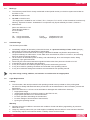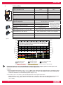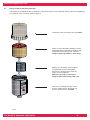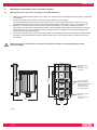
1
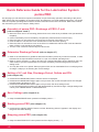
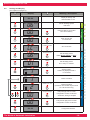
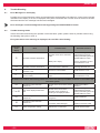
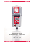
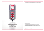
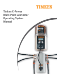
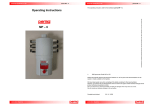
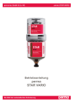
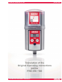
perma-tec GmbH & Co. KG
Translation of the
Original Operating Instructions
perma
PRO 250 / 500
The World of Automatic Lubrication
perma PRO
perma-tec GmbH & Co. KG
Lubrication System perma PRO
Protection cover
With bayonet catch for quick
opening/closing.
Content
Description of the filling date and the
contained lubricant.
PRO LC unit
(Lubrication Canister)
Cartridge, piston, spindle
filled with lubricant.
Type
Product type and size of PRO
LC unit
Red LED
Additional malfunction
indication.
Display
Informs about operating conditions,
malfunctions, settings, and the
lubricant volume left in the
PRO LC unit.
Push Button: ON/OFF/SELECT
To turn system ON or OFF and to
change settings.
Green LED
Additional indication of the current
operating condition.
Push Button: MODE/SAVE
Leads to the
Configuration Menu and saves
the selected settings.
Connector for distributor
PRO MP-6
Drive Unit
Contains electronics,
motor, and pump system.
Connection thread
G3/8 outside and G1/8 inside for
application into a lubrication point
or for connecting a grease tube.
Display
Configuration menu
For entering the settings.
Outlets 1 - 6
Shows activated outlets
99
Config.
Time PIN
Outlets
1
4
2
5
6
3
Number
Shows remaining volume,
discharge period, outlet no.,
PIN, and malfunction codes.
Days
Weeks
Months
LC2500
%Vol.
Remaining volume
of the PRO LC unit
Shows the lubricant
remaining in the PRO
LC unit in % volume.
Setting Mode
Displays the current setting in days,
weeks, or months.
Size of PRO LC unit
Displays volume of LC unit
(250 or 500 cc)
Ice icon
Indicates either that the temperature
fell below 0 °C/32 °F (icon blinking),
or that the low temperature shutoff
(below -20 °C/-4 °F) has turned the
system off (icon permanent).
Drive Unit
Battery Compartment
For insertion of battery
set
No function! Setting of
PRO LC unit size is done
via menu on the display.
Catch
For driving the spindle
Interlocking Teeth
To position the
PRO LC unit.
The World of Automatic Lubrication
PRO
Battery B
PRO Battery
B plus
-1-
Quick Reference Guide for the Lubrication System
perma PRO
On this page you will find some important information for quick and easy operation and setting of the perma
PRO. Before the first installation of the perma PRO, and whenever you need detailed instructions, you should
read the complete Operating Manual which contains information that must be observed. Make sure to follow
the instructions given in the chapter “Safety Notes”.
1
2
3
Assembly of perma PRO / Exchange of PRO LC unit
(refer to chapters 4 and 7)
♦ Mount the drive unit on the mounting plate and secure it at the three pre-drilled holes (see attached
template).
♦ Insert a new battery set into the battery compartment (follow directions of the arrows).
♦ Place the PRO LC unit inside the cover and remove the plug of the PRO LC unit.
♦ Push the PRO LC unit into the cover until lubricant comes out of the opening.
♦ Place the PRO LC unit with its cover on the drive-unit. Make sure that the catch locks and that the
teeth of PRO LC unit and drive unit interlock.
♦ Turn the cover clockwise until the bayonet catch locks.
Determine Discharge Period (refer to chapter 6.7)
♦ Refer to the manufacturer’s guidelines about the lubrication point that you want to lubricate, in order
to determine the required lubricant amount in cc per one hundred operating hours.
♦ Refer to chart 3 (chapter 6.7, chart 4) and find your required lubrication amount. Based on that, the
chart will show you the required PRO LC unit size, the setting of the discharge period, and the
setting mode.
♦ You may also refer to our perma Select program which can be downloaded from our web page free
of charge. It helps you in selecting the correct settings.
Setting of LC unit Size, Discharge Period, Outlets and PIN
(refer chapter 6.8)
♦ Hold down the MODE/SAVE button until the set time is displayed.
♦ Hold down the MODE/SAVE button again until you reach the current PIN (PIN cannot be changed
here/PIN setting at delivery is “00”).
♦ Hold down the MODE/SAVE button again until you reach the other setting menus:
LC unit, discharge period, outlets (only with attached MP-6), and PIN change. Change settings with
a short push of MODE/SAVE or ON/OFF/SELECT.
4
Save Settings (refer chapter 6.8)
5
Starting perma PRO (refer chapter 6.5)
6
Stopping perma PRO (refer chapter 6.6)
♦ Keep the MODE/SAVE button pressed until display shows “_ _”.
♦ Hold down the ON/OFF/SELECT button until the “Remaining Volume” appears in the display and
the green LED starts blinking.
♦ Keep the ON/OFF/SELECT button pressed until the display shows (“_ _”).
-2-
perma-tec GmbH & Co. KG
perma PRO
This operating manual is valid for the lubricator perma PRO with PRO LC units 250 cc and 500 cc.
©
2002 perma-tec GmbH & Co. KG
Without the specific approval of perma-tec GmbH & Co. KG no part of this documentation
can be copied or made available to third parties.
We have taken great care when compiling all the details contained in this documentation.
However, we cannot rule out discrepancies and we reserve the right to make technical
changes to the product without giving advance notice.
We do not assume any judicial responsibility or liability for damages which may ensue as
a result.
We will include any necessary changes in the next edition.
Compiled and printed:
11 / 02 / 2009
The World of Automatic Lubrication
perma PRO
Table of Contents
The lubrication system perma PRO
1
Quick reference guide
2
Content
3
1.
Various
1.1
Delivery / Content
1.2
Storage
1.3
Markings
1.4
Intended Usage
1.5
Legal Requirements
4
2.
Safety Instructions
2.1
Persons Responsible for Safety
2.2
General Safety Instructions
2.3
Safety Information for perma PRO
6
3.
Technical Data
3.1
Design of the perma PRO Lubricator
7
4.
Mounting and Assembly of the Lubrication System
4.1
Mounting the Drive Unit onto a Fixing Device for Wall-Mounting
4.2
Assembly of the Lubricator
9
5.
Display and Control Elements of the Lubrication System
5.1
Display Elements
5.2
Function Indication on the Display
5.3
Function Indication via the LEDs
5.4
Control Buttons
12
6.
Operation and Control
6.1
Preparations
6.2
Prior to Operation
6.3
Setting into Operation
6.4
During Operation
6.5
Switching the Lubrication System On
6.6
Switching the Lubrication System Off
6.7
Determining the Discharge Period
6.8
Settings and Display
6.9
Calculation of the Remaining Discharge Period
13
7.
Replacement of the PRO LC unit
7.1
Setting the Volume of the PRO LC unit
7.2
How to Replace the PRO LC unit
19
8.
Trouble Shooting
8.1
Error Messages on the Display
8.2
Trouble Shooting Guide
21
9.
Accessories and Spare Parts
22
10.
Disposal
24
11.
Service
24
12.
Declaration of conformity for perma PRO
25
-3-
perma-tec GmbH & Co. KG
1.
Various
About this Operating Manual
♦
♦
♦
This operating manual is intended for the safe operation of the perma PRO automatic lubricator.
It contains safety instructions which must be adhered to.
Everyone who works on or with the lubricator must have access to this operating manual during their shift.
They must also pay attention to all relevant instructions and notices.
The operating manual must always be kept complete and in easy to read condition.
Terms Used
♦
Lubrication system perma PRO
In the following text, the “lubrication system perma PRO” will either be called “lubricator” or by its
name “perma PRO”.
♦
Lubrication Canister
In the following text, the “Lubrication Canister” will be called PRO LC unit. The user can order the
PRO LC unit with different lubricants and in size 250 cc and 500 cc.
Usage of Safety Instructions
All safety instructions in this operating manual are standardized.
Danger Signs
This sign warns you of any danger to people’s health or to subjects.
Tips
This sign alerts you to application tips which will help you in doing certain tasks quicker and safer.
1.1
Delivery / Content
♦
♦
♦
♦
1.2
perma PRO will be delivered according to customer specifications in regards to type of grease and size
of PRO LC unit.
The user must only assemble it and adjust the desired settings.
Mounting device and screws included.
Operating instructions and EC Conformity Declaration included.
Upon delivery, make sure to check if the delivered goods correspond to your order. perma-tec GmbH
& Co. KG will not accept liability for subsequent claims of any shortcomings.
Please immediately forward any claims:
▪ of noticeable transport damage: directly to the forwarder.
▪ of noticeable faults, shortcomings or defects: directly to your perma distributor.
(3) (2)
Storage
When the lubricators are not immediately installed, you must ensure
appropriate storage conditions in dry, dust free places with a temperature
of +20 °C ± 5 °C (+68 °F ± 9 °F).
Make sure that PRO LC units and battery sets are not stored longer than one year.
Drive unit protection (1) during storage: do not remove cover disc (2) and plug (3)
until right before you intend to use the lubricator (see chapt. 6.2).
(1)
The World of Automatic Lubrication
-4-
perma PRO
1.3
Markings
♦
The lubricator perma PRO is clearly marked with a label (serial number) on the drive system and a label on
the PRO LC unit.
♦
CE mark on the drive unit.
♦
UL mark on the drive unit:
“This equipment is suitable for use in Class I, Div. 2, Groups A, B, C and D; or Non-Hazardous Locations only.
Warning - Explosions Hazard - Substitution of components may impair suitability for Class I, Division 2.”
♦
Manufacturer:
perma-tec GmbH & Co. KG
Hammelburger Straße 21
97717 Euerdorf
Germany
Tel: +49 (0) 9704 609-0
Fax: +49 (0) 9704 609-50
1.4
E–mail:
Homepage:
[email protected]
www.perma-tec.com
Intended Usage
The lubricator perma PRO
♦
♦
♦
♦
♦
♦
♦
♦
immediately supplies all lubrication points with lubricant, at a pressure build-up of max. 25 bar (360 psi.),
permanently, precisely and independent of temperature.
has passed the environmental audit according to standard EN 60068-2-6 (vibration test) without any
component damage or malfunctions. In test: PRO drive unit with MP-6, PRO LC unit 500 cc, and mounting
device in various mounting positions.
can be used for all lubrication points of sliding- and roller bearings, drive- and transport chains, sliding
guideways, open gears and seals.
should only be connected to/used with original lubrication tubes from perma-tec GmbH & Co. KG.
is intended for use on machinery and equipment.
is only to be used for the ordered purpose and purposes confirmed by perma-tec.
is only to be used for operating conditions recommended in this operating manual.
is only to be used with settings and variations recommended in this operating manual.
Any other usage, setting, addition, and variation is considered to be inappropriate!
1.5
Legal Requirements
Liability
♦
♦
The information, data and tips stated in this operating manual were up-to-data as of the printing date.
No claims for already delivered lubricators perma PRO can be made based on the information, pictures and
descriptions.
perma-tec GmbH & Co. KG can not be held liable for damages and malfunctions caused by:
▪ inappropriate usage;
▪ unauthorized alterations to the drive system or the PRO LC unit;
▪ inappropriate operations on or with the lubricator;
▪ incorrect operation and settings of the lubricator;
▪ incorrect settings of time and size of the lubricator;
▪ ignoring the operating manual.
Warranty
♦
♦
♦
Warranty terms and conditions: see terms and conditions of sale and delivery appertaining to perma-tec
GmbH & Co. KG.
Lodge any warranty claims with your local supplier immediately after the defect or error has been identified.
The warranty expires in all instances where no liability claims can be enforced.
-5-
perma-tec GmbH & Co. KG
2.
Safety Instructions
2.1
Persons Responsible for Safety
♦
2.2
General Safety Instructions
♦
♦
♦
♦
♦
♦
♦
2.3
The operator or his safety officer must warrant,
▪
that all the relevant regulations, instructions and laws are adhered to;
▪
that only qualified personnel will work with and on the lubricator;
▪
that unauthorized personnel are not allowed to work with and on the lubricator;
▪
that the safety regulations are adhered to when mounting the lubricator or during maintenance.
We are not laying claim to completeness in regards to these safety instructions. Please contact perma-tec
Customer Service if you have any questions or problems.
At the time of delivery the lubricator is in line with state-of-the-art technology and in principle is considered to
be safe to operate.
Dangers emanate from the lubricator for persons, the lubricator itself and for other material assets of the
operator if:
▪ unqualified personnel operates the lubricator;
▪ the lubricator is used inappropriately and for operations that it was not intended to be used for;
▪ the lubricator setting / variation is incorrect;
▪ the lubricator is opened by force while in operation;
▪ the lubricator is not mounted with the perma mounting device;
▪ the tube connection to the lubrication point was not carried out and attached correctly;
Operate the lubricator only when it is in perfect condition.
Retrofitting, changing, or reconstructing the lubricator is prohibited. perma-tec must be consulted first.
Only original tube connections and connectors from perma-tec can be used on or with the lubrication system
since these will withhold high pressures of up to 25 bar (360psi).
Ambient media, especially chemically aggressive substances, can attack seals and plastic.
Safety Information for perma PRO
Safety during Installation and Maintenance
♦
♦
♦
Ensure that all workstations and traffic routes are clean and safe!
Ensure that the relevant regulations and guidelines are adhered to when the installation or maintenance work
is carried out in places where danger of falling exists.
Ensure that the relevant safety and operating instructions are observed when the lubricators are installed or
serviced on machines or in factories (i.e. to stop the machine).
Safety when Handling the PRO LC unit
♦
♦
♦
♦
♦
♦
Avoid contact of lubricant with eyes, skin, and clothing!
Avoid swallowing of lubricant!
Prevent lubricant from getting into soil or sewer system!
Observe safety data sheets of lubricants!
You may also download data sheets of lubricants supplied by perma-tec from perma-tec´s web page
(www.perma-tec.com) or ask your local supplier.
Lubricant on traffic ways will increase the danger of slipping! Therefore, immediately clean lubricant from floors
with special cleaner.
Only use original PRO LC units from perma-tec!
Safety when Handling Batteries!
♦
♦
♦
♦
♦
♦
Avoid contact of battery substances with eyes, skin and clothing!
Avoid swallowing any leaking battery substances!
Do not expose batteries to extreme heat and do not throw into open fire!
Do not recharge batteries!
Ensure that regulations for waste disposal of batteries are observed!
Only use original battery sets from perma-tec!
The World of Automatic Lubrication
-6-
perma PRO
Technical Data
PRO 250
PRO 500
250 cc
500 cc
Length (L)
210 mm
260 mm
Diameter (D)
92 mm
92 mm
Weight, empty
1.30 kg
1.37 kg
Weight, filled with SF04
1.53 kg
1.82 kg
1 day to 24 months
1 day to 12 months
Volume of the PRO LC unit
212.44
L
92.11
D
Discharge period
Discharged volume per lubrication impulse
0.5 cc
Application temperature
- 20 °C to +60 °C / - 4 °F to +140 °F
Maximum pressure build-up
25 bar / 360 psi
Maximum tube length (inner-Ø 5mm)
5m
Greases up to rated
consistency NLGI 2
Lubricants
Power supply (0 °C to +60 °C / +32 °F to +140 °F)
Battery set PRO B (3 V alkaline manganese, not rechargeable)
Power supply, low temperature
(- 20 °C to +60 °C / - 4 °F to +140 °F)
Battery set PRO B PLUS (3 V lithium, not rechargeable)
Emission sound pressure level
< 70 dB(A)
Connection thread
G3/8 outside – G1/8 inside
Protection class
figure 1
Combination of these MaximumValues can only be realized by
temperatures of ≥ 20 °C/ 68 °F.
At lower temperatures, the
application is limited according
to the diagram below.
IP 54
chart 1
60°C
140°F
Diagram showing dependency of application temperature
and tube length (inner-Ø 5 mm) for perma-standard grease
and low temperature grease
50°C
Temperature in °C
40°C
120°F
100°F
30°C
80°F
4
20°C
60°F
10°C
0°C
3
1
-10°C
40°F
20°F
2
-20°C
0
1
Application area for
standard grease
2
3
tube length in meter
Application area for
Low temp. grease
Temperature in °F
3.
0°F
4
5
out of specification range
no warranty!
The dashed standard grease- and dotted low temperature-lines show the maximum values allowed.
If your application is out of the specification range shown in this diagram, please contact your local
distributor. perma-tec cannot be held liable for these applications.
Example:
1. The application temperature is +5 °C / +41 °F. What is the maximum tube length allowed for standard grease?
Correct Answer: 3 m max. tube length for standard grease, 5 m max. tube length for low temp. grease (arrow
1 meets the dashed line of the standard grease range at 3 m).
2. You want to use a 4 m tube. Up to which temperature can the system be used?
Correct Answer: +10 °C / 50 °F with standard grease -5 °C / 23 °F with low temp. grease (arrow 3 meets the
dotted line of low temp. grease at the -5 °C mark; and the dashed line of the standard grease at the
+10 °C mark).
-7-
perma-tec GmbH & Co. KG
3.1
Design of the perma PRO Lubricator
Lubricators are available as 250 cc and 500 cc versions and they can be supplied with the lubricant requested by
the customer. They consist of (refer to figure 2):
Protection cover for the drive unit, re-usable.
PRO LC unit (Lubrication Canister), can be
supplied as 250 cc and 500 cc versions with
the lubricant requested by the customer.
Usage of perma pro PRO LC units only!
Battery set, consisting of two batteries.
The batteries are not rechargeable
and must be changed every time the
PRO LC unit is replaced.
Batteries can only be used once!
Usage of perma-tec battery sets only!
Drive unit, consisting of a gear motor,
a pump system and an electronic unit
for the control system, re-usable.
figure 2
The World of Automatic Lubrication
-8-
perma PRO
4.
Mounting and Assembly of the Lubrication System
4.1
Mounting the Drive Unit onto a Fixing Device for Wall-Mounting
♦
♦
♦
♦
Attach the supplied mounting device to the drive unit using the two enclosed hex head bolts (M6 x 16) and the
two washers.
Screw the mounting device with the drive unit onto a support of your system.
The boring template of the three mounting screws (141.5 x 45) can be seen below in picture 3 or on the
template that is included. You have to use at least three hexagon screws M6 x 25 (e.g. on metal ground).
Before you connect the outlet of the drive unit to the lubricant tube, you have to make sure that the
lubrication points and the complete lubricant tube is pre-lubricated with the same lubricant that is contained
in the PRO LC unit. For that, perma-tec offers a 400 g lubrication cartridge for manually-operated grease
presses with the requested lubricant.
Connect the lubricant tube (connection G3/8 outside or G1/8 inside) to the outlet of the drive unit and install
the tube correctly between the outlet and the lubrication point. The lubricant tube must not be longer than
five meters.
Make sure that you assemble the connections and lubricant tubes correctly and tightly to avoid
possible leakage.
141.5
141.5
Hexagon screws
M6 x 25
(for wall mounting
on metal)
2 hex head bolts
M6 x 16, maximum
torque 3 Nm (supplied
for attaching the
perma PRO to the
mounting device)
2 hexagon screws
M6 x 25
(for wall mounting
on metal)
113.3
113
45
45
figure 3
-9-
perma-tec GmbH & Co. KG
4.2
Assembly of the Lubricator
a)
♦
Insert the battery set into the drive unit (according to the direction of the arrow on the label).
No function!
Setting of PRO LC unit size is done via
menu on display
Battery set
figure 4
Catch
Interlocking teeth
b)
♦
Place the PRO LC unit inside the protection cover and remove the plug of the PRO LC unit (refer to figure 5).
Protection cover
PRO LC unit
Plug
figure 5
The World of Automatic Lubrication
- 10 -
perma PRO
c)
♦
Push the PRO LC unit into the protection cover until lubricant comes out of the opening (refer to figure 6).
figure 6
d)
♦
♦
Place the PRO LC unit with its protection cover on the drive-unit. Make sure that the catch locks and that the
teeth of the PRO LC unit and the drive unit interlock (refer to figure 4 and figure 7).
Turn the cover clockwise until the bayonet catch locks.
figure 7
- 11 -
perma-tec GmbH & Co. KG
5.
Display and Control Elements of the Lubrication System
5.1
Display Elements
The operating status of the lubricator can be determined via the green or the red LED and via the display
at the control unit (refer to figure 8) of the perma PRO.
The perma PRO offers a menu-guided setting. Changes of the settings are shown on the display. Error
messages, e.g. in case the pressure in the lubricant tube gets too high, are also indicated on the display.
LCD
push-button
MODE
SAVE
Red LED
Green LED
push-button
ON/OFF
SELECT
Connector for
distributor MP-6
figure 8
5.2
Function Indication on the Display
The display is located on the control unit of the perma PRO (refer to figure 8, chapter 5.1).
The display shows settings, operating conditions and error messages of the lubricator.
In case of an error free operation of the lubrication system, the display shows the remaining volume of the
mounted PRO LC unit in percent volume (% Vol.). Figure 9 shows an example of the displayed information
if the PRO LC 500-unit is new and full.
99
LC2500
%Vol.
figure 9
The display cannot be switched off by the operator. If the lubrication system is switched off, the display
will always show two lines (see figure 10 below).
––
figure 10
5.3
Function Indication via the LEDs
LED
Signal
Signal Length
Explanation
green
flash
every 10 seconds
operation (OK)
red
flash
every 3 seconds
error / malfunction
green and red
flash
every 3 seconds
PRO LC unit empty
green
light
permanently
Lubricator is discharging
green and red
none
none
Lubricator switched off or battery low
chart 2
The World of Automatic Lubrication
- 12 -
perma PRO
5.4
Control Buttons
There are two push-buttons on the control unit (refer to figure 8) which can be used for a menu-guided change of
the settings.
♦
♦
With the MODE/SAVE button (refer to figure 11), you can reach the configuration menu, change the mode
and save the modified settings for further operation.
With the ON/OFF SELECT button (refer to figure 12) you can do the following: turn lubricator On/Off, increase
discharge period (Days, Weeks, Months - each time you press the button increases the discharge period by
one calendar unit), change PRO LC unit size, activate MP-6 outlets and set PIN.
PRESS
Short
Short
BUTTON
MODE
SAVE
ON/OFF
SELECT
figure 11
Selection
in current
display
FUNCTION
Long >4 sec. until
the display content
changes completely
Long >4 sec. until
the display content
changes completely
MODE
SAVE
ON/OFF
SELECT
figure 12
figure 11
figure 12
Changing of
values
Moves to new menu and
saves selected values
Returns to original menu
without saving changes
chart 3, figure 11, figure 12
6.
Operation and Control
6.1
Preparations
♦
♦
♦
♦
Prior to the installation of the lubricator, the lubrication point and the complete connection tube must be
sufficiently prelubricated with the same lubricant that the PRO LC unit contains. For this, perma-tec offers a
400 g lubrication cartridge for grease presses with the corresponding lubricant (refer to chart 8b, chapter 9).
When installing the perma PRO, the supplied perma-tec mounting device should be used.
The lubricant tube must be installed and mounted correctly. The length of the lubricant tube may not exceed a
maximum of 5 meters and the tube must be a perma-tec product.
Please check if the thread of the perma PRO (G3/8 or G1/8) corresponds to the connection thread of the
lubrication point. If this is not the case, you can order a corresponding reducer or other parts from the perma
accessory range.
For the initial setting into operation of a perma PRO, the pump system in the drive unit is pre-filled with
SF04 from perma’s standard range of lubricants. An exception is made with regard to lubricants for the food
industry. A complete discharge of this pump filling is guaranteed after approx. 10 discharges (carry out additional
discharges, if necessary).
6.2
Prior to Operation
♦
♦
♦
♦
♦
Check all parts of the lubricator for obvious damages!
Is the new PRO LC unit filled with the required lubricant?
Did you insert a new battery set?
Has the cover disc with plug been removed from drive unit (see chapter 1.2)?
Did you assemble and mount all of the parts correctly and tightly?
- 13 -
perma-tec GmbH & Co. KG
6.3
Setting into Operation
♦
♦
♦
♦
♦
♦
If necessary, mount the drive unit onto a fixing device for wall-mounting (refer to chapter 4.1).
Insert the battery set into the drive unit and the PRO LC unit into the protection cover and close the complete
system (refer to chapters 4.2 b - d).
Determine the discharge period (refer to chapter 6.7).
Set volume of PRO LC unit, discharge period, outlets of MP-6, and the PIN via buttons on display (refer to
chapter 6.8).
Switch-on the lubrication system (refer to chapter 6.5).
Carry out an additional discharge (refer to chapter 6.8).
If the drive motor has started and the green LED is lit, the lubricator has started to discharge. The display
indicates the remaining volume (% Vol.) of the PRO LC unit.
The operator must always check the customer-specific settings and if necessary change them before the
lubricator is set into operation!
6.4
During Operation
♦
♦
♦
♦
♦
Carry out regular inspections during the operation. You should pay special attention with regard to leakage and
to the condition of the lubricator!
Check the condition of the lubricant tube and the connections regularly!
Check the filling level of the transparent PRO LC unit regularly!
After one or several additional discharges, you have to calculate the reduced discharge period and note this on
your lubrication and maintenance schedule.
If a malfunction is indicated on the display, you can determine the cause using the trouble shooting guide (refer
to chart 7, chapter 8.2). If the fault cannot be fixed, please contact your supplier for technical support.
Additional discharges and long machine standstills must always be taken into account with regard to the
remaining discharge period of the lubricator.
6.5
Switching the Lubrication System On
To switch the lubrication system on (refer to figure 13), keep the ON/OFF/SELECT button pressed until the
indication (“_ _”) on the display is replaced by an indication of the remaining volume – e.g. 99 % VOL (with a new
PRO LC unit) – and the green LED starts blinking.
––
ON/OFF
SELECT
99
LC2500
%Vol.
figure 13
6.6
Switching the Lubrication System Off
To switch the lubrication system off (refer to figure 14), keep the ON/OFF/SELECT button pressed until the
display no longer indicates the remaining volume – % VOL – but indicates (“_ _”) instead. When the lubrication
system is switched off, all of the settings are saved. This means that if you start the lubricator again, it will take up
the operation at the point where it had been switched off.
99
LC2500
%Vol.
ON/OFF
SELECT
––
figure 14
The World of Automatic Lubrication
- 14 -
perma PRO
6.7
Determining the Discharge Period
The discharge period is automatically factory-set to six months according to the supplied PRO LC unit.
Upon request, a factory-setting of the discharge period required by the customer is also possible. The size of the
PRO LC unit is taken into account.
If you want to determine the discharge period, you need to know the required amount of the lubricant in cubic
centimeters for 100 operating hours (cc/100 h). This information can be taken from the technical documents of
the manufacturer of the lubrication point.
With this information, you can determine the discharge period using the following chart (chart 4).
Average discharge volume in cc per 100 operating hours
PRO LC unit
250
500
Setting mode
Setting point
Discharge period
Days
Weeks
Months
Days
Weeks
Months
1
1041.7
148.8
34.3
2083.3
297.6
68.5
2
520.8
74.4
17.1
1041.7
148.8
34.3
3
347.2
49.6
11.4
694.4
99.2
22.8
4
260.4
37.2
8.6
520.8
74.4
17.1
5
208.3
29.8
6.9
416.7
59.5
13.7
6
173.6
24.8
5.7
347.2
49.6
11.4
7
148.8
21.3
4.9
297.6
42.5
9.8
8
130.2
18.6
4.3
260.4
37.2
8.6
9
115.7
16.5
3.8
231.5
33.1
7.6
10
104.2
14.9
3.4
208.3
29.8
6.9
11
94.7
13.5
3.1
189.4
27.1
6.2
12
86.8
12.4
2.9
173.6
24.8
5.7
13
80.1
11.4
2.6
160.3
22.9
--
14
74.4
10.6
2.4
148.8
21.3
--
15
69.4
9.9
2.3
138.9
19.8
--
16
65.1
9.3
2.1
130.2
18.6
--
17
61.3
8.8
2.0
122.5
17.5
--
18
57.9
8.3
1.9
115.7
16.5
--
19
54.8
7.8
1.8
109.6
15.7
--
20
52.1
7.4
1.7
104.2
14.9
--
21
49.6
7.1
1.6
99.2
14.2
--
22
47.3
6.8
1.6
94.7
13.5
--
23
45.3
6.5
1.5
90.6
12.9
--
24
43.4
6.2
1.4
86.8
12.4
--
25
41.7
--
--
83.3
--
--
26
40.1
--
--
80.1
--
--
27
38.6
--
--
77.2
--
--
28
37.2
--
--
74.4
--
--
29
35.9
--
--
71.8
--
--
30
34.7
--
--
69.4
--
--
chart 4
Please take into account that in case of one or several additional discharges, the remaining discharge period
of the lubrication system must be recalculated (refer to chapter 6.7). This also applies in case of a cut-off of the
lubrication system due to a long machine standstill (e.g. weekends or annual holidays). You should also note the
result of your calculation of the remaining discharge period in your lubrication and maintenance schedule.
The perma SELECT software helps you to determine the discharge period.
Visit our website www.perma-tec.com for a free download of this software.
- 15 -
perma-tec GmbH & Co. KG
Settings and Display
(see caption on page 17)
Display
Change second digit
Config.
MODE
SAVE
Config.
Time
MODE
SAVE
Config.
Time
MODE
SAVE
Config.
Outlets
1
4
5
2
5
3
6
MODE
SAVE
Config.
Outlets
1
4
5
2
5
3
6
Config.
Outlets
1
4
2
5
3
6
MODE
SAVE
ON/OFF
SELECT
Change from
LC500 to LC250
Set LC unit size
LC2500
ON/OFF
SELECT
Change Months
Months
ON/OFF
SELECT
Change Days or
Weeks
Weeks
MODE
SAVE
Outlet 1 On / Off
ON/OFF
SELECT
MODE
SAVE
Set discharge period:
Go to “Days” or “Weeks”
Activate outlets:
Activate outlet 1
Outlets only displayed if MP-6
is connected
Outlet 1 activated
Outlet 2 On / Off
ON/OFF
SELECT
Change first digit
ON/OFF
SELECT
Outlet 2 activated
(if desired, other outlets may be turned
On / Off the same way)
PIN (first digit) enter for initial
configuration or after a PIN-reset
– otherwise, setting is complete
Change second digit
Config.
PIN
MODE
SAVE
Set discharge period:
Either Months, Weeks, or Days
ON/OFF
SELECT
Config.
PIN
MODE
SAVE
Enter second digit
of current PIN
LC
MODE
SAVE
ON/OFF
SELECT
PIN (second digit) enter for initial
configuration or after a PIN-reset
Configuration finished
chart 5
The World of Automatic Lubrication
- 16 -
M E N U
PIN
C O N F I G U R A T I O N
ON/OFF
SELECT
Enter first digit of current PIN
PIN “00” at delivery
PIN Entry
Change first digit
Info
Shows discharge period
PIN-reset
Months
I N T R O
Display at delivery with
attached PRO LC unit
PIN
MODE
SAVE
Meaning / Description
Time
Time
MODE
SAVE
––
06
00
00
LC
06
0I
I
I
2
00
00
––
ON/OFF
SELECT
Outlets
MODE
SAVE
PIN
6.8
perma PRO
Caption for Chart on Left Side
Instructions should be followed from top to bottom and from left to right (also refer to chart. 3). The instructions
correspond to the operating sequence on the turned-off lubrication system perma PRO. Configuration is also
possible if perma PRO is On.
Function
short push
long push
blinking display
Go to
Symbol
chart 6
Configuration sections (see vertical bar, chart 5)
INTRO
INTRO informs (INFO) and asks for the current PIN (PIN-entry). Settings can be changed in the configuration
menu with its different sections (LC, Time, Outlets, PIN).
CONFIGURATION MENUE
LC
You can change the PRO LC unit size from LC250 to LC500 and back by pushing the ON/OFF/SELECT button
(refer to chapter 7.1 and 7.2).
Time
The discharge period can only be set in one type of calendar unit (i.e. either Months, Weeks or Days). When the
highest unit size is reached, counting starts again with number “0 I ”.
Outlets
If a MP-6 distributor is connected, outlets 1 - 6 can be set individually. The activated outlets 1 - 6 are displayed
with a filled-in square in the display (please refer to the operating instruction of the MP-6 distributor for more
details).
PIN
We strongly suggest to enter a personal PIN in order to protect your settings from unauthorized access. The PIN
can only be changed during initial configuration or after a PIN-reset. A PIN-reset (short push of buttons:
left-left-right-right-left in the INTRO-Info-menu) changes your personal PIN back to “00”. The PIN-reset was
successful when the displayed time disappears for a second and then comes back on. All other settings remain
unchanged.
Save or Reject Changed Settings
The display settings can be saved with a long push of the MODE/SAVE button. If you do not want to save your
changes to settings that are currently displayed in the configuration menu (LC, Time, Outlets, PIN), press the
ON/OFF/SELECT button until the display shows either (“––”) for Off or the remaining volume of the PRO LC unit
in % VOL. All other settings and already saved changes remain valid.
Automatic Termination of the Configuration Mode
If you do not press a button in the configuration menu for 180 seconds, the control system is automatically
switching back to the previously set mode (“On” or “Off”) without saving the changes. All other settings and
already saved changes remain valid.
Additional Discharge
With an additional discharge, a lubrication point can be supplied with an additional amount of the lubricant.
For an additional discharge, the lubrication system must be switched on (display shows remaining volume) and
you have to press both buttons simultaneously and hold them down (refer to figure 15).
99
LC2500
MODE
SAVE
ON/OFF
SELECT
%Vol.
figure 15
Lubricator On
For an additional discharge, press both buttons at the
same time and hold them down.
An additional discharge is only possible at temperatures above 0 °C / 32 °F (figure 16, ice crystal is not visible)
and when the lubrication system is not currently conducting a regular discharge.
Every additional discharge reduces the remaining discharge period since an increased amount of the lubricant
has been supplied. This must be taken into account in your lubrication and maintenance schedule. A calculation is
possible with the formula from chapter 6.9 and with the remaining volume which is displayed.
The time between two additional discharges is 30 seconds. Each additional long push of both buttons
(simultaneously, figure 15) during this time is being registered and will lead to even more additional
discharges. The system remembers a max. of 5 additional discharges.
- 17 -
perma-tec GmbH & Co. KG
Low-Temperature Cut-Off of the Lubrication System
The temperature range from 0 °C to -19 °C (32 °F to -2.2 °F) is indicated by a blinking ice crystal symbol
(refer to figure 16).
In this temperature range the lubrication system perma PRO continues to operate without interruption.
Please note, that in this temperature range an additional discharge is not possible!
89
LC2500
%Vol.
figure 16
Display with a blinking ice crystal (in this example with 89 % Vol.)
In order to protect the system from damage, the low-temperature cut-off of the lubrication system is automatically
carried out by the control system and the built-in temperature sensor.
If the temperature reaches or falls below -20 °C (-4 °F), the lubricator is switched off by the low-temperature
cut-off and the ice crystal symbol is permanently indicated on the display. The remaining volume is still displayed
in % Vol.
From this time onwards, the lubricant is no longer discharged. You have to take this fact into account if
your system continues to operate in order to prevent damages!
As soon as the temperature rises and reaches -19 °C (-2.2 °F) or higher, the control system switches the
lubrication system on.
The display shows the remaining volume and the blinking ice icon.
All discharges (except additional discharges), accumulated during the shut-off, will be caught up when
the system continues operation (at a max. of two additional discharges with every regular discharge).
6.9
Calculation of the Remaining Discharge Period
Please note, that in case of one or several additional discharges, the remaining discharge period of the lubrication
system must be recalculated. This also applies in case of a cut-off of the lubrication system due to a long
machine standstill (e.g. weekends or annual holidays) or in case of a low-temperature cut-off carried out by the
system if temperatures reach -20 °C (-4 °F).
You should also note the result of your calculation of the remaining discharge period in your lubrication and
maintenance schedule.
SDP * RV
Formula: RDP =
100
SDP: Set Discharge Period of the lubricator (days, weeks, months)
RV: Remaining Volume (displayed in % Vol.)
RDP: Remaining discharge period (days, weeks, months depending on SDP)
Example of a Calculation of the Remaining Discharge Period
The perma PRO with a 250 cc PRO LC unit was originally set to a discharge period (SDP) of eight months,
since the lubrication point needs 4.3 cc lubricant /100 h. After two months, the perma PRO indicates a remaining
volume (RV) of 75 % Vol. At this point, the lubricator is switched off for six weeks (e.g. machine standstill). When
it is switched on again, you would like to determine when the PRO LC unit will be empty.
SDP * RV
RDP =
8 * 75
=
100
600
=
100
=6
100
This results in a remaining discharge period of six months. After these six months, the PRO LC unit will be empty
and must be replaced by a new one.
The World of Automatic Lubrication
- 18 -
perma PRO
7.
Replacement of the PRO LC unit
The Following Must Always Be Taken into Account
If the replacement of an empty PRO LC unit becomes necessary, it will be indicated by a simultaneous blinking of
the red and the green LED. Additionally, the display indicates that the PRO LC unit is empty (refer to figure 17).
00
LC2500
%Vol.
figure 17
If you replace the PRO LC unit, you also have to change the battery set. Otherwise, the correct operation of
the lubricator cannot be guaranteed!
If you replace the PRO LC unit by a PRO LC unit of a different size, a corresponding protection cover (refer
to chart 8a, chapter 9) must be used.
Since the drive unit and the control board must be protected against moisture, an exchange may only be
carried out in dry conditions!
After the installation of the new PRO LC unit, the control system continues to operate using the previously valid
setting of the discharge period.
7.1
Setting the Volume of the PRO LC unit
The size of the PRO LC unit must be set in the configuration menu with the two buttons on the drive unit (see
figure 18). Please also refer to the operating chart (chart 5, chapter 6.8).
ATTENTION!
If the displayed setting does not correspond with the attached PRO LC unit size it will result in incorrect
discharge amounts and wrong signals in the display (Display, LEDs).
Config.
figure 18
LC
Config.
LC2500
or
LC
LC2500
ATTENTION!
Whenever a PRO LC unit is removed from the lubricator and is replaced by another LC unit, the control system
assumes that a new, completely filled PRO LC unit was attached.
Therefore NEVER attach a PRO LC unit that is not completely full!
- 19 -
perma-tec GmbH & Co. KG
7.2
How to Replace the PRO LC unit
Drive system and circuit board must be protected from moisture. Exchanges should only be done in a dry place
and it must be ensured that no moisture enters the drive unit.
a) Turn the protection cover on the drive unit counter-clockwise and remove it.
b) Remove the empty PRO LC unit. The display indicates “LC” and the red LED is blinking.
c) Remove the used battery set from the drive unit.
d) Insert the new battery set into the drive unit. Follow the directions of the arrows.
e) Remove the plug of the PRO LC unit (refer to figure 5, chapter 4.2).
f)
Push the PRO LC unit into the protection cover until lubricant comes out of the opening
(refer to figure 6, chapter 4).
g) Place the new PRO LC unit on the drive unit, turn it until the catch locks and the teeth of the PRO LC unit
and the drive unit interlock. The control system automatically recognizes the new PRO LC unit.
The display indicates “_ _” if the perma PRO was switched off prior to the replacement of the PRO LC unit.
Or it indicates “99 % Vol.” if the perma PRO was switched on before the replacement.
You should only use completely full perma-tec PRO LC units, in order to guarantee a trouble-free operation.
h) The lubrication system continues to operate with the previous setting of the discharge period.
i)
If required, change lubricator settings (see chapter 6.8).
If the lubricator was ON before changing the LC unit, it will automatically resume operation with existing
settings. If the lubricator was OFF, it must be turned ON (refer to figure 13, chapter 6.5).
The World of Automatic Lubrication
- 20 -
perma PRO
8.
Trouble Shooting
8.1
Error Messages on the Display
Possible errors of the lubrication system and the application are detected by the electronic control system and are
indicated on the display. If an error is displayed, the system is switched OFF until the cause of the error has been
eliminated and the error message has been acknowledged.
Error messages are acknowledged and reset by pushing the ON/OFF/SELECT button.
8.2
Trouble Shooting Guide
If there are malfunctions during the operation of the lubrication system, please check for possible causes using
the following chart (refer to chart 7).
Every time that an error message is displayed, the red LED is also blinking.
Indication
of the
display
EI
Error
Possible cause
Remedial measures
Excess motor current of the
lubricator motor due to a blocked
outlet
Clear the blockage and
acknowledge the fault by
pushing and holding down the
ON/OFF/SELECT button
Battery set is empty
Insert a new battery set and
use a full PRO LC unit
Lubricator has been switched off
E4
Lubricator has been switched off
Drive mechanism is defective
Exchange the drive unit
LC
System does not detect
the PRO LC unit
No PRO LC unit installed
Install an PRO LC unit
L8
No power supplied to the system
from the battery
No battery inserted or battery set
empty
Insert a new battery set and
use a full PRO LC unit
In addition to the above, the following malfunctions can occur when a perma MP-6 distributor is connected to the
lubrication system:
Lubrication system has been
switched off
Excess motor current of the perma
MP-6
Replace perma MP-6
distributor
Error at the displayed lubrication
point
Excess motor current of the
lubricator motor caused by a
blocking of the displayed outlet
Clear the blockage and
acknowledge the fault by
pushing and holding down the
ON/OFF/SELECT button
E2
Lubrication system has been
switched off
Outlets of distributor not correctly
recognized
Replace distributor
E3
Lubrication system has been
switched off
Timeout while activating distributor
Replace distributor
Connection cable damaged
Replace connection cable
E5
Outlet configuration missing
Outlets were not activated
Activate desired outlets
E0
F I to f6
chart 7
- 21 -
perma-tec GmbH & Co. KG
9.
Accessories and Spare Parts
Due to the high pressure of up to 25 bar (360 psi), you should only use genuine spare parts and accessories
from perma-tec in order to ensure a reliable operation of the distributor and the complete lubrication system.
This especially applies to connections and lubricant tubes.
Spare parts and accessories must meet the technical requirements!
This is always guaranteed with genuine spare parts and accessories from perma-tec.
Spare parts
PRO LC 250
filled with lubricant
Part. No.
Illustration
222 XXXX*) 608
*) XXXX = grease number
PRO LC 500
filled with lubricant
223 XXXX*) 609
*) XXXX = grease number
PRO Cover for LC 250
made of transparent plastic
2299 101 000
PRO Cover for LC 250
made of aluminium for applications
with ester-containing lubricants
2299 102 001
PRO Cover for LC 500
made of transparent plastic
2299 102 000
PRO Cover for LC 500
made of aluminium for applications
with ester-containing lubricants
2299 102 002
PRO Battery B
(0 °C to +60 °C / 32 °F to 140 °F)
2299 001 606
PRO Battery B plus
(- 20 °C to +60 °C / - 4 °F to +140 °F)
2299 002 607
chart 8a
The World of Automatic Lubrication
- 22 -
perma PRO
Spare parts
Part. No.
perma PRO Mounting Device
27 008 007
Grease cartridge 400 g filled with
to be used for pre-filling grease
lines with a grease gun
on request
Tube Connector G1/8a for tube
aØ 8 mm straight
27 008 010
Tube Connector G1/8a for tube
aØ 8 mm 90°
27 008 011
PRO tube 8 x 1.5 (inner-Ø 5 mm)
with different lengths
27 008 009
Reducer G3/8 – G1/4
27 008 017
CD ROM with SELECT software
(calculation of the lubricant amount),
lubrication and maintenance schedule and
operating instructions as PDF file
on request
chart 8b
- 23 -
Illustration
perma-tec GmbH & Co. KG
10.
Disposal
Help us in protecting the environment and saving resources by recycling valuable raw material.
Please follow your local waste disposal regulations.
11.
Service
♦
Please contact your local supplier for availability and cost of the following:
▪
Returning of the empty lubricator for environmentally safe recycling or disposal.
or:
▪
▪
▪
exchange of battery set.
exchange of PRO LC unit.
to pre-set lubricator (LC/lubrication period/outlets)
The World of Automatic Lubrication
- 24 -
perma PRO
12.
Declaration of conformity for perma PRO
EC declaration of conformity
- according to the Machinery Directive 98/37/EC[1] and according to EMV (Electromagnetic Compatibility) –
Directive 2004/108/EC
- according to the Machinery Directive 2006/42/EC[2] and according to EMV (Electromagnetic Compatibility) –
Directive 2004/108/EC
The manufacturer
perma-tec GmbH & Co. KG
Hammelburger Straße 21
97717 Euerdorf
Germany
hereby declares that the product as described in the given statement conforms to the regulations appertaining
to the directives referred to above, including any amendments thereto which are in force at the time of the
declaration.
Product description:
Product name:
Type:
Automatic lubrication system
Lubrication system perma PRO
perma PRO 250 and perma PRO 500
The following harmonised standards were applied:
EN ISO 12100-1:2003
Safety of machinery – basic concepts, general terms of reference as regards
design and construction – Section 1: Basic Terminology, Methodology
EN ISO 12100- 2:2003
Safety of machinery – basic concepts, general terms of reference as regards
design and construction – Section 2: Technical terms of reference
EN 60204 – 1:2006
Machinery’s electrical equipment
Euerdorf, 11 February 2009
perma-tec GmbH & Co. KG
Walter Graf, Managing Director
Egon Eisenbacher, Technical management
and authorized documentation representative
(see manufacturer address)
This declaration certifies conformity to the directives referred to but it is not a warranty of qualities. The safety
instructions of the operating manual are to be observed.
1.
2.
Directive 98/37/EC is valid until and including the 28th of December 2009.
Directive 2006/42/EC is valid as of 29 December 2009.
- 25 -
perma-tec GmbH & Co. KG
perma PRO
perma-tec GmbH & Co. KG
Hammelburger Str. 21
97717 Euerdorf
Germany
Tel: +49 (0) 9704 609-0
Fax: +49 (0) 9704 609-50
E-mail: [email protected]
Homepage: www.perma-tec.com
The World of Automatic Lubrication
09/02/11