1
420 Plus
HMI Digital Weight Indicator
Version 1.14
Installation Manual
85127
Contents
About This Manual ................................................................................................................................... 1
1.0
Introduction.................................................................................................................................. 1
1.1
1.2
1.3
1.4
2.0
Operating Modes . . . . . . . . . . . . . . . . . . . . . . . . . . . . . . . . . . . . . . . . . . . . . . . . . . . . . . . . . . . . . . . .
Front Panel Keypad . . . . . . . . . . . . . . . . . . . . . . . . . . . . . . . . . . . . . . . . . . . . . . . . . . . . . . . . . . . . . .
LED Annunciators. . . . . . . . . . . . . . . . . . . . . . . . . . . . . . . . . . . . . . . . . . . . . . . . . . . . . . . . . . . . . . . .
Indicator Operations . . . . . . . . . . . . . . . . . . . . . . . . . . . . . . . . . . . . . . . . . . . . . . . . . . . . . . . . . . . . . .
1
2
2
3
1.4.1
1.4.2
1.4.3
1.4.4
1.4.5
1.4.6
1.4.7
1.4.8
1.4.9
1.4.10
1.4.11
1.4.12
1.4.13
1.4.14
3
3
3
3
3
3
4
4
4
4
4
4
4
4
Toggle Gross/Net Mode/Piece Count . . . . . . . . . . . . . . . . . . . . . . . . . . . . . . . . . . . . . . . . . . . . . . . . . .
Toggle Units . . . . . . . . . . . . . . . . . . . . . . . . . . . . . . . . . . . . . . . . . . . . . . . . . . . . . . . . . . . . . . . . . . . . .
Zero Scale. . . . . . . . . . . . . . . . . . . . . . . . . . . . . . . . . . . . . . . . . . . . . . . . . . . . . . . . . . . . . . . . . . . . . . .
Acquire Tare . . . . . . . . . . . . . . . . . . . . . . . . . . . . . . . . . . . . . . . . . . . . . . . . . . . . . . . . . . . . . . . . . . . . .
Enter Tare (Keyed Tare) . . . . . . . . . . . . . . . . . . . . . . . . . . . . . . . . . . . . . . . . . . . . . . . . . . . . . . . . . . . . .
Remove Stored Tare Value . . . . . . . . . . . . . . . . . . . . . . . . . . . . . . . . . . . . . . . . . . . . . . . . . . . . . . . . . .
Acquire Parts Sample . . . . . . . . . . . . . . . . . . . . . . . . . . . . . . . . . . . . . . . . . . . . . . . . . . . . . . . . . . . . . .
Display Part Weight . . . . . . . . . . . . . . . . . . . . . . . . . . . . . . . . . . . . . . . . . . . . . . . . . . . . . . . . . . . . . . . .
Display Accumulator . . . . . . . . . . . . . . . . . . . . . . . . . . . . . . . . . . . . . . . . . . . . . . . . . . . . . . . . . . . . . . .
Display or Change Time . . . . . . . . . . . . . . . . . . . . . . . . . . . . . . . . . . . . . . . . . . . . . . . . . . . . . . . . . . . .
Display or Change Setpoint Value . . . . . . . . . . . . . . . . . . . . . . . . . . . . . . . . . . . . . . . . . . . . . . . . . . . . .
Turn Setpoint On or Off . . . . . . . . . . . . . . . . . . . . . . . . . . . . . . . . . . . . . . . . . . . . . . . . . . . . . . . . . . . . .
Print Ticket . . . . . . . . . . . . . . . . . . . . . . . . . . . . . . . . . . . . . . . . . . . . . . . . . . . . . . . . . . . . . . . . . . . . . .
Enter New ID. . . . . . . . . . . . . . . . . . . . . . . . . . . . . . . . . . . . . . . . . . . . . . . . . . . . . . . . . . . . . . . . . . . . .
Installation ................................................................................................................................... 5
2.1 Unpacking and Assembly . . . . . . . . . . . . . . . . . . . . . . . . . . . . . . . . . . . . . . . . . . . . . . . . . . . . . . . . . . 5
2.2 Enclosure Disassembly. . . . . . . . . . . . . . . . . . . . . . . . . . . . . . . . . . . . . . . . . . . . . . . . . . . . . . . . . . . . 5
2.3 Cable Connections . . . . . . . . . . . . . . . . . . . . . . . . . . . . . . . . . . . . . . . . . . . . . . . . . . . . . . . . . . . . . . . 5
2.3.1
2.3.2
2.3.3
2.3.4
2.3.5
2.3.6
2.3.7
2.4
2.5
2.6
2.7
3.0
Cable Grounding . . . . . . . . . . . . . . . . . . . . . . . . . . . . . . . . . . . . . . . . . . . . . . . . . . . . . . . . . . . . . . . . . .
Bypass Power Button . . . . . . . . . . . . . . . . . . . . . . . . . . . . . . . . . . . . . . . . . . . . . . . . . . . . . . . . . . . . . .
DC Power Wiring Guidelines . . . . . . . . . . . . . . . . . . . . . . . . . . . . . . . . . . . . . . . . . . . . . . . . . . . . . . . . .
Load Cells . . . . . . . . . . . . . . . . . . . . . . . . . . . . . . . . . . . . . . . . . . . . . . . . . . . . . . . . . . . . . . . . . . . . . . .
Serial Communications . . . . . . . . . . . . . . . . . . . . . . . . . . . . . . . . . . . . . . . . . . . . . . . . . . . . . . . . . . . . .
Digital I/O . . . . . . . . . . . . . . . . . . . . . . . . . . . . . . . . . . . . . . . . . . . . . . . . . . . . . . . . . . . . . . . . . . . . . . .
Analog Output. . . . . . . . . . . . . . . . . . . . . . . . . . . . . . . . . . . . . . . . . . . . . . . . . . . . . . . . . . . . . . . . . . . .
Analog Output Module Installation . . . . . . . . . . . . . . . . . . . . . . . . . . . . . . . . . . . . . . . . . . . . . . . . . .
Enclosure Reassembly . . . . . . . . . . . . . . . . . . . . . . . . . . . . . . . . . . . . . . . . . . . . . . . . . . . . . . . . . . .
Board Removal . . . . . . . . . . . . . . . . . . . . . . . . . . . . . . . . . . . . . . . . . . . . . . . . . . . . . . . . . . . . . . . .
Replacement Parts . . . . . . . . . . . . . . . . . . . . . . . . . . . . . . . . . . . . . . . . . . . . . . . . . . . . . . . . . . . . . .
6
6
8
9
9
9
9
10
10
10
11
Configuration ............................................................................................................................. 14
3.1 Configuration Methods . . . . . . . . . . . . . . . . . . . . . . . . . . . . . . . . . . . . . . . . . . . . . . . . . . . . . . . . . . . 14
3.1.1
3.1.2
3.1.3
Revolution Configuration . . . . . . . . . . . . . . . . . . . . . . . . . . . . . . . . . . . . . . . . . . . . . . . . . . . . . . . . . . . 14
EDP Command Configuration . . . . . . . . . . . . . . . . . . . . . . . . . . . . . . . . . . . . . . . . . . . . . . . . . . . . . . . 14
Front Panel Configuration . . . . . . . . . . . . . . . . . . . . . . . . . . . . . . . . . . . . . . . . . . . . . . . . . . . . . . . . . . 15
3.2 Menu Structures and Parameter Descriptions. . . . . . . . . . . . . . . . . . . . . . . . . . . . . . . . . . . . . . . . . . 16
3.2.1
3.2.2
3.2.3
3.2.4
Configuration Menu . . . . . . . . . . . . . . . . . . . . . . . . . . . . . . . . . . . . . . . . . . . . . . . . . . . . . . . . . . . . . . .
Format Menu. . . . . . . . . . . . . . . . . . . . . . . . . . . . . . . . . . . . . . . . . . . . . . . . . . . . . . . . . . . . . . . . . . . .
Calibration Menu . . . . . . . . . . . . . . . . . . . . . . . . . . . . . . . . . . . . . . . . . . . . . . . . . . . . . . . . . . . . . . . . .
Serial Menu . . . . . . . . . . . . . . . . . . . . . . . . . . . . . . . . . . . . . . . . . . . . . . . . . . . . . . . . . . . . . . . . . . . . .
17
19
21
22
Technical training seminars are available through Rice Lake Weighing Systems.
Course descriptions and dates can be viewed at www.ricelake.com/training
or obtained by calling 715-234-9171 and asking for the training department.
© 2011 Rice Lake Weighing Systems. All rights reserved. Printed in the United States of America.
Specifications subject to change without notice.
Rice Lake Weighing Systems is an ISO 9001 registered company.
Version 1.14, March 2011
i
3.2.5
3.2.6
3.2.7
3.2.8
3.2.9
3.2.10
4.0
23
25
25
27
28
29
Calibration ................................................................................................................................. 30
4.1
4.2
4.3
4.4
Front Panel Calibration. . . . . . . . . . . . . . . . . . . . . . . . . . . . . . . . . . . . . . . . . . . . . . . . . . . . . . . . . . .
EDP Command Calibration . . . . . . . . . . . . . . . . . . . . . . . . . . . . . . . . . . . . . . . . . . . . . . . . . . . . . . .
Revolution Calibration . . . . . . . . . . . . . . . . . . . . . . . . . . . . . . . . . . . . . . . . . . . . . . . . . . . . . . . . . . .
More About Calibration . . . . . . . . . . . . . . . . . . . . . . . . . . . . . . . . . . . . . . . . . . . . . . . . . . . . . . . . . .
4.4.1
4.4.2
5.0
Program Menu . . . . . . . . . . . . . . . . . . . . . . . . . . . . . . . . . . . . . . . . . . . . . . . . . . . . . . . . . . . . . . . . . .
Print Format Menu . . . . . . . . . . . . . . . . . . . . . . . . . . . . . . . . . . . . . . . . . . . . . . . . . . . . . . . . . . . . . . .
Setpoint Menu . . . . . . . . . . . . . . . . . . . . . . . . . . . . . . . . . . . . . . . . . . . . . . . . . . . . . . . . . . . . . . . . . .
Digital Input Menu . . . . . . . . . . . . . . . . . . . . . . . . . . . . . . . . . . . . . . . . . . . . . . . . . . . . . . . . . . . . . . . .
Analog Output Menu. . . . . . . . . . . . . . . . . . . . . . . . . . . . . . . . . . . . . . . . . . . . . . . . . . . . . . . . . . . . . .
Version Menu . . . . . . . . . . . . . . . . . . . . . . . . . . . . . . . . . . . . . . . . . . . . . . . . . . . . . . . . . . . . . . . . . . .
30
31
31
32
Adjusting Final Calibration . . . . . . . . . . . . . . . . . . . . . . . . . . . . . . . . . . . . . . . . . . . . . . . . . . . . . . . . . . 32
Zero Deadload A/D Counts. . . . . . . . . . . . . . . . . . . . . . . . . . . . . . . . . . . . . . . . . . . . . . . . . . . . . . . . . 32
EDP Commands.......................................................................................................................... 33
5.1 The EDP Command Set . . . . . . . . . . . . . . . . . . . . . . . . . . . . . . . . . . . . . . . . . . . . . . . . . . . . . . . . . 33
5.1.1
5.1.2
5.1.3
5.1.4
5.1.5
5.1.6
Key Press Commands . . . . . . . . . . . . . . . . . . . . . . . . . . . . . . . . . . . . . . . . . . . . . . . . . . . . . . . . . . . .
Reporting Commands. . . . . . . . . . . . . . . . . . . . . . . . . . . . . . . . . . . . . . . . . . . . . . . . . . . . . . . . . . . . .
The RESETCONFIGURATION Command . . . . . . . . . . . . . . . . . . . . . . . . . . . . . . . . . . . . . . . . . . . . . .
Parameter Setting Commands . . . . . . . . . . . . . . . . . . . . . . . . . . . . . . . . . . . . . . . . . . . . . . . . . . . . . .
Soft Reset. . . . . . . . . . . . . . . . . . . . . . . . . . . . . . . . . . . . . . . . . . . . . . . . . . . . . . . . . . . . . . . . . . . . . .
Normal Mode Commands. . . . . . . . . . . . . . . . . . . . . . . . . . . . . . . . . . . . . . . . . . . . . . . . . . . . . . . . . .
33
34
34
34
34
37
5.2 Saving and Transferring Data. . . . . . . . . . . . . . . . . . . . . . . . . . . . . . . . . . . . . . . . . . . . . . . . . . . . . . 38
5.2.1
5.2.2
6.0
Saving Indicator Data to a Personal Computer . . . . . . . . . . . . . . . . . . . . . . . . . . . . . . . . . . . . . . . . . . 38
Downloading Configuration Data from PC to Indicator . . . . . . . . . . . . . . . . . . . . . . . . . . . . . . . . . . . . 38
Print Formatting ......................................................................................................................... 39
6.1 Print Formatting Commands . . . . . . . . . . . . . . . . . . . . . . . . . . . . . . . . . . . . . . . . . . . . . . . . . . . . . . 39
6.2 Customizing Print Formats. . . . . . . . . . . . . . . . . . . . . . . . . . . . . . . . . . . . . . . . . . . . . . . . . . . . . . . . 40
6.2.1
6.2.2
6.2.3
7.0
Using the EDP Port . . . . . . . . . . . . . . . . . . . . . . . . . . . . . . . . . . . . . . . . . . . . . . . . . . . . . . . . . . . . . . . 40
Using the Front Panel . . . . . . . . . . . . . . . . . . . . . . . . . . . . . . . . . . . . . . . . . . . . . . . . . . . . . . . . . . . . . 40
Using Revolution . . . . . . . . . . . . . . . . . . . . . . . . . . . . . . . . . . . . . . . . . . . . . . . . . . . . . . . . . . . . . . . . . 41
Appendix .................................................................................................................................... 42
7.1 Error Messages . . . . . . . . . . . . . . . . . . . . . . . . . . . . . . . . . . . . . . . . . . . . . . . . . . . . . . . . . . . . . . . . 42
7.1.1
7.1.2
Displayed Error Messages . . . . . . . . . . . . . . . . . . . . . . . . . . . . . . . . . . . . . . . . . . . . . . . . . . . . . . . . . 42
Using the XE EDP Command . . . . . . . . . . . . . . . . . . . . . . . . . . . . . . . . . . . . . . . . . . . . . . . . . . . . . . . 43
7.2 Status Messages . . . . . . . . . . . . . . . . . . . . . . . . . . . . . . . . . . . . . . . . . . . . . . . . . . . . . . . . . . . . . . . 43
7.2.1
7.2.2
7.3
7.4
7.5
7.6
7.7
Using the P EDP Command . . . . . . . . . . . . . . . . . . . . . . . . . . . . . . . . . . . . . . . . . . . . . . . . . . . . . . . . 43
Using the ZZ EDP Command . . . . . . . . . . . . . . . . . . . . . . . . . . . . . . . . . . . . . . . . . . . . . . . . . . . . . . . 43
Continuous Output (Stream) Format . . . . . . . . . . . . . . . . . . . . . . . . . . . . . . . . . . . . . . . . . . . . . . . .
ASCII Character Chart . . . . . . . . . . . . . . . . . . . . . . . . . . . . . . . . . . . . . . . . . . . . . . . . . . . . . . . . . . .
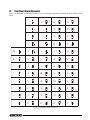
Front Panel Display Characters . . . . . . . . . . . . . . . . . . . . . . . . . . . . . . . . . . . . . . . . . . . . . . . . . . . .
Conversion Factors for Secondary Units . . . . . . . . . . . . . . . . . . . . . . . . . . . . . . . . . . . . . . . . . . . . .
Digital Filtering . . . . . . . . . . . . . . . . . . . . . . . . . . . . . . . . . . . . . . . . . . . . . . . . . . . . . . . . . . . . . . . . .
7.7.1
7.7.2
7.7.3
44
45
47
48
49
DIGFLx Parameters. . . . . . . . . . . . . . . . . . . . . . . . . . . . . . . . . . . . . . . . . . . . . . . . . . . . . . . . . . . . . . . 49
DFSENS and DFTHRH Parameters. . . . . . . . . . . . . . . . . . . . . . . . . . . . . . . . . . . . . . . . . . . . . . . . . . . 49
Setting the Digital Filter Parameters. . . . . . . . . . . . . . . . . . . . . . . . . . . . . . . . . . . . . . . . . . . . . . . . . . . 50
7.8 Analog Output Calibration . . . . . . . . . . . . . . . . . . . . . . . . . . . . . . . . . . . . . . . . . . . . . . . . . . . . . . . .
7.9 Test Mode . . . . . . . . . . . . . . . . . . . . . . . . . . . . . . . . . . . . . . . . . . . . . . . . . . . . . . . . . . . . . . . . . . . .
7.10 Regulatory Mode Functions . . . . . . . . . . . . . . . . . . . . . . . . . . . . . . . . . . . . . . . . . . . . . . . . . . . . . .
7.11 LED Functions . . . . . . . . . . . . . . . . . . . . . . . . . . . . . . . . . . . . . . . . . . . . . . . . . . . . . . . . . . . . . . . .
7.12 Specifications. . . . . . . . . . . . . . . . . . . . . . . . . . . . . . . . . . . . . . . . . . . . . . . . . . . . . . . . . . . . . . . . .
50
51
52
52
53
420 Plus Limited Warranty .................................................................................................................... 54
Rice Lake continually offers web-based video training on a growing selection
of product-related topics at no cost. Visit www.ricelake.com/webinars.
ii
420 Plus Installation Manual
About This Manual
This manual is intended for use by service technicians
responsible for installing and servicing 420 Plus HMI
digital weight indicators. This manual applies to
indicators using Version 1.14 of the 420 Plus software.
Configuration and calibration of the indicator can be
accomplished using the indicator front panel keys, the
EDP command set, or the Revolution® configuration
utility. See Section 3.1 on page 14 for information
about configuration methods.
1.0
This manual can be viewed from the Rice
Lake Weighing Systems distributor site at
www.ricelake.com.
The Operator Card included with this manual
provides basic operating instructions for users of the
420 Plus . Please leave the Operator Card with the
indicator when installation and configuration are
complete.
Introduction
The 420 Plus is a single-channel digital weight
indicator housed in a NEMA 4X/IP66-rated stainless
steel enclosure. The indicator front panel consists of a
large (.8 in, 20 mm), six-digit, seven-segment LED
display and twenty-one-button keypad. Features
include:
• Drives up to eight 350or sixteen 700 load
cells
• Supports 4- and 6-wire load cell connections
• Two configurable digital inputs
• Two configurable digital outputs
• Electronic data processing (EDP) port for full
duplex, RS-232 communications at up to
38400 bps
• Printer port for output-only RS-232 or 20 mA
current loop communications at up to 38400
bps
• Optional analog output module provides 0–10
VDC or 0–20/4–20 mA tracking of gross or
net weight values
• Available in 115 VAC and 230 VAC versions
• Available in DC power version
The 4 2 0 Plu s is NTEP-certified and pending
Measurement Canada approval for Classes III, III HD,
and III L at 10,000 divisions. See Section 7.12 on
page 53 for detailed specifications.
1.1
Warning
Some procedures described in this
manual require work inside the
indicator enclosure. These procedures
are to be performed by qualified
service personnel only.
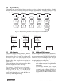
Operating Modes
The 420 Plus has four modes of operation:
Normal (Primary) mode
Normal mode is the “default” mode of the
indicator. The indicator displays gross or net
weights as required, using the LED annunciators
described in Section 1.3 on page 2 to indicate
scale status and the type of weight value
displayed. Once configuration is complete and a
legal seal is affixed to the back of the indicator,
this is the primary mode in which the 420 Plus can
operate.
Piece Count (Secondary) Mode
In piece count mode, the indicator display shows
the number of parts on the scale rather than the
weight of those parts. Piece count mode has two
submodes:
• Count display mode displays the current parts
count and allows ticket printing using the
CFMT print format.
• Sample acquisition mode is used to calibrate
the indicator for parts counting.
Operator access to piece count mode is disabled
when the indicator is shipped from the factory.
Setup mode
Most of the procedures described in this manual
require the indicator to be in setup mode,
including configuration and calibration.
To enter setup mode, remove the large fillister
head screw from the bottom of the enclosure.
Insert a screwdriver or a similar tool into the
access hole and press the setup switch once. The
indicator display changes to show the word
CONFIG.
Test mode
Test mode provides a number of diagnostic
functions for the 420 Plus indicator. Like setup
mode, test mode is entered using the setup switch.
See Section 7.9 on page 51 for more information
about entering and using test mode.
420 Plus Installation Manual - Introduction
1
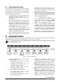
1.2
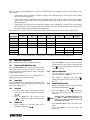
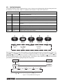
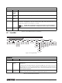
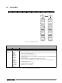
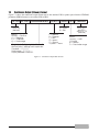
Front Panel Keypad
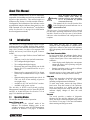
Figure 1-1 shows the 420 Plus LED annunciators, keypad, and normal mode key functions.
The symbols shown above the keys (representing up, down, enter, left, right) describe the key functions assigned
in setup mode. In setup mode, the keys are used to navigate through menus, select digits within numeric values,
and increment/decrement values. See Section 3.1.3 on page 15 for information about using the front panel keys
in setup mode.
Gross
lb
Net
kg
Count
ZERO
POWER
I/O
6
GROSS
NET
TARE
UNITS
MODE
ENTER
SAMPLE
DISPLAY
TARE
SETPOINT
TIME/DATE
2
3
4
5
7
8
9
0
PRINT
CLR
Figure 1-1. 420 Plus Front Panel, Showing LED Annunciators and Normal Mode Key Functions
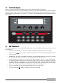
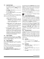
1.3
LED Annunciators
The 420 Plus display uses a set of eight LED annunciators to provide additional information about the value
being displayed:
• Gross and Net annunciators are lit to show whether the displayed weight is a gross or net weight.
Center of zero (
scale is zeroed.
•
•
): Scale is at standstill or within the specified motion band. Some operations, including
Standstill (
tare functions and printing, can only be done when the standstill symbol is shown.
lb and kg annunciators indicate the units associated with the displayed value: lb=pounds, kg=kilograms.
The displayed units can also be set to short tons (tn), metric tons (t), ounces (oz), grams (g), or NONE
(no units information displayed). The lb and kg LEDs function as primary and secondary units
annunciators for some combinations of primary and secondary units. If neither primary nor secondary
units are lb or kg the lb annunciator is lit for primary units, kg for secondary units.
The Count annunciator is lit to show that the indicator is in piece count mode.
•
The Tare Acquired (
•
•
2
): Gross weight is within 0.25 graduations of zero. This annunciator lights when the
•
420 Plus Installation Manual
) lights to show that a tare value was entered.
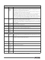
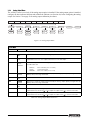
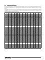
Table 1-1 shows which annunciators are used for all combinations of configured primary and secondary units.
For example:
• If the primary unit is pounds (lb) and the secondary unit is kilograms (kg), the lb LED is lit for primary
units, kg for secondary units.
• If the primary unit is pounds (lb) and the secondary unit is short tons (tn), the lb LED is lit for primary
units, kg for secondary units. There is not an LED for short tons, so the kg LED is used as the secondary
units annunciator.
• If the primary unit is short tons (tn) and the secondary unit is pounds (lb), the lb LED is lit for primary
units (tn), and kg is lit for secondary units (lb). Because there is no LED for short tons, the lb and kg LEDs
are used as primary and secondary units annunciators.
See Section 3.2.2 on page 19 for more information about configuring primary and secondary display units.
Secondary Unit
Primary Unit
lb
kg
oz
g
tn
t
lb
lb / lb
lb / kg
lb / oz
lb / g
lb / kg
kg
kg / lb
kg / kg
kg / oz
kg / g
lb / kg
oz
oz / lb
oz / kg
oz / oz
oz / g
oz / kg
g
g / lb
g / kg
g / oz
g/g
g / kg
tn
lb / kg
lb / kg
lb / oz
lb / g
none
lb / lb
lb / kg
lb / kg
t
lb / kg
lb / lb
lb / kg
none
lb / kg
lb / kg
lb / lb
Table 1-1. Units Annunciators, Showing Primary / Secondary LEDs Used for All Configurations
1.4
Indicator Operations
Basic 420 Plus operations are summarized below.
1.4.1
Toggle Gross/Net Mode/Piece Count
Press the GROSS/NET key to switch the display mode
from gross to net, or from net to gross. If a tare value
has been entered or acquired, the net value is the gross
weight minus the tare.
Gross mode is shown by the Gross annunciator; net
mode is shown by the Net annunciator.
1.4.2
Toggle Units
Press the UNITS key to switch between primary and
secondary units. The appropriate units LED to the
right of the display is lit.
1.4.3
Zero Scale
1. In gross mode, remove all weight from the
scale and wait for the standstill annunciator
).
(
2. Press the ZERO key. The center of zero
(
) annunciator lights to indicate the
scale is zeroed.
1.4.4
Acquire Tare
1. Place container on scale and wait for the
).
standstill annunciator (
2. Press the TARE key to acquire the tare weight
of the container. Net weight is displayed and
the ( ) annunciator lights to show the tare
value was entered
1.4.5
Enter Tare (Keyed Tare)
1. Use the numeric keypad to enter the tare
value, then press the TARE key.
2. Net weight is displayed and the ( )
annunciator lights to show the tare value was
entered.
1.4.6
Remove Stored Tare Value
1. Remove all weight from the scale and wait for
the standstill annunciator (
).
2. Press the TARE key. The ( ) annunciator
goes off, indicating the tare value has been
removed.
Note
Indicators with the REGULA parameter set
to NONE or NTEP (see Section 3.2.5 on
page 23) can clear a stored tare value using
the following procedure:
1. Press DISPLAY TARE to show the stored tare
value.
2. Press the CLEAR key twice to remove the
stored tare.
420 Plus Installation Manual - Introduction
3
1.4.7
Acquire Parts Sample
1. Place empty parts container on scale. Wait for
the standstill annunciator (
), then press
TA R E to acquire the tare weight of the
container.
2. Press MODE (GROSS/NET) key to enter piece
count mode.
Press the CLEAR key to exit.
3. Press the SAMPLE (UNITS) key to enter sample
acquisition mode.
The indicator display shows the message Addnnn ,
where nnn is the sample quantity to be placed on the
scale. You can do one of the following:
•Add the number of parts shown.
•Choose a different sample size. Press the
SAMPLE key to scroll through the
selectable sample quantities (5, 10, 20,
50, 100) or use the numeric keypad to
specify a custom sample size.
•Specify a known piece weight. Press the
SAMPLE key to scroll through the
selectable sample quantities until the PC
WGT prompt is shown. Use the numeric
keypad to enter the piece weight.
4. Once the sample quantity is on the scale,
press ENTER to calibrate the indicator for
counting the new parts. If a sample size was
specified, the indicator display shows the
message –CNT– as it acquires the sample
weight, then switches to count display mode
and shows the part quantity. If a known piece
weight was specified, the display switches to
count display mode immediately.
1.4.8
Display Part Weight
To view gross and net weight parts, press MODE to
switch from count display mode to normal weighing
mode. To view the current piece weight while in count
mode, press DISPLAY TARE key
1.4.9
Display Accumulator
Hold the (MODE) GROSS/NET key for three seconds to
display the accumulated value if enabled in
configuration.
The accumulated value will be displayed for about 10
seconds. To clear the accumulator, press the CLR key
twice while the accumulated value is being displayed.
1.4.10
Display or Change Time
To display the date, press the TIME/DATE key once;
press TIME/DATE a second time to display the time.
4
420 Plus Installation Manual
To set the date, press the TIME/DATE key once. Use the
numeric keypad to enter the date, then press the
ENTER key. Use the numeric keypad to enter the date
in the same format configured for the indicator:
MMDDYY, DDMMYY, or YYMMDD.
To set the time, press the TIME/DATE key twice. Use
the numeric keypad to enter the time in 24-hour
format, then press the ENTER key.
Note
1.4.11
The time and date is backed up with the battery.
If the main power is interrupted, time/date
should not be lost.
Display or Change Setpoint Value
To display a setpoint value, use the numeric keypad to
enter the setpoint number, then press the SETPOINT
key. Or, you can display a setpoint value by pressing
the SETPOINT key a number of times equal to the
setpoint number. For example, to display the value of
setpoint 2, press the SETPOINT key two times.
The current value will display, use the numeric keypad
to enter the new value and press the ENTER key. This
will bring you back to the TRIP submenu. To exit and
save, press the UNITS ( ) and PRINT ( ) keys and
ZERO ( ) and GROSS/NET ( ) to navigate to the
to exit and save. Use
CONFIG menu. Press
Figure 3-11, “Setpoint Menu,” on page 25 to navigate
the menus.
1.4.12
Turn Setpoint On or Off
To turn a setpoint on or off at the front panel, press the
SETPOINT key a number of times equal to the setpoint
number (for example, for setpoint number 2 press the
SETPOINT key two times). Press TARE to exit value
input mode and go left to ENABLE and use the down
arrow key to select On or Off . At this point if the
setpoint is on, you can turn it off by using the right or
left arrow keys.
1.4.13
Print Ticket
1. Wait for standstill annunciator (
).
2. Press the PRINT key to send data to the serial
port.
1.4.14
Enter New ID
1. Ensure digital input 1 or digital input 2 is
configured for NEWID.
2. Activate the digital input.
3. Once activated, the digital input will go into
ID mode.
4. Enter the ID using the numeric keypad and
press TARE.
2.0
Installation
This section describes procedures for connecting load
cells, digital inputs, and serial communications cables
to the 420 Plus indicator. Instructions for field
installation of the analog output option and
replacement of the CPU board are included, along
with assembly drawings and parts lists for the service
technician.
Caution
•
•
•
2.1
Use a wrist strap to ground yourself and protect
components from electrostatic discharge (ESD)
when working inside the indicator enclosure.
This unit uses line fusing which could create an
electric shock hazard. Procedures requiring
work inside the indicator must be performed by
qualified service personnel only.
The supply cord serves as the main power
disconnect for the 420 Plus. The power outlet
supplying the indicator must be installed near
the unit and be easily accessible
Unpacking and Assembly
Immediately after unpacking, visually inspect the 420
Plus to ensure all components are included and
undamaged. The shipping carton should contain the
indicator with attached tilt stand, this manual, and a
parts kit. If any parts were damaged in shipment,
notify Rice Lake Weighing Systems and the shipper
immediately.
The parts kit (PN 85219) contains the items listed
below:
• Two, six-position screw terminals (PN 70599)
for connectors J4 & J1, two, three-position
screw terminals (PN 71125) for connectors J2
and J3, and one, four-position screw terminal
(PN 71126) for connector J6 (see figure 2-4).
• Two 8-32NC x 7/16 fillister head screws (PN
30623).
• Four 8-32NC x 3/8 machine screws (PN
14862) for the indicator backplate (see #1 in
Figure 2-8 12).
• Six neoprene washers (PN 45042) for
backplate screws included in the parts kit.
• Four rubber bumpers (“feet”) for the tilt stand,
(PN 42149).
• Three reducing glands (PN 15664).
• One capacity label (PN 42350).
• Three each of grounding clamps (PN 53075),
external tooth lock washers (PN 15133), and
kep nuts (PN 14626) for cable shield
grounding against the enclosure.
•
•
2.2
One SEC C (section cap) and CLC
(Concentrated Load) (PN 85552) label.
Annunciator labels (PN 85555), replacement
overlay decals for labeling primary and
secondary units LEDs.
Enclosure Disassembly
The indicator enclosure must be opened to connect
cables for load cells, communications, digital inputs,
and analog output.
The 420 Plus has an on/off switch for
the load cells and processor functions.
Before opening the unit, ensure the
power cord is disconnected from the
power outlet. The power outlet must be located near the
indicator to allow the operator to easily disconnect power
to the unit.
Warning
Ensure power to the indicator is disconnected, then
place the indicator face-down on an antistatic work
mat. Remove the screws that hold the backplate to the
enclosure body, then lift the backplate away from the
enclosure and set it aside.
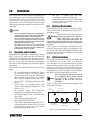
2.3
Cable Connections
The 420 Plus provides four cord grips for cabling into
the indicator: one for the power cord, three to
accommodate load cell, communications, digital
inputs, and analog output cables. Two of the three free
cord grips come with a plug installed to prevent
moisture from entering the enclosure. Depending on
your application, remove the plug from any cord grip
that will be used and install cables as required.
Note
The unit will keep the date and time as long
as it is plugged in, Even if display and load
cells are turned off. When the unit is
unplugged, it will lose date and time
information.
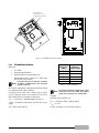
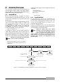
Figure 2-1 shows the recommended assignments for
the 420 Plus cord grips.
Front of
Indicator
Setup Switch
Access Screw
Power Cord
Bottom View
Load Cell Cable
Cord Grip (Open)
Communications Access
Cord Grip (Plugged)
Backplate
Figure 2-1. Recommended Cord Grip Assignments
420 Plus Installation Manual - Installation
5
2.3.1
Cable Grounding
Except for the power cord, all cables routed through
the cord grips should be grounded against the
indicator enclosure. Do the following to ground
shielded cables:
• Use the lockwashers, clamps, and kep nuts
provided in the parts kit to install grounding
clamps on the enclosure studs adjacent to cord
grips. Install grounding clamps only for cord
grips that will be used; do not tighten nuts.
• Route cables through cord grips and
grounding clamps to determine cable lengths
required to reach cable connectors. Mark
cables to remove insulation and shield as
described below:
• For cables with foil shielding, strip insulation
and foil from the cable half an inch (15 mm)
past the grounding clamp (see Figure 2-2).
Fold the foil shield back on the cable where
the cable passes through the clamp. Ensure
silver (conductive) side of foil is turned
outward for contact with the grounding
clamp.
• For cables with braided shielding, strip cable
insulation and braided shield from a point just
past the grounding clamp. Strip another half
inch (15 mm) of insulation only to expose the
braid where the cable passes through the
clamp (see Figure 2-2).
• For load cell cables, cut the shield wire just
past the grounding clamp. Shield wire
function is provided by contact between the
cable shield and the grounding clamp.
• Route stripped cables through cord grips and
clamps. Ensure shields contact grounding
clamps as shown in Figure 2-2. Tighten
grounding clamp nuts.
•
Finish installation using cable mounts and ties
to secure cables inside of indicator enclosure.
/05&*OTUBMMMPDLXBTIFST
mSTUBHBJOTUCBDLQMBUF
VOEFSHSPVOEJOHDMBNQ
$PSEHSJQ
*OTVMBUFEDBCMF
'PJMTJMWFSTJEFPVU
4IJFMEXJSFDVU
#SBJE
$VUJOTVMBUJPOIFSF
GPSCSBJEFEDBCMFT
(SPVOEJOHDMBNQ
$VUJOTVMBUJPOIFSF
GPSGPJMTIJFMEFEDBCMFT
-FOHUIPGGPJMCFGPSFGPMEJOH
CBDLPODBCMFJOTVMBUJPO
Figure 2-2. Grounding Clamp Attachment for Foil-Shielded
and Braided Cabling
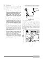
2.3.2
Bypass Power Button
If jumper JMP1 is set for SW position, the power
switch on the front panel of the indicator will turn the
unit ON or OFF. If it is not in the SW position, the
indicator will power up as soon as the AC is applied.
This allows the front panel overlay power control
switch to be bypassed. Label “F” in Figure 2-3 shows
the location of JMP1. Figure 2-4 on page 7 shows
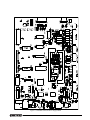
entire board.
Figure 2-3. 420 Plus CPU and Power Supply Board JMP1
Shunt Location
6
420 Plus Installation Manual
Figure 2-4. 420 Plus CPU and Power Supply Board
420 Plus Installation Manual - Installation
7
8JSF"TTFNCMZ
1/
UP+PO
$16#PBSE1/
*/
(/%
$)"
(OE
(OE %$065
Figure 2-5. 420 Plus DC Power Supply
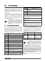
2.3.3
DC Power Wiring Guidelines
Based on:
• 8 x 350
• Analog output installed
• Digital outputs sourcing 20mA each
• Drawing maximum current at 7.5 VDC from
the DC/DC power supply
Note
DC power wiring to the indicator should be
18 AWG to 14 AWG for DC+, DC-, and earth
ground conductors.
In a mobile application, earth ground (chassis) should
be terminated to the vehicle chassis.
In longer power cable runs, voltage drop over the
power conductor needs to be considered. See table
and formula below to compute voltage drop.
VDROP = (2.85A)(x / 1000ft)(length of run in ft.)
2.85A = maximum current draw from DC/DC power
supply
x = Ohms from Table 2-1
8
420 Plus Installation Manual
Wire Gauge
(AWG)
Cable
Impedance
(OHMS/1000ft)
14
2.252
15
3.184
16
4.016
17
5.064
18
6.385
Table 2-1. Cable Impedance
Note
DC voltage supplied to DC/DC power supply
should not be less than 9VDC. Using larger
gauge wire will result in less voltage drop.
Example:
100ft run with 18 AWG wire
VDROP = (2.85A)(6.385 / 1000ft)(100 ft)
VDROP = 1.82V
12VDC will drop to 10.18V after 100ft run.
2.3.4
Load Cells
To attach cable from a load cell or junction box,
remove connector J1 from the board. The connector
plugs into a header on the board as shown in
Figure 2-4 7.
Using one of the 6-position connectors, provided in
the parts kit, wire the load cell cable from the load cell
or junction box to connector J1 on the CPU board (See
Figure 2-4 7). If using six-wire load cell cable (with
sense wires), remove jumpers JP1 and JP2 before
reinstalling connector J1 (see Figure 2-4). For
four-wire installation, leave jumpers JP1 and JP2 on.
When connections are complete, reinstall connector J1
onto the header so that it snaps securely into place.
Use two cable ties to secure the load cell cable to the
inside of the enclosure.
J1 Pin
Function
1
+SIG
2
–SIG
3
+SENSE
4
–SENSE
5
+EXC
6
–EXC
Table 2-2. J1 Pin Assignments
Use grounding procedures described in
Section 2.3.1 on page 6
Note
For 6-wire connections, remove jumpers
JP1 and JP2
For 4-wire connections, leave jumpers JP1
and JP2 on
2.3.5
Serial Communications
Using one of the six-position connectors, provided in
the parts kit, wire the serial communications cables to
J4. Connector J3 provides connections for the EDP/
RS-232 port. Connect communications cables to
connectors J3 and J4 as shown in Table 2-3.
Once cables are attached, reconnect J3 and J4 to the
headers on the board (see Figure 2-4). Use cable ties
to secure serial cables to the inside of the enclosure.
The EDP port supports full duplex RS-232
communications only; the serial port provides either
active 20 mA output or duplex RS-232 transmission.
Both ports are configured using the SERIAL menu.
See Section 3.0 on page 14 for configuration
information.
2.3.7
Analog Output
If the optional analog output module is installed,
attach the output cable to connector J1 on the analog
Port
Connector
Pin
EDP/RS-232
J3
1
TxD
2
RxD
3
Gnd
1
TxD
2
RxD
3
Gnd
4
20mA+
5
20mA–
6
Gnd
Serial Port
J4
Label
Table 2-3. J3 and J4 Pin Assignments
2.3.6
Digital I/O
Digital inputs can be set to provide several indicator
functions, including all keypad functions. The inputs
are active (on) with low voltage (0 VDC) and can be
driven by TTL or 5V logic without additional
hardware. Use the DIG IN menu to configure the
digital inputs. LED’s on the CPU board light when
digital inputs are active.
Digital outputs are typically used to control relays that
drive other equipment. Outputs are designed to sink
not source, switching current. Each output is a
normally open connector circuit, capable of sinking
250 mA when active. Digital outputs are wired to
switch relays when the digital output is active (low, 0
VDC) with reference to 5 VDC supply. LEDs on the
CPU board light when the digital outputs are active.
Port
Connector
Pin
Label
Digital Input
J2
1
DI 1
2
DI 2
3
Gnd
1
Gnd
2
DO 1
3
DO 2
4
+5V
Digital
Output
J6
Table 2-4. J2 and J6 Pin Assignments
output board. Table 2-5 lists the analog output pin
assignments.
420 Plus Installation Manual - Installation
9
Use the ALGOUT menu to configure and calibrate the
analog output module when cabling is complete. See
Section 2.4 for information about installing the analog
output module.
Pin
Signal
1
+ Current Out
2
– Current Out
3
+ Voltage Out
4
– Voltage Out
NTEP - Approval
Fastener
Figure 2-7. NTEP Sealing
Table 2-5. Analog Output Module Pin Assignments
2.4
Analog Output Module Installation
To install or replace the analog output module (PN
85659), follow the steps listed in Section 2.2 on
page 5 for opening the 420 Plus enclosure.
Mount the analog output module on its standoffs in
the location shown in Figure 2-4 7 and plug the
module input into connector J9 on the 420 Plus board.
Connect output cable to the analog output module as
shown in Table 2-5, then reassemble the enclosure
(Section 2.5).
See Figure 7.8 50 for analog output calibration
procedures.
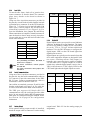
2.5
Enclosure Reassembly
Once cabling is complete, position the backplate over
the enclosure and reinstall the backplate screws. Use
the torque pattern shown in Figure 2-6 to prevent
distorting the backplate gasket. Torque screws to 15
in-lb (1.7 N-m).
10
1
Torque Pattern 3
5
7
6
4
2
Figure 2-6. 420 Plus Enclosure Backplate
10
8
420 Plus Installation Manual
9
2.6
Board Removal
If you must remove the 420 Plus CPU board, use the
following procedure:
1. Disconnect power to the indicator. Remove
backplate as described in Section 2.2 on
page 5.
2. Disconnect power supply cable from
connector J7 on the 420 Plus CPU board.
3. Unplug connectors J1 (load cell cable), J2
(digital inputs), J3 (EDP/RS-232), J4 (serial
communications), J6 (digital outputs), and
J10 & J11 (keypad ribbon cables). If an
analog output board is installed, disconnect
the analog output cable. See Figure 2-4 7 for
connector locations.
4. Remove the five screws from the CPU board,
then lift the board out of the enclosure.
To replace the CPU board, reverse the above
procedure. Be sure to reinstall cable ties to secure all
cables inside the indicator enclosure.
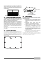
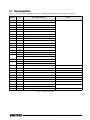
2.7
Replacement Parts
Table 2-6 lists replacement parts for the 420 Plus, including all parts referenced in Figures 2-8 and 2-9.
Ref
Number
PN
1
14862
Screws 8-32NC x 3/8 (8)
2
45042
Sealing washers (8)
3
84387
Backplate (1)
4
84388
backplate gasket (1)
5
14839
Screws 6-32NC x 1/4 (9)
6
85123
CPU and display board assembly (1)
7
84386
Enclosure (1)
8
15144
Nylon washers 1/4x1x1/16 (2)
9
68403
Four-cornered wing knobs for tilt stand (2)
10
29635
Tilt stand (1)
11
44676
Sealing washer (1)
12
42640
Screws 1/4-28NF X 1/4 (2)
13
19538
Cable grip plugs (2)
14
15626
Cable grips (3)
15
30375
Nylon seal rings for cable grips (3)
16
85202
Power cord assembly – 115 VAC
85203
Power cord assembly – 220 VAC
17
84389
Power supply bracket (1)
18
76556
Power supply switch (1)
85554
Power supply, DC/DC converter
20
84397
Overlay panel (1)
21
68216
Rice Lake nameplate (1)
22
85151
Power supply ribbon cable(1)
23
16892
Earth ground label (1)
24
15134
Lock washer, No 8, Type A (3)
25
45043
Ground wire 4 in, No. 8 (1)
27
14626
Kep nuts, 8-32NC Hex (5)
28
15627
Locknuts (3)
30
85494
Protective cover (1)
32
15376
Standoffs, male - female (6)
85791
Fuse, 2.5 Amp 5x20mm
Description (Quantity)
Figure
Figure 2-9 13
Figure 2-8 12
Figure 2-9 13
Table 2-6. Replacement Parts
420 Plus Installation Manual - Installation
11
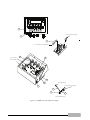
20
From Power Cord (16)
21
22
To J7 header on PC Board (6)
5-pin overlay
28
23
8-pin overlay
24
25
To backplate (3)
From power cord (16)
27
25
27
24
Ground Wire Detail
Figure 2-8. 420 Plus Overlay and Power Supply
12
420 Plus Installation Manual
1
3
2
4
30
32
18
17
5
6
7
16
8
9
15 14 13
12
11
10
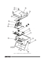
Figure 2-9. 420 Plus Enclosure, Backplate and CPU Board
420 Plus Installation Manual - Installation
13
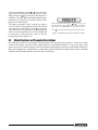
3.0
Configuration
To configure the 420 Plus indicator, the indicator must
be placed in setup mode. The setup switch is accessed
by removing the large fillister head screw on the
enclosure bottom. Switch position is changed by
inserting a screwdriver or similar tool into the access
hole and pressing the setup switch.
When the indicator is placed in setup mode, the word
CONFIG is shown on the display. The CONFIG menu
is the first of ten main menus used to configure the
indicator. Detailed descriptions of these menus are
given in Section 3.2 on page 16. When configuration
is complete, return to the CONFIG menu and press the
(ZERO ) key to exit setup mode, then replace the
setup switch access screw.
3.1
Configuration Methods
The 420 Plus indicator can be configured by using the
front panel keys to navigate through a series of
configuration menus or by sending commands or
configuration data to the EDP port. Configuration
using the menus is described in Section 3.1.3 on
page 15.
Configuration using the EDP port can be
accomplished using either the EDP command set
described in Section 5.0 or the Revolution® software.
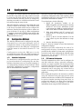
3.1.1
Revolution Configuration
The Revolution configuration utility provides the
preferred method for configuring the 420 Plus
indicator. Revolution runs on a personal computer to
set configuration parameters for the indicator. When
Revolution configuration is complete, configuration
data is downloaded to the indicator.
Figure 3-1. Sample Revolution Configuration Display
14
420 Plus Installation Manual
Revolution supports both uploading and downloading
of indicator configuration data. This capability allows
configuration data to be retrieved from one indicator,
edited, then downloaded to another.
To use Revolution, do the following:
1. Install the Revolution module on an
IBM-compatible personal computer running
Windows ® 98 or later. Minimum system
requirements are 4MB of extended memory
and at least 5MB of available hard disk space.
2. With both indicator and PC powered off,
connect the PC serial port to the indicator
EDP port.
3. Power up the PC and the indicator. Use the
setup switch to place the indicator in setup
mode.
4. Start the Revolution program.
Figure 3-1 shows an example of one of the Revolution
configuration displays.
Revolution provides online help for each of its
configuration displays. Parameter descriptions
provided in this manual for front panel configuration
can also be used when configuring the indicator using
Revolution : the interface is different, but the
parameters set are the same.
3.1.2
EDP Command Configuration
The EDP command set can be used to configure the
420 Plus indicator using a personal computer,
terminal, or remote keyboard. Like Revolution, EDP
command configuration sends commands to the
indicator EDP port; unlike Re vo lu t io n , EDP
commands can be sent using any external device
capable of sending ASCII characters over a serial
connection.
EDP commands duplicate the functions available
using the indicator front panel and provide some
functions not otherwise available. EDP commands can
be used to simulate pressing front panel keys, to
configure the indicator, or to dump lists of parameter
settings. See Section 5.0 on page 33 for more
information about using the EDP command set.
3.1.3
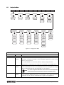
Front Panel Configuration
The 420 Plus indicator can be configured using a series of menus accessed through the indicator front panel when
the indicator is in setup mode. Table 3-1 summarizes the functions of each of the main menus.
Menu
Menu Function
CONFIG
Configuration
Configure grads, zero tracking, zero range, motion band, overload, tare function, sample rate,
and digital filtering parameters.
FORMAT
Format
Set format of primary and secondary units, display rate.
CALIBR
Calibration
Calibrate indicator. See Section 4.0 on page 30 for calibration procedures.
SERIAL
Serial
Configure EDP and printer serial ports.
PROGRM
Program
Set power-up mode, regulatory mode, and consecutive number values.
PFORMT
Print Format
Set print format used for gross and net tickets. See Section 6.0 on page 39 for more
information.
SETPNT
Setpoint
Configure Setpoints and digital outputs.
DIG IN
Digital Input
Assign digital input functions.
ALGOUT
Analog Output
Configure analog output module. Used only if analog output option is installed.
VERS
Version
Display installed software version number.
Table 3-1. 420 Plus Menu Summary
Move UP/
Increrement
VAlue
Move RIGHT/
Next
ENTER value
Move DOWN/
Decrement
Value
Move LEFT/
Previous
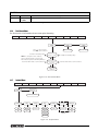
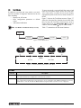
Figure 3-2. Front Panel Key Functions in Setup Mode
Four front panel keys are used as directional keys to navigate through the menus in setup mode (see Figure 3-2).
The UNITS ( ) and PRINT ( ) keys scroll left and right (horizontally) on the same menu level; ZERO ( ) and
GROSS/NET ( ) move up and down (vertically) to different menu levels. The TARE key ( ) serves as an Enter
key for selecting parameter values within the menus. A label above each of these keys identifies the direction
provided by the key when navigating through the setup menus.
1st Level
Parameter
1st Level
Parameter
2nd Level
Parameter
2nd Level
Parameter
Default value
Value
Value
Value
When moving through values below the first menu level, press
to retur n to the level
above. Press
or
to move to the next parameter on the level above
Figure 3-3. Setup Mode Menu Navigation
420 Plus Installation Manual - Configuration
15
To select a parameter, press or to scroll left or
right until the desired menu group appears on the
display, then press to move down to the submenu or
parameter you want. When moving through the menu
parameters, the default or previously selected value
appears first on the display.
To change a parameter value, scroll left or right to
view the values for that parameter. When the desired
value appears on the display, press to select the
value and move back up one level. To edit numerical
values, use the navigation keys to select the digit and
to increment or decrement the value or use the
numeric keypad. (see Figure 3-4).
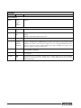
3.2
When editing numeric values, press
or
to change the
digit selected. Press
or
to increment or decrement the
value of the selected digit, or use the numeric keypad.
Press
to save the value entered and return to the level above.
Figure 3-4. Editing Procedure for Numeric Values
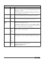
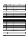
Menu Structures and Parameter Descriptions
The following sections provide graphic representations of the 420 Plus menu structures. In the actual menu
structure, the settings you choose under each parameter are arranged horizontally. To save page space, menu
choices are shown in vertical columns. The factory default setting appears at the top of each column in bold type.
Most menu diagrams are accompanied by a table that describes all parameters and parameter values associated
with that menu. Default parameter values are shown in bold type.
16
420 Plus Installation Manual
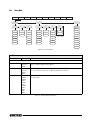
3.2.1
Configuration Menu
CONFIG
FORMAT
XXXXXXX
GRADS
CALIBR
SERIAL
PROGRM
ZTRKBN
ZRANGE
10000
0
number
number
DIGFL1
PFORMT
XXXXXXX
SETPNT
DIG IN
XXXXXXX
ALGOUT
XXXXXXX
VERS
MOTBAN
OVRLOA
SMPRAT
1.900000
1
FS+2%
15HZ
number
number
FS+1D
30HZ
DIGFL2
DIGFL3
FS+9D
60HZ
FS
7.5HZ
DFSENS
DFTHRH
TAREFN
2
2
2
8OUT
NONE
BOTH
4
4
4
16OUT
2DD
NOTARE
8
8
8
32OUT
5DD
PBTARE
16
16
16
64OUT
10DD
KEYED
32
32
32
128OUT
20DD
64
64
64
2OUT
50DD
4OUT
100DD
1
1
1
200DD
250DD
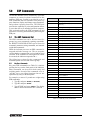
Figure 3-5. Configuration Menu
CONFIG Menu
Parameter
Description
Choices
Level 2 submenus
GRADS
10000
number
Graduations. Specifies the number of full scale graduations. The value entered must be in
the range 1–100 000 and should be consistent with legal requirements and environmental
limits on system resolution.
To calculate GRADS, use the formula, GRADS = Capacity / Display Divisions.
Display divisions for primary and secondary units are specified on the FORMAT menu.
ZTRKBND
0
number
Automatically zeroes the scale when within the range specified, as long as the input is
within the ZRANGE and scale is at standstill. Specify the zero tracking band in ± display
divisions. Maximum legal value varies depending on local regulations.
Note
ZRANGE
1.900000
number
For scales using linear calibration, do not set the zero tracking band to
a value greater than that specified for the first linearization point.
Selects the range within which the scale can be zeroed. The 1.900000 default value is ±
1.9% around the calibrated zero point, for a total range of 3.8%. Indicator must be at
standstill to zero the scale. Use the default value for legal-for-trade applications.
Table 3-2. Configuration Menu Parameters
420 Plus Installation Manual - Configuration
17
CONFIG Menu
Parameter
MOTBAND
Description
Choices
1
number
Sets the level, in display divisions, at which scale motion is detected. If motion is not
detected for 1 second or more, the standstill symbol lights. Some operations, including
print, tare, and zero, require the scale to be at standstill. Maximum legal value varies
depending on local regulations.
If this parameter is set to 0, the standstill annunciator will be set continuously on, and
operations including zero, print, and tare will be performed regardless of scale motion. If 0
is selected, ZTRKBND must also be set to 0.
OVRLOA
FS+2%
FS+1D
FS+9D
FS
Overload. Determines the point at which the display blanks and an out-of-range error
message is displayed. Maximum legal value varies depending on local regulations.
SMPRAT
15HZ
30HZ
60HZ
7.5HZ
Sample rate. Selects measurement rate, in samples per second, of the analog-to-digital
converter. Lower sample rate values provide greater signal noise immunity.
DIGFL1
DIGFL2
DIGFL3
2
4
8
16
32
64
1
Digital filtering. Selects the digital filtering rate used to reduce the effects of mechanical
vibration from the immediate area of the scale.
DFSENS
8OUT
16OUT
32OUT
64OUT
128OUT
2OUT
4OUT
Digital filter cutout sensitivity. Specifies the number of consecutive readings that must fall
outside the filter threshold (DFTHRH parameter) before digital filtering is suspended. If
NONE is selected, the filter is always enabled.
DFTHRH
NONE
2DD
5DD
10DD
20DD
50DD
100DD
200DD
250DD
Digital filter cutout threshold. Specifies the filter threshold, in display divisions. When a
specified number of consecutive scale readings (DFSENS parameter) fall outside of this
threshold, digital filtering is suspended. If NONE is selected, the filter is always enabled.
TAREFN
BOTH
NOTARE
PBTARE
KEYED
Tare function. Enables or disables push-button and keyed tares. Possible values are:
Choices indicate the number of A/D conversions that are averaged to obtain the
displayed reading. A higher number gives a more accurate display by minimizing the
effect of a few noisy readings, but slows down the settling rate of the indicator. See
Section 7.7 on page 49 for more information on digital filtering.
BOTH:Both push-button and keyed tares are enabled
NOTARE:No tare allowed (gross mode only)
PBTARE:Push-button tares enabled
KEYED:Keyed tare enabled
Table 3-2. Configuration Menu Parameters (Continued)
18
420 Plus Installation Manual
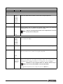
3.2.2
Format Menu
CONFIG
FORMAT
XXXXXXX
CALIBR
SERIAL
PRIMAR
PROGRM
PFORMT
XXXXXXX
SETPNT
DIGIN
XXXXXXX
ALGOUT
XXXXXXX
SECNDR
DECPNT
DSPDIV
888888
1D
888880
2D
8.88888
5D
UNITS
VERS
DSPRAT
DECPNT
DSPDIV
UNITS
MULT
LB
88888.8
5D
KG
0.453592
KG
888888
1D
OZ
number
OZ
888880
2D
TN
88.8888
TN
8.88888
T
888.888
T
88.8888
G
2.5SEC
8888.88
G
888.888
NONE
3SEC
88888.8
NONE
8888.88
LB
4SEC
250MS
500MS
Only used if
UNITS =NONE
750MS
1SEC
1.5SEC
2SEC
6SEC
8SEC
Figure 3-6. Format Menu
FORMAT Menu
Parameter
Choices
Description
Level 2 submenus
PRIMAR
DECPNT
DSPDIV
UNITS
Specifies the decimal position, display divisions, and units used for the primary units. See
Level 3 submenu parameter descriptions.
SECNDR
DECPNT
DSPDIV
UNITS
MULT
Specifies the decimal position, display divisions, units, and conversion multiplier used for
the secondary units. See Level 3 submenu parameter descriptions.
DSPRAT
250MS
500MS
750MS
1SEC
1.5SEC
2SEC
2.5SEC
3SEC
4SEC
6SEC
8SEC
Display rate. Sets the update rate for displayed values. Values are in milliseconds (MS) or
seconds (SEC).
Table 3-3. Format Menu Parameters
420 Plus Installation Manual - Configuration
19
FORMAT Menu
Parameter
Choices
Description
Level 3 submenus
Primary Units (PRIMAR Parameter)
DECPNT
888888
888880
8.88888
88.8888
888.888
8888.88
88888.8
Decimal point location. Specifies the location of the decimal point or dummy zeroes in the
primary unit display. Value should be consistent with local legal requirements.
DSPDIV
1D
2D
5D
Display divisions. Selects the minimum division size for the primary units displayed weight.
UNITS
LB
KG
OZ
TN
T
G
NONE
Specifies primary units for displayed and printed weight. Values are: LB=pound;
KG=kilogram; OZ=ounce; TN=short ton; T=metric ton; G=gram
Note
Indicators sold outside North America are configured with KG for both
primary and secondary units.
Secondary Units (SECNDR Parameter)
DECPNT
88888.8
888888
888880
8.88888
88.8888
888.888
8888.88
Decimal point location. Determines the location of the decimal point or dummy zeros in
the secondary unit display.
DSPDIV
5D
1D
2D
Display divisions. Selects the value of minimum division size of the displayed weight.
UNITS
KG
OZ
TN
T
G
NONE
LB
Specifies secondary units for displayed and printed weight. Values are: KG=kilogram;
OZ=ounce; TN=short ton; T=metric ton; G=gram; LB=pound.
MULT
0.453592
Enter other
choices via
keyboard
Multiplier. Specifies the conversion factor by which the primary units are multiplied to
obtain the secondary units. The default is 0.453592, which is the conversion factor for
changing pounds to kilograms. See Section 7.6 on page 48 for a list of multipliers.
Note
Multipliers are pre-configured within the indicator. Manual entry is
only necessary when NONE is selected under UNITS.
To toggle between primary and secondary units, press the UNITS key.
Table 3-3. Format Menu Parameters (Continued)
20
420 Plus Installation Manual
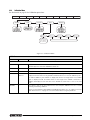
3.2.3
Calibration Menu
See Section 4.0 on page 30 for Calibration procedures.
CONFIG
FORMAT
XXXXXXX
WZERO
CALIBR
WVAL
SERIAL
PROGRM
PFORMT
XXXXXXX
SETPNT
WLIN
WSPAN
WPT–>1
DIGIN
XXXXXXX
ALGOUT
XXXXXXX
VERS
REZERO
WPT–> 2
WPT–> 3
*CAL*
WPT–> 4
WPT–> 5
Same as PT->1
Display and edit
span calibration
A/D count value
Figure 3-7. Calibration Menu
CALIBR Menu
Parameter
Choices
Description
Level 2 submenus
WZERO
—
Display and edit the zero calibration A/D count value.
DO NOT adjust this value after WSPAN has been set!
WVAL
—
Display and edit the test weight value.
WSPAN
—
Display and edit the span calibration A/D count value.
WLIN
WPT->1 —
WPT->5
Press ENTER to display and edit test weight value. Pressing ENTER again will calibrate and
display the raw A/D value. Pressing ENTER a third time will move to the next calibration point.
For millivolt calibration, press ENTER to display and edit the test weight value. Press ENTER
again to display and edit the millivolt value for that weight. Press ENTER a third time to
calibrate and display the raw A/D value. Press ENTER the fourth time to move to the next
point.
REZERO
—
Press Enter to remove an offset value from the zero and span calibrations if hooks or chains
are being used during calibration.
Always use this parameter after WZERO and WSPAN have been set to re-capture a new zero
value. See Section 4.1 on page 30 for more information about using this parameter.
Table 3-4. Calibration Menu Parameters
420 Plus Installation Manual - Configuration
21
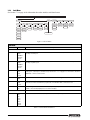
3.2.4
Serial Menu
See Section 7.3 on page 44 for information about the 420 Plus serial data format.
CONFIG
FORMAT
XXXXXXX
CALIBR
SERIAL
PROGRM
PFORMT
XXXXXXX
SETPNT
PRINT
EDP
BAUD
DIGIN
XXXXXXX
S BITS
BITS
TERMIN
EOLDLY
ECHO
ALGOUT
XXXXXXX
STREAM
OFF
EDP
9600
8NONE
1 STOP
CR/LF
000000
ON
PRN
300
7EVEN
2 STOP
CR
number
OFF
BOTH
600
7ODD
VERS
STRRTE
INDUST
LFT
PRNDES
PRNMSG
EDP
OFF
PRN
ON
BOTH
1200
Same as EDP
2400
4800
19200
38400
Figure 3-8. Serial Menu
SERIAL Menu
Parameter
Choices
Description
Level 2 submenus
EDP
BAUD
BITS
TERMIN
EOLDLY
ECHO
Specifies settings for baud rate, data bits, termination characters, end-of-line delay and echo
used by the EDP port.
PRINT
BAUD
BITS
TERMIN
EOLDLY
ECHO
Specifies settings for baud rate, data bits, termination characters, end-of-line delay and echo
used by the printer port.
STREAM
OFF
EDP
PRN
BOTH
Selects the serial port used for continuous transmission. Streaming can be set for the EDP port,
Printer port, or both ports simultaneously. See Section 7.3 on page 44 for information about the
420 Plus continuous data format.
STRRTE
INDUST
LFT
Specifies stream rate. Stream rate can be set to industrial or legal for trade.
PRNDES
EDP
PRN
BOTH
Print destination. Selects the EDP port, printer port, or both ports simultaneously for data
transmission when the PRINT key is pressed or the KPRINT EDP command is sent.
PRNMSG
OFF
ON
Print message. Default will be OFF. When the print key is pressed and data is sent out, the word
PRINT is momentarily displayed on the remote display.
Level 3 Submenus
EDP Port and Printer Port
BAUD
Baud rate. Selects the transmission speed for the EDP or printer port.
9600
300
600
1200
2400
4800
19200
38400
Table 3-5. Serial Menu Parameters
22
420 Plus Installation Manual
SERIAL Menu
Parameter
Choices
Description
BITS
8NONE
7EVEN
7ODD
Selects number of data bits and parity of data transmitted from the EDP or printer port.
S BITS
1 STOP
2 STOP
Stop bits. Sets the number of stop bits to 1 or 2.
TERMIN
CR/LF
CR
Termination character. Selects termination character for data sent from the EDP or printer port.
EOLDLY
000000
number
End-of-line delay. Sets the delay period, in 0.1-second intervals, from when a formatted line is
terminated to the beginning of the next formatted serial output. Value specified must be in the
range 0-255, in tenths of a second (10 = 1 second).
An EOL may be required for continuous transmission at slower baud rates to
ensure the receiving buffer is empty before another string is transmitted
Note
ECHO
This command enables or disables echoing of the serial commands sent to the indicator.
OFF
ON
Table 3-5. Serial Menu Parameters (Continued)
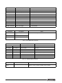
3.2.5
Program Menu
CONFIG
FORMAT
XXXXXXX
CALIBR
SERIAL
PROGRM
PFORMT
XXXXXXX
SETPNT
DIGIN
ALGOUT
PWRUPM
COUNT
REGULA
CONSNU
CONSTU
UID
ACCUM
GO
ACCESS
NTEP
000000
000000
1
ON/OFF
DELAY
SPLISIZ
OIML
number
number
CANADA
NONE
VERS
DATE
ON
ON
TIME
DATFMT
DATSEP
TIMFMT
TIMSEP
MMDDYY
SLASH
24HOUR
COLON
DDMMYY
DASH
12HOUR
COMA
YYMMDD
SEMI
YYDDMM
RTZGRD
0
Figure 3-9. Program Menu
PROGRM Menu
Parameter
Choices
Description
Level 2 submenus
PWRUPM
GO
DELAY
Power up mode. In GO mode, the indicator goes into operation immediately after a brief power
up display test.
In DELAY mode, the indicator performs a power up display test, then enters a 30-second
warm up period. If no motion is detected during the warm-up period, the indicator becomes
operational when the warm up period ends; if motion is detected, the delay timer is reset and
the warm up period repeated.
COUNT
ACCESS
SPLSIZ
Specifies whether operator has access to piece count mode and the default sample size used
for parts counting. See level three submenu for parameter descriptions.
Table 3-6. Program Menu Parameters
420 Plus Installation Manual - Configuration
23
PROGRM Menu
Parameter
REGULA
Choices
NTEP
OIML
CANADA
NONE
Description
Regulatory mode. Specifies the regulatory agency having jurisdiction over the scale site.
OIML, NTEP, and CANADA modes allow a tare to be acquired at any weight greater than zero.
NONE allows tares to be acquired at any weight value.
OIML, NTEP, and CANADA modes allow a tare to be cleared only if the gross weight is at no
load. NONE allows tares to be cleared at any weight value.
NTEP and OIML modes allow a new tare to be acquired even if a tare is already present. In
CANADA mode, the previous tare must be cleared before a new tare can be acquired.
NONE, NTEP and CANADA modes allow the scale to be zeroed in either gross or net mode as
long as the current weight is within the specified ZRANGE. In OIML mode, the scale must be in
gross mode before it can be zeroed; pressing the ZERO key in net mode clears the tare.
CONSNU
000000
number
Consecutive numbering. Allows sequential numbering for print operations. The consecutive
number value is incremented following each print operation.
The initial value of this parameter is set to the start up value specified on the CONSTU
parameter. Changing either CONSTU or CONSNU immediately resets the consecutive number
used for printing.
CONSTU
000000
number
Consecutive number start up value. Specifies the initial consecutive number (CONSNU) value
used when the indicator is powered on.
UID
1
Specifies the unit identification number (any numeric value up to six digits).
ACCUM
ON/OFF
RTZGRD
Turns the accumulator on and off. Stores the count, date and time of last accumulation.
Return to zero grads to re-arm the accumulator. Default = 0.
DATE
DATFMT
DATSEP
Allows selection of date format and date separator. See Level three parameter for descriptions.
TIME
TIMFMT
TIMSEP
Allows selection of time format and separator. See level three parameter for descriptions.
Level 3 submenus
ACCESS
DISABLE
ENABLE
Operator access to piece count mode. Specify DISABLE if piece count mode will not be used.
With access disabled, pressing the GROSS/NET (MODE) key toggles between gross and net
modes only.
SPLSIZ
10
20
50
100
5
PCWGT
Sample size. Specify the default size used for counting scale operations. Sample size can be
changed in counting mode during sample acquisition.
ON/OFF
ON
OFF
Turns the accumulator on and off.
RTZGRD
0
Number
This determines the number of grads away from 0 that it has to return to re-arm the
accumulator between weighments.
DATFMT
MMDDYY
DDMMYY
YYMMDD
Specifies the format used to display or print the date.
DATSEP
SLASH
DASH
SEMI
Specifies the date separator character.
TIMFMT
24HOUR
12HOUR
Specifies the format used to display or print the time.
Table 3-6. Program Menu Parameters (Continued)
24
420 Plus Installation Manual
PROGRM Menu
Parameter
Choices
TIMSEP
Description
COLAN
COMMA
Specifies the time separator character.
Table 3-6. Program Menu Parameters (Continued)
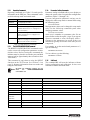
3.2.6
Print Format Menu
See Section 6.0 for information about custom print formatting.
CONFIG
FORMAT
XXXXXXX
CALIBR
SERIAL
PROGRM
PFORMT
XXXXXXX
SETPNT
DIGIN
XXXXXXX
GFMT
Press to insert a space
before the active character
Scroll left in formatting string
NOTE: To change the active character,
use the numeric keypad to enter the new
ASCII value and press the ENTER (TARE) key.
Decrement ASCII value of active character
Display first 6
characters of format
ALGOUT
XXXXXXX
VERS
NFMT
CFMT
Same as GFMT
Same as GFMT
Scroll right in formatting string
Display and edit
active character and
ASCII value
Increment ASCII value of active character
Delete active
character
Figure 3-10. Print Format Menu
3.2.7
Setpoint Menu
CONFIG
FORMAT
XXXXXXX
CALIBR
SETPT1
SERIAL
PROGRM
PFORMT
XXXXXXX
SETPNT
XXXXXXX
DIG IN
XXXXXXX
ALGOUT
XXXXXXX
VERS
SETPT2
Same as SETPT1
ENABLE
KIND
VALUE
TRIP
BNDVAL
HYSTER
ACCESS
OFF
GROSS
number
HIGHER
number
number
OFF
ON
NET
LOWER
ON
If TRIP = HIGHER/
LOWER
INBAND
OUTBAND
Figure 3-11. Setpoint Menu
420 Plus Installation Manual - Configuration
25
SETPNT Menu
Parameter
Choices
Description
Level 2 submenus
SETPT1
SETPT2
ENABLE
KIND
VALUE
TRIP
BNDVAL
Specify settings for setpoint enable, kind, weight value, trip, and band value used by the
setpoint
Level 3 submenus
ENABLE
OFF
ON
Turn setpoint ON or OFF.
KIND
GROSS
NET
Specifies the setpoint kind and determines whether function is based on GROSS or NET
weight.
GROSS or NET setpoint kinds can be used.
VALUE
number
Display and edit the setpoint value
TRIP
HIGHER
LOWER
INBAND
OUTBND
Trips the setpoint when the weight is higher or lower than the setpoint value, or is within or
outside of the band value. LOWER means the output is active until you reach weight. If trip is
HIGHER, the output is active when the setpoint is met or exceeded. INBAND means the
output is active if the weight is within the band value. If trip is OUTBND, the output is active
when the weight is outside of the band value.
BNDVAL
number
The band value for either INBAND or OUTBND trip setpoints. BNDVAL is ignored unless trip is
set to INBAND or OUTBND.
HYSTER
number
Specifies a band around the setpoint value that must be exceeded before the setpoint, once
off, can trip on.
ACCESS
OFF
ON
Front panel access to setpoints. Specify OFF if setpoints will not be used. ON enables
operator to turn setpoints on/off, change value, or change BANDVAL via front panel entry
during weigh mode.
Table 3-7. Setpoint Menu Parameters
26
420 Plus Installation Manual
3.2.8
Digital Input Menu
CONFIG
FORMAT
XXXXXXX
CALIBR
SERIAL
PROGRM
PFORMT
XXXXXXX
SETPNT
DIGIN
XXXXXXX
ALGOUT
XXXXXXX
VERS
DIGIN1
DIGIN2
OFF
OFF
ZERO
ZERO
TARE
TARE
NT/GRS
NT/GRS
UNITS
UNITS
DSPTAR
DSPTAR
PRINT
PRINT
CLRCN
CLRCN
KBDLOC
KBDLOC
HOLD
HOLD
CLRTAR
CLRTAR
CLRACC
CLRACC
ACCUM
ACCUM
NEWID
NEWID
Figure 3-12. Digital Input Menu
DIG IN Menu
Parameter
Choices
Description
Level 2 submenus
DIGIN1
DIGIN2
OFF
ZERO
TARE
NT/GRS
UNITS
DSPTAR
PRINT
CLRCN
KBDLOC
HOLD
CLRTAR
ACCUM
CLRACC
NEWID
Specifies the function activated by digital inputs 1 and 2.
• ZERO, NT/GRS (net/gross mode toggle), TARE, UNITS, and PRINT provide the same
functions as the front panel keys.
• DSPTAR displays the current tare value.
• CLRCN resets the consecutive number to the value specified on the CONSTU parameter
(PROGRM menu).
• KBDLOC disables the keypad while the digital input is held low.
• HOLD holds the current display. Releasing this input clears the running average filter.
• CLRTAR clears the tare.
• ACCUM displays the accumulator.
• CLRACC clears the accumulator.
• NEWID enters the ID number.
Table 3-8. Digital Input Menu Parameters
420 Plus Installation Manual - Configuration
27
3.2.9
Analog Output Menu
The ALGOUT menu is used only if the analog output option is installed. If the analog output option is installed,
configure all other indicator functions and calibrate the indicator (see Section 4.0) before configuring the analog
output. See Section 7.8 on page 50 for analog output calibration procedures.
CONFIG
XXXXXXX
FORMAT
CALIBR
SERIAL
PROGRM
XXXXXXX
PFORMT
SETPNT
OFFSET
ERRACT
MIN
MINNEG
GROSS
0%
FULLSC
000000
NET
20%
HOLD
number
SOURCE
XXXXXXX
DIGIN
XXXXXXX
ALGOUT
VERS
MAX
MAXNEG
OFF
10000
OFF
ON
number
ON
TWZERO
TWSPAN
ZEROSC
Figure 3-13. Analog Output Menu
ALG OUT Menu
Parameter
Choices
Description
Level 2 submenus
SOURCE
GROSS
NET
Specifies the source tracked by the analog output.
OFFSET
0%
20%
Zero offset. Selects whether the analog output supplies voltage (0–10 V) or current (4–20 mA)
output. Select 0% for 0–10 V output; select 20% for 4–20 mA output.
ERRACT
FULLSC
HOLD
ZEROSC
Error action. Specifies how the analog output responds to system error conditions.
Possible values are:
FULLSC
HOLD:
ZEROSC:
Set to full value (10 V or 20 mA)
Hold current value
Set to zero value (0 V or 4 mA)
MIN
000000
number
Specifies the minimum weight value tracked by the analog output. Specify a weight value (in
primary units) in the range 0–999 999.
MINNEG
OFF
ON
Turn ON or OFF.
MAX
010000
number
Specifies the maximum weight value tracked by the analog output. Specify a weight value (in
primary units) in the range 0–999 999.
MAXNEG
OFF
ON
Turn ON or OFF.
TWZERO
—
Tweak zero. Adjust the analog output zero calibration. Use a multimeter to monitor the analog
or
to adjust the output. Press
to save the new value.
output value. Press and hold
TWSPAN
—
Tweak span. Adjust the analog output span calibration. Use a multimeter to monitor the analog
output value. Press and hold
or
to adjust the output. Press
to save the new value.
Table 3-9. Analog Output Menu Parameters
28
420 Plus Installation Manual
3.2.10
Version Menu
The VERS menu is used to check the software version and reg version installed in the indicator. You can also
check the indicator model.
CONFIG
FORMAT
XXXXXXX
CALIBR
SERIAL
PROGRM
PFORMT
XXXXXXX
SETPNT
DIGIN
XXXXXXX
ALGOUT
VERS
Software
version
Figure 3-14. Version Menu
420 Plus Installation Manual - Configuration
29
4.0
Calibration
The 420 Plus can be calibrated using the front panel, EDP commands, or the Revolution® configuration utility.
Each method consists of the following steps:
• Zero calibration
• Span calibration
• Entering the test weight value
• Optional rezero calibration for test weights
using hooks or chains.
The following sections describe the calibration procedure for each of the calibration methods.
CONFIG
WZERO
FORMAT
XXXXXXX
CALIBR
SERIAL
WVAL
PROGRM
PFORMT
XXXXXXX
SETPNT
WLIN
WSPAN
WPT–>1
WPT–> 2
DIGIN
XXXXXXX
ALGOUT
XXXXXXX
VERS
REZERO
WPT–> 3
*CAL*
WPT–> 4
WPT–> 5
Same as PT->1
Display and edit
span calibration
A/D count value
Figure 4-1. Calibration (CALIBR) Menu
4.1
Front Panel Calibration
To calibrate the indicator using the front panel,
1. Place the indicator in setup mode (display
reads CONFIG) and remove all weight from the
scale platform. If your test weights require
hooks or chains, place the hooks or chains on
the scale for zero calibration.
until the display reads CALIBR (see
2. Press
Figure 4-1). Press to go to zero calibration
(WZERO).
3. With WZERO displayed, press
to calibrate
zero. The indicator displays *CAL* while
calibration is in progress. When complete, the
A / D c o u n t f o r t h e z er o c a l i b r a t i o n i s
displayed. DO NOT adjust this value after
WSPAN has been set! Press again to save
the zero calibration value and go to the next
prompt (WVAL).
4. With WVAL displayed, press
to show the
stored calibration weight. Use the procedure
shown in Figure 3-4 14 to enter the actual
value of the test weights to be used for the
span calibration. Press to store the entered
W VA L value and go to span calibration
(WSPAN).
5. With WSPAN displayed, place test weights on
the scale and press to calibrate span. The
30
420 Plus Installation Manual
indicator displays *CAL* while calibration is in
progress. When complete, the A/D count for
the span calibration is displayed. Press
again to store the span calibration value and
go to the next prompt (REZERO).
6. Five-point linearization (using the WLIN
parameter) provides increased scale accuracy
by calibrating the indicator at up to five
additional points between the zero and span
calibrations.
Linearization is optional: if you choose not to
perform linearization, skip the WLIN
parameter; if linearization values have
previously been entered, these values are reset
to zero during calibration. To perform
linearization, follow the procedure below:
Standard Calibration: With WLIN displayed,
to go to the first linearization point
Press
(PT-> 1). Place test weights on the scale and
press or ENTER.
Enter the actual test weight value, then press
to calibrate. The indicator displays *CAL*
while calibration is in progress. When
complete, the A/D count for the linear
calibration is displayed. Press again to save
the calibration value and go to the next
prompt (PT-> 2).
7.
•
•
8.
4.2
Repeat for up to five linearization points. To
exit the linearization parameters, press
to
return to WLIN.
Millivolt Calibration: If millivolt calibration
is enabled press to display and edit the test
weight value, press
again to display and
edit the millivolt value for that weight, press
again to calibrate and display the raw A/D
count, press
again to move to the next
calibration point.
The rezero function is used to remove a
calibration offset when hooks or chains are
used to hang the test weights.
If no other apparatus was used to hang the test
weights during calibration, remove the test
weights and press to return to the CALIBR
menu.
If hooks or chains were used during
calibration, remove these and the test weights
from the scale. With all weight removed,
press to rezero the scale. This function
adjusts the zero and span calibration values.
The indicator displays *CAL* while the zero
and span calibrations are adjusted. When
complete, the adjusted A/D count for the zero
calibration is displayed. Press to save the
value, then press to return to the CALIBR
menu.
Press
until the display reads CONFIG, then
press to exit setup mode.
calibration values. Use the following
commands to set and calibrate a single
linearization point:
WLIN.V1=nnnnn<CR>
WLIN.C1<CR>
The WLIN.V1 command sets the test weight
value (nnnnn) for linearization point 1. The
WLIN.C1 command calibrates the point.
Repeat using the WLIN.Vx and WLIN.Cx
commands as required for additional
linearization points.
6. To remove an offset value, clear all weight
from the scale, including items used to hang
test weights, then send the REZERO EDP
command. The indicator displays *CAL* while
the zero and span calibrations are adjusted.
7. Send the KUPARROW EDP command to exit
setup mode.
4.3
Revolution Calibration
To calibrate the indicator using Revolution , the
indicator EDP port must be connected to a PC running
the Revolution configuration utility.
Use the following procedure to calibrate the indicator:
1. Select Calibration Wizard from the Revolution
tools menu.
2. Revolution uploads calibration data from the
indicator then presents the information in the
calibration wizard, as shown in Figure 4-2
EDP Command Calibration
To calibrate the indicator using EDP commands, the
indicator EDP port must be connected to a terminal or
personal computer. See Section 2.3.5 on page 9 for
EDP port pin assignments; see Section 5.0 on page 33
for more information about using EDP commands.
Once the indicator is connected to the sending device,
1. Place the indicator in setup mode (display
reads CONFIG) and remove all weight from the
scale platform. If your test weights require
hooks or chains, place them on the scale for
zero calibration.
2. Send the WZERO EDP command to calibrate
zero. The indicator displays *CAL* while
calibration is in progress.
3. Place test weights on the scale and use the
WVAL command to enter the test weight
value in the following format:
WVAL=nnnnnn<CR>
4. Send the WSPAN EDP command to calibrate
span. The indicator displays *CAL* while
calibration is in progress.
5. Up to five linearization points can be
calibrated between the zero and span
Figure 4-2. Revolution Calibration Display
3. Enter the Value of Test Weight to be used for
span calibration then click OK.
4. The Zero Calibration dialog box prompts you
to remove all weight from the scale. Clear the
scale and click OK to begin zero calibration.
Note
If your test weights require hooks or
chains, place them on the scale for zero
calibration.
5. When zero calibration is complete, the Span
Calibration dialog box prompts you to place
test weights on the scale for span calibration.
Place tests weights on the scale then click OK.
420 Plus Installation Manual - Calibration
31
6. When span calibration is complete, a dialog
box asks whether you wish to perform linear
calibration. Click Ye s to perform linear
calibration for up to five linearization points, or
click No to complete calibration (see step 8).
7. On the Linear Calibration display, select the
point (1–5) to calibrate, then click Calibrate.
Place test weights on scale then click OK .
When prompted, enter the test weight value
then press Enter. Repeat for additional
linearization points, then click Exit to return to
the Indicator Calibration display.
8. When calibration is complete, the New Settings
fields of the Indicator Calibration display are
filled in. Click Exit to save the new values and
return to the Revolution main menu; to restore
the previous calibration values, click Restore
Settings.
4.4
More About Calibration
The following topics provide additional information
about compensating for environmental factors
(Section 4.4.1) and diagnostic information for
determining expected zero and span coefficients.
4.4.1
Adjusting Final Calibration
Calibration may be affected by environmental factors
including wind, vibration, and angular loading. For
example, if the scale is calibrated with 1000 lb, a
strain test may determine that at 2000 lb the
calibration is 3 lb high. In this case, final calibration
can be adjusted by tweaking WVAL to 998.5 lb. This
adjustment provides a linear correction of 1.5 lb per
1000 lb.
To adjust the final calibration, return to the WVAL
prompt and press to show the test weight value.
Press or to adjust calibration up or down. Press
to save the value, then press
to return to the
CALIBR menu.
4.4.2
Zero Deadload A/D Counts
Table 4-1 lists the ideal A/D counts that result from
input signals of 0–3.0 mV with zero deadload. Actual
values will typically be higher than the values shown
in Table 4-1 but the ideal values can be used when
calibrating the indicator with no attached scale.
Input Signal (mV)
Raw A/D Counts
0.0 mV/V
167,840
0.5 mV/V
335,613
1.0 mV/V
503,377
1.5 mV/V
671,143
2.0 mV/V
838,908
2.5 mV/V
1,100,668
3.0 mV/V
1,174,446
Table 4-1. Ideal A/D Raw Counts
Note
32
420 Plus Installation Manual
When Raw A/D Count is displayed, the six
most significant digits appear. Scroll left or
right to see the full value.
5.0
EDP Commands
The 420 Plus indicator can be controlled by a personal
computer or remote keyboard connected to the
indicator EDP port. Control is provided by a set of
EDP commands that can simulate front panel key
press functions, display and change setup parameters,
and perform reporting functions. The EDP port
provides the capability to print configuration data or
to save that data to an attached personal computer.
This section describes the EDP command set and
procedures for saving and transferring data using the
EDP port.
Command
Function
KZERO
In weighing mode, press the ZERO key
KGROSSNET
In weighing mode, press the GROSS/
NET key
KGROSS
Go to gross mode (pseudo key)
KNET
Go to net mode (pseudo key)
KTARE
Press the TARE key
KUNITS
In weighing mode, press the UNITS key
KPRIM
Go to primary units (pseudo key)
The EDP command set can be divided into five
groups: key press commands, reporting commands,
the RESETCONFIGURATION special function
command, parameter setting commands, and transmit
weight data commands.
When the indicator processes an EDP command, it
responds with the message OK . The OK response
verifies that the command was received and has been
executed. If the command is unrecognized or cannot
be executed, the indicator responds with ??.
The following sections list the commands and
command syntax used for each of these groups.
KSEC
Go to secondary units (pseudo key)
KPRINT
In weighing mode, press the PRINT key
KLEFTARROW
In setup mode, move left in the menu
KRIGHTARROW
In setup mode, move right in the menu
KUPARROW
In setup mode, move up in the menu
KDOWNARROW
In setup mode, move down in the menu
KEXIT
In setup mode, exits to normal mode
KCOUNT
Go to piece count mode (pseudo key)
KTIME
Press the TIME/DATE key once
KDATE
Press the TIME/DATE key twice
KDISPTARE
Press the DISPLAY TARE key
5.1.1
KDISPACCUM
Displays accumulator
KCLRACCUM
Clears accumulator
KCLR
Press the CLEAR key
K0
Press number 0 (zero)
K1
Press number 1
K2
Press number 2
K3
Press number 3
K4
Press number 4
K5
Press number 5
K6
Press number 6
K7
Press number 7
K8
Press number 8
K9
Press number 9
KDOT
Press the decimal point (.)
KENTER
Press the ENTER key
5.1
The EDP Command Set
Key Press Commands
Key press EDP commands (see Table 5-1) simulate
pressing the keys on the front panel of the indicator.
Most commands can be used in both setup and
weighing mode. Several of the commands serve as
“pseudo” keys, providing functions that are not
represented by a key on the front panel.
For example, to enter a 15-pound tare weight using
EDP commands:
1. Type K1 and press ENTER (or RETURN).
2. Type K5 and press ENTER.
3. Type KTARE and press ENTER. The display
shifts to net mode when the tare is entered.
Table 5-1. EDP Key Press Commands
420 Plus Installation Manual - EDP Commands
33
5.1.2
Reporting Commands
5.1.4
Reporting commands (see Table 5-2) send specific
information to the EDP port. These commands can be
used in both setup mode and normal mode.
Command
Function
DUMPALL
List all parameter values
VERSION
Write 420 Plus software version
P
Write current displayed weight with units
identifier. See Section 7.2 on page 43 for
more information.
ZZ
Write current weight and annunciator
status. See Section 7.2 on page 43 for
more information.
S
command<ENTER>
Most parameter values can be changed in setup mode
only. Use the following command syntax when
changing parameter values:
command=value<ENTER>
Write one frame of stream format. See
Table 5-12 on page 37 for information
about the SX and EX commands.
Table 5-2. EDP Reporting Commands
5.1.3
The RESETCONFIGURATION Command
The RESETCONFIGURATION command can be
used to restore all configuration parameters to their
default values. Before issuing this command, the
indicator must be placed in test mode (press and hold
setup switch for approximately three seconds to show
TEST menu).
This command is equivalent to using the DEFLT
function on the TEST menu. See Section 7.9 on
page 51 for more information about test mode and
using the TEST menu.
Note
Parameter Setting Commands
Parameter setting commands allow you to display or
change the current value for a particular configuration
parameter (Tables 5-3 through 5-11).
Current configuration parameter settings can be
displayed in either setup mode or normal mode using
the following syntax:
where value is a number or a parameter value. Use no
spaces before or after the equal (=) sign. If you type an
incorrect command or value, the display reads ?? .
Changes to the parameters are saved as they are
entered but typically do not take effect until you exit
setup mode.
For example, to set the motion band parameter to 5,
type the following:
MOTBAND=5D<ENTER>
To view choices, type the following:
MOTBAND=?<ENTER>
5.1.5
Soft Reset
The command RS will reset the indicator without
losing configuration and calibration. It does reset
consecutive number and count mode.
All load cell calibration settings are lost
when
the
RESETCONFIGURATION
command is run.
Command
Description
Values
GRADS
Graduations
1–100 000
ZTRKBND
Zero track band
OFF, 0.5D, 1D, 3D
ZRANGE
Zero range
1.9%, 100%
MOTBAND
Motion band
1D, 2D, 3D, 5D, 10D, 20D, OFF
OVRLOAD
Overload
FS+2%, FS+1D, FS+9D, FS
SMPRAT
Sample rate
15HZ, 30HZ, 60HZ, 7.5HZ
DIGFLTR1
DIGFLTR2
DIGFLTR3
Digital filtering
1, 2, 4, 8, 16, 32, 64
DFSENS
Digital filter cutout sensitivity
2OUT, 4OUT, 8OUT, 16OUT, 32OUT, 64OUT, 128OUT
DFTHRH
Digital filter cutout threshold
NONE, 2DD, 5DD, 10DD, 20DD, 50DD, 100DD, 200DD, 250DD
TAREFN
Tare function
BOTH, NOTARE, PBTARE, KEYED
Table 5-3. CONFIG EDP Commands
34
420 Plus Installation Manual
Command
Description
Values
PRI.DECPNT
Primary units decimal position
8.88888, 88.8888, 888.888, 8888.88, 88888.8, 888888, 888880
PRI.DSPDIV
Primary units display divisions
1D, 2D, 5D
PRI.UNITS
Primary units
LB, KG, OZ, TN, T, G, NONE
SEC.DECPNT
Secondary units decimal position
8.88888, 88.8888, 888.888, 8888.88, 88888.8, 888888, 888880
SEC.DSPDIV
Secondary units display divisions
1D, 2D, 5D
SEC.UNITS
Secondary units
LB, KG, OZ, TN, T, G, NONE
SEC.MULT
Secondary units multiplier
0.00000–9999.99
DSPRATE
Display rate
250MS, 500MS, 750MS, 1SEC, 1.5SEC, 2SEC, 2.5SEC, 3SEC,
4SEC, 6SEC, 8SEC
Table 5-4. FORMAT EDP Commands
Command
Description
Values
WZERO
Zero calibration
—
WVAL
Test weight value
test_weight_value
WSPAN
Span calibration
—
REZERO
Rezero
—
LC.CD
Set deadload coefficient
value
LC.CW
Set span coefficient
value
Table 5-5. CALIBR EDP Commands
Command
Description
Values
EDP.BAUD
EDP port baud rate
300, 600, 1200, 2400, 4800, 9600, 19200, 38400
EDP.BITS
EDP port data bits/parity
8NONE, 7EVEN, 7ODD
EDP.TERMIN
EDP port termination character
CR/LF, CR
EDP.EOLDLY
EDP port end-of-line delay
0–255 (0.1-second intervals)
EDP.ECHO
EDP port echo
ON, OFF
PRN.BAUD
Printer port baud rate
300, 600, 1200, 2400, 4800, 9600, 19200, 38400
PRN.BITS
Printer port data bits/parity
8NONE, 7EVEN, 7ODD
PRN.TERMIN
Printer port termination character
CR/LF, CR
PRN.EOLDLY
Printer port end-of-line delay
0–255 (0.1-second intervals)
PRN.ECHO
Printer port echo
ON, OFF
STREAM
Streaming port
OFF, EDP, PRN
STRRTE
Stream rate
INDUST, LFT
PRNDEST
Print destination
EDP, PRN
PRNMSG
Print message
OFF, ON
Table 5-6. SERIAL EDP Commands
Command
PWRUPMD
Description
Power up mode
Values
GO, DELAY
Table 5-7. PROGRM EDP Commands
420 Plus Installation Manual - EDP Commands
35
Command
Description
Values
CNTMOD
Counting Mode
ENABLE, DSABLE, SPLSIZ
REGULAT
Regulatory compliance
NTEP, OIML, CANADA, NONE
SPLSIZ
Sample size
10, 20, 50, 100, 5, PCWGT
CONSNUM
Consecutive number
0–999 999
CONSTUP
Consecutive number start-up value 0–999 999
DATEFMT
Date format
MMDDYY, DDMMYY, YYMMDD, YYDDMM
DATESEP
Date separator
SLASH, DASH, SEMI
TIMEFMT
Time format
12HOUR, 24HOUR
TIMESEP
Time separator
COLON, COMMA
ACCUM
Accumulator
ON/OFF
ACCUM. RTZGRADS
Return to zero trigger
0 - 10,000 GRADS
Table 5-7. PROGRM EDP Commands
Command
Description
Values
GFMT
Gross demand print format
string
NFMT
Net demand print format string
CFMT
Count demand print format
string
See Section 6.0 on page 39 for detailed information
Table 5-8. PFORMT EDP Commands
Command
SP1
Description
Values
SP2
SP1.ENABLE
SP2.ENABLE
Setpoint enable
OFF, ON
SP1.KIND
SP2.KIND
Setpoint kind
GROSS, NET
SP1.VALUE
SP2.VALUE
Setpoint value
number
SP1.TRIP
SP2.TRIP
Trip
Higher, Lower, Inband, Outbnd
SP1.BNDVAL
SP2.BNDVAL
Band value
number
SP1.HYSTER
SP2.HYSTER
Hysteresis
number
SP1.ACCESS
SP2.ACCESS
Setpoint access
OFF, ON
Table 5-9. SETPNTS EDP Commands
Command
DIGIN1
DIGIN2
Description
Digital input function
Values
OFF, ZERO, TARE, NT/GRS, UNITS, DSPTAR, PRINT, CLRCN,
KBDLOC, HOLD, CLRTAR, ACCUM, CLRACC, NEWID
Table 5-10. DIG IN EDP Commands
36
420 Plus Installation Manual
Command
Description
Values
SOURCE
Analog output source
GROSS, NET
OFFSET
Zero offset
0%, 20%
ERRACT
Error action
FULLSC, HOLD, ZEROSC
MIN
Minimum value tracked
0–999 999
MINNEG
Minimum negative
OFF, ON
MAX
Maximum value tracked
0–999 999
MAXNEG
Maximum negative
OFF, ON
TWZERO
Zero calibration
0–16 383
TWSPAN
Span calibration
0–16 383
Table 5-11. ALGOUT EDP Commands
5.1.6
Normal Mode Commands
The serial transmit weight data commands (see Table 5-12) transmit data to the EDP port on demand. The SX
and EX commands are valid only in normal operating mode; all other commands are valid in either setup or
normal mode.
Command
Description
Response Format
UID
Set unit ID
nnnnnnn
SD
Set date
MMDDYY, DDMMYY, YYMMDD (enter using DATEFMT
specified)
ST
Set time
hhmm (enter using 24-hour format)
SX
Start EDP streaming
OK or ??
EX
Stop EDP streaming
OK or ??
RS
Reset system
—
nnnnnn UU
where nnnnnn is the weight value, UU is the units.
XA
Transmit accumulator value
XG
Transmit gross weight in displayed units
XN
Transmit net weight in displayed units
XT
Transmit tare weight in displayed units
XG2
Transmit gross weight in non-displayed units
XN2
Transmit net weight in non-displayed units
XT2
Transmit tare weight in non-displayed units
XW
Transmit current piece weight
nnnnnn UU
XC
Transmit current part count
nnnnnn PC
XE
Query system error conditions
nnnnn nnnnn
See Section 7.1.2 on page 43 for detailed information about
the XE command response format.
Table 5-12. Normal Mode Commands
420 Plus Installation Manual - EDP Commands
37
5.2
Saving and Transferring Data
Connecting a personal computer to the 420 Plus EDP
port allows you to save indicator configuration data to
the PC or to download configuration data from the PC
to an indicator. The following sections describe the
procedures for these save and transfer operations.
5.2.1
Saving Indicator Data to a Personal Computer
Configuration data can be saved to a personal
computer connected to the EDP port. The PC must be
running a communications program such as
PROCOMMPLUS®. See Section 2.3.5 on page 9 for
information about serial communications wiring and
EDP port pin assignments.
When configuring the indicator, ensure that the values
set for the BAUD and BITS parameters on the
SERIAL menu match the baud rate, bits, and parity
settings configured for the serial port on the PC. Set
the PRNDEST parameter to EDP.
To save all configuration data, place the indicator in
setup mode and send the DUMPALL EDP command
to the indicator. The 420 Plus responds by sending all
configuration parameters to the PC as
ASCII-formatted text.
38
420 Plus Installation Manual
5.2.2
Downloading Configuration Data from PC to
Indicator
Configuration data saved on a PC or floppy disk can
be downloaded from the PC to an indicator. This
procedure is useful when a number of indicators with
similar configurations are set up or when an indicator
is replaced.
To download configuration data, connect the PC to the
EDP port as described in Section 5.2.1. Place the
indicator in setup mode and use the PC
communications software to send the saved
configuration data to the indicator. When transfer is
complete, calibrate the indicator as described in
Section 4.0.
Calibration settings are included in the
configuration data downloaded to the
indicator. If the receiving indicator is a direct
replacement for another 420 Plus and the
attached scale is not changed, recalibration is not
required.
Note
When downloading configurations that include changed
serial communications settings, edit the data file to place
the serial communications changes at the end of the file.
Communication between the PC and indicator will be lost
once the indicator receives settings for baud rate (BAUD
parameter) or data bits and parity (BITS parameter) that
do not match those configured for the PC.
6.0
Print Formatting
The 420 Plus provides three print formats, GFMT,
NFMT, and CFMT that determine the format of the
printed output when the PRINT key is pressed or when
a KPRINT EDP command is received. If a tare has
been entered or acquired, NFMT is used; otherwise,
GFMT is used.
Each print format can be customized to include up to
300 characters of information, such as company name
and address, on printed tickets. You can use the
indicator front panel (PFORMT menu), EDP
commands, or the Revolution® configuration utility to
customize the print formats.
Note
6.1
Display will only show capital letters, press
the down arrow to view the ASCII character
decimal value on the second menu level.
Refer to Table 7-4 on page 45 and Table 7-5
on page 46 to view the ASCII character
charts.
Print Formatting Commands
Table 6-1 lists commands you can use to format the
gross, net and count print formats. Commands
included in the format strings must be enclosed
between < and > delimiters. Any characters outside of
the delimiters are printed as text on the ticket. Text
characters can include any ASCII character that can
be printed by the output device.
Command
<SU>
Toggle weight data format (formatted/
unformatted)**
<TI>
Time
<DA>
Date
<TD>
Time & Date
Gross, net, and tare weights are 9 digits in length, including
sign (10 digits with decimal point), followed by a space and a
two-digit units identifier. Total field length with units identifier
is 12 (or 13) characters.
ID and consecutive number (CN) fields are 1–6 characters in
length, as required.
* If nn is not specified, 1 is assumed. Value must be in the
range 1–99.
** After receiving an SU command, the indicator sends
unformatted data until the next SU command is received.
Unformatted data omits decimal points, leading and trailing
characters.
Table 6-1. Print Format Commands
The default GFMT, NFMT and CFMT print formats
use only the new line (<NL>) command and the
commands for gross, net, and tare weights in
displayed units (<G>, <N>, and <T>). The default 420
Plus print formats are shown in Table 6-2:
Format
Command
Description
<G>
Gross weight in displayed units
<G2>
Gross weight in non-displayed units
<N>
Net weight in displayed units
<N2>
Net weight in non-displayed units
<T>
Tare weight in displayed units
<T2>
Tare weight in non-displayed units
<A>
Accumulated weight in displayed units
<AC>
Number of accumulator events (5-digit counter)
<AD>
Date of last accumulator event
<AT>
Time of last accumulator event
<UID>
Unit ID number
<CN>
Consecutive number
<NLnn>
New line (nn = number of termination (<CR/LF>
or <CR>) characters)*
<C>
Current piece count
<W>
Current piece weight
<SPnn>
Space (nn = number of spaces)*
Description
Default Format String
Sample Output
GFMT
<G> GROSS<NL>
2046.81 lb GROSS
NFMT
<G> GROSS<NL>
<T> TARE<NL>
<N> NET<NL>
4053.1 lb GROSS
15.6 lb TARE
4037.5 lb NET
CFMT
<C><NL>
512 PC
Table 6-2. GFMT and NFMT Formats
Note
The <G2>, <N2>, and <T2> commands listed
in Table 6-1 print the gross, net, and tare
weights in non-displayed units—that is, in
the units not currently displayed on the
indicator.
ID numbers included in the print format string (<UID>
command) must be set using the UID EDP command.
The 300-character limit of each print format string
includes the output field length of the print formatting
commands, not the command length. For example, if the
indicator is configured to show a decimal point, the <G>
command generates an output field of 13 characters: the
10-character weight value (including decimal point), one
space, and a two-digit units identifier.
PT (preset tare) is added to the tare weight if tare was
keyed in.
Table 6-1. Print Format Commands
420 Plus Installation Manual - Print Formatting
39
6.2
Customizing Print Formats
The following sections describe procedures for
customizing the GFMT, NFMT and CFMT formats
using the EDP port, the front panel (PFORMT menu),
and the Revolution configuration utility.
6.2.1
A ticket printed using this format might look like the
following:
FINE TRANSFER CO
32400 WEST HIGHWAY ROAD
SMALLTOWN
Using the EDP Port
With a personal computer, terminal, or remote
keyboard attached to the 420 Plus EDP port, you can
use the EDP command set to customize the print
format strings.
To view the current setting of a format string, type the
name of the string (GFMT, NFMT or CFMT) and
press ENTER . For example, to check the current
configuration of the GFMT format, type GFMT and
press ENTER. The indicator responds by sending the
current configuration for the gross format:
GFMT=<G> GROSS<NL>
To change the format, use the GFMT, NFMT or
CFMT EDP command followed by an equals sign (=)
and the modified print format string. For example, to
add the name and address of a company to the gross
format, you could send the following EDP command:
Note
Indicator must be placed in the setup mode,
CONFIG is shown on the display.
1345 lb GROSS
6.2.2
Using the Front Panel
If you have no access to equipment for
communication through the EDP port or are working
at a site where such equipment cannot be used, you
can use the PFORMT menu (see Figure 6-1) to
customize the print formats.
Using the PFORMT menu, you can edit the print
format strings by changing the decimal values of the
ASCII characters in the format string.
Lower-case letters and some special
characters cannot be displayed on the 420
Plus front panel (see the ASCII character
charts on page 45 and page 46) and are
shown as blanks. The 420 Plus can send or receive any
ASCII character; the character printed depends on the
particular ASCII character set implemented for the
receiving device.
Note
GFMT=FINE TRANSFER CO<NL>32400 WEST
HIGHWAY ROAD<NL>SMALLTOWN<NL2><G>
GROSS<NL>
CONFIG
FORMAT
XXXXXXX
CALIBR
SERIAL
PROGRM
PFORMT
XXXXXXX
GFMT
Press
to insert a space
before the active character
Scroll left in format string
Decrement ASCII value of active character
SETPNT
DIGIN
XXXXXXX
ALGOUT
XXXXXXX
NFMT
CFMT
Same as GFMT
Same as GFMT
Display first 6
characters of format
Scroll right in format string
Display and edit
active character and
ASCII value
Increment ASCII value of active character
Delete active
character
Figure 6-1. PFORMT Menu, Showing Alphanumeric Character Entry Procedure
40
420 Plus Installation Manual
VERS
6.2.3
Using Revolution
The Revolution configuration utility provides a print formatting grid with a tool bar. The grid allows you to
construct the print format without the formatting commands (<NL> and <SP>) required by the front panel or
EDP command methods. Using Revolution, you can type text directly into the grid, then select weight value
fields from the tool bar and place them where you want them to appear on the printed ticket.
Figure 6-2 shows an example of the Revolution print formatting grid.
Figure 6-2. Revolution Print Format Grid
420 Plus Installation Manual - Print Formatting
41
7.0
7.1
Appendix
Error Messages
The 420 Plus indicator provides a number of error messages. When an error occurs, the message is shown on the
indicator LED display. Error conditions can also be checked remotely by using the XE EDP command as
described in Section 7.1.2 on page 43.
7.1.1
Displayed Error Messages
The 420 Plus provides a number of front panel error messages to assist in problem diagnosis. Table 7-1 lists these
messages and their meanings.
Error Message
Description
Solution
Call Rice Lake Weighing Systems (RLWS) Service.
E A/D
A/D physical error
EEEROM
EEPROM physical error
EVIREE
Virgin EEPROM
EPCKSM
Parameter checksum error
Use TEST menu to perform DEFLT (restore defaults) procedure, then
recalibrate load cells.
EACKSM
A/D calibration checksum error
A/D converter requires recalibration. Call RLWS Service.
EFCKSM
Printer format checksum error
Call RLWS Service.
ELCKSM
Load cell calibration checksum error
Recalibrate load cells.
EIDATA
Internal RAM checksum error
Call RLWS Service.
E REF
A/D reference error
A/D converter requires recalibration. Call RLWS Service.
ERROR
Internal program error
Check configuration. Run XE command (see Section 7.1.2 on
page 43) to determine error type.
Call RLWS Service if unable to clear error by cycling power or if error
recurs.
OVERFL
Overflow error
Weight value too large to be displayed.
------
Gross > overload limit
Gross value exceeds overload limit. Check configuration or signal
input level. Overload can be caused by input signal > 45 mV or
common mode voltage > 950 mV.
______
A/D underrange
A/D reading < –4 mV. Check scale for binding or damage.
RNGERR
GRADS > 100,000
WVAL > 100,000
Only shows up in Config mode.
CNTERR
Count error, insufficient sample size
Reconfigure, parts sample too small for current configuration
EEPERR
EEPROM error
Call Rice Lake Weighing Systems (RLWS) for service
Table 7-1. 420 Plus Error Messages
42
420 Plus Installation Manual
7.1.2
Using the XE EDP Command
The XE EDP command can be used to remotely query
the 420 Plus for the error conditions shown on the
front panel. The XE command returns two 5-digit
numbers in the format:
a decimal representation of any
existing error conditions as described in Table 7-2.
If more than one error condition exists, the number
returned is the sum of the values representing the error
conditions. For example, if the XE command returns
the number 1040, this value represents the sum of an
A/D reference error (1024) and an A/D calibration
checksum error (16).
The second number returned (yyyyy) uses the same bit
assignments as shown in Table 7-2 to indicate whether
the test for the error condition was run. For example,
the value yyyyy = 50815 represents the decimal
equivalent of the binary value 1100 0110 0111 1111.
Using the bit assignments in Table 7-2, this value
indicates all tests were run.
Description
Binary Value
0x0001 EEPROM Error
0000 0000 0000 0001
0x0002 Virgin EEPROM
0000 0000 0000 0010
0x0004 Config Parameter Checksum
0000 0000 0000 0100
0x0008 Load Cell Checksum
0000 0000 0000 1000
0x0010 A/D Calibration Checksum
0000 0000 0001 0000
0x0020 Print Formats Checksum
0000 0000 0010 0000
0x0040 XA Internal RAM Error
0000 0000 0100 0000
0x0080 External RAM Error
0000 0000 1000 0000
0x0100 Reserved
0000 0001 0000 0000
0x0200 ADC Physical Error
0000 0010 0000 0000
0x0400 ADC Reference
0000 0100 0000 0000
0x0800 Count Error
0000 1000 0000 0000
0x1000 Reserved
0001 0000 0000 0000
0x2000 Display Range
0010 0000 0000 0000
0x4000 ADC Range
0100 0000 0000 0000
0x8000 Gross Limit
1000 0000 0000 0000
0x10000 - 0x80000000
Status Messages
Two EDP commands, P and ZZ, can be used to
provide status about the indicator. These commands
are described in the following sections.
7.2.1
xxxxx yyyyy
where xxxxx contains
Error
Code
7.2
Using the P EDP Command
The P EDP command returns the current displayed
weight value to the EDP port, along with the units
identifier. If the indicator is in an underrange or
overload condition, the weight value is replaced with
&&&&&& (overload) or :::::: (underrange).
7.2.2
Using the ZZ EDP Command
The ZZ EDP command can be used to remotely query
which annunciators are currently displayed on the
indicator front panel. The ZZ command returns the
currently displayed weight and a decimal number
representing the LED annunciators currently lit. The
format of the returned data is:
wwwwww uu
zzz
where wwwwww uu is the current displayed weight and
units, z z z is the annunciator status value (see
Table 7-3). If more than one annunciator is lit, the
second number returned is the sum of the values
representing the active annunciators.
Example: If the annunciator status value returned on
the ZZ command is 145, the gross, standstill, and lb
annunciators are lit. 145 represents the sum of the
values for the standstill annunciator (128), gross mode
annunciator (16), and the lb/primary units annunciator
(1).
Decimal
Value
Annunciator
1
lb/primary units
2
kg/secondary units
4
Count
8
Tare entered
16
Gross
32
Net
64
Center of zero
128
Standstill
Table 7-3. Status Codes Returned on the ZZ Command
Reserved
Table 7-2. Error Codes Returned on XE Command
420 Plus Installation Manual - Appendix
43
7.3
Continuous Output (Stream) Format
Figure 7-1 shows the continuous output format sent to the 420 Plus EDP or printer port when the STREAM
parameter (SERIAL menu) is set to either EDP or PRN.
<STX> <POL> <wwwwwww> <UNIT> <G/N> <S> <TERM>
ASCII 02
(decimal)
G = Gross
N = Net
Polarity:
<space> = Positive
<–> = Negative
<^> = Overload
<]> = Underrange
Weight data: 7 digits, right-justified, with
decimal point, l eading zero supression.
Overload = ^^^^^^^
Underrange = ] ] ] ] ] ] ]
Display overflow = OVERFL
L = pounds
K = kilogram
T = ton
G = grams
O = ounces
<space> = none
Figure 7-1. Continuous Output Data Format
44
420 Plus Installation Manual
<CR> <LF>
or <CR>
ASCII 13, 10
(decimal)
Status:
<space> = valid
I = Invalid
M = Motion
O = Over/under range
7.4
ASCII Character Chart
Use the decimal values for ASCII characters listed in Tables 7-4 and 7-5 when specifying print format strings on
the 420 Plus PFORMT menu. The actual character printed depends on the character mapping used by the output
device.
The 420 Plus can send or receive any ASCII character value (decimal 0–255), but the indicator display is limited
to numbers, upper-case, unaccented letters, and a few special characters. See Section 7.5 on page 47 for
information about the 420 Plus LED display.
Control
ASCII
Dec
Hex
ASCII
Dec
Hex
ASCII
Dec
Hex
ASCII
Dec
Hex
Ctrl-@
NUL
00
00
space
32
20
@
64
40
`
96
60
Ctrl-A
SOH
01
01
!
33
21
A
65
41
a
97
61
Ctrl-B
STX
02
02
“
34
22
B
66
42
b
98
62
Ctrl-C
ETX
03
03
#
35
23
C
67
43
c
99
63
Ctrl-D
EOT
04
04
$
36
24
D
68
44
d
100
64
Ctrl-E
ENQ
05
05
%
37
25
E
69
45
e
101
65
Ctrl-F
ACK
06
06
&
38
26
F
70
46
f
102
66
Ctrl-G
BEL
07
07
’
39
27
G
71
47
g
103
67
Ctrl-H
BS
08
08
(
40
28
H
72
48
h
104
68
Ctrl-I
HT
09
09
)
41
29
I
73
49
i
105
69
Ctrl-J
LF
10
0A
*
42
2A
J
74
4A
j
106
6A
Ctrl-K
VT
11
0B
+
43
2B
K
75
4B
k
107
6B
Ctrl-L
FF
12
0C
,
44
2C
L
76
4C
l
108
6C
Ctrl-M
CR
13
0D
-
45
2D
M
77
4D
m
109
6D
Ctrl-N
SO
14
0E
.
46
2E
N
78
4E
n
110
6E
Ctrl-O
SI
15
0F
/
47
2F
O
79
4F
o
111
6F
Ctrl-P
DLE
16
10
0
48
30
P
80
50
p
112
70
Ctrl-Q
DC1
17
11
1
49
31
Q
81
51
q
113
71
Ctrl-R
DC2
18
12
2
50
32
R
82
52
r
114
72
Ctrl-S
DC3
19
13
3
51
33
S
83
53
s
115
73
Ctrl-T
DC4
20
14
4
52
34
T
84
54
t
116
74
Ctrl-U
NAK
21
15
5
53
35
U
85
55
u
117
75
Ctrl-V
SYN
22
16
6
54
36
V
86
56
v
118
76
Ctrl-W
ETB
23
17
7
55
37
W
87
57
w
119
77
Ctrl-X
CAN
24
18
8
56
38
X
88
58
x
120
78
Ctrl-Y
EM
25
19
9
57
39
Y
89
59
y
121
79
Ctrl-Z
SUB
26
1A
:
58
3A
Z
90
5A
z
122
7A
Ctrl-[
ESC
27
1B
;
59
3B
[
91
5B
{
123
7B
Ctrl-\
FS
28
1C
<
60
3C
\
92
5C
|
124
7C
Ctrl-]
GS
29
1D
=
61
3D
]
93
5D
}
125
7D
Ctrl-^
RS
30
1E
>
62
3E
^
94
5E
~
126
7E
Ctrl-_
US
31
1F
?
63
3F
_
95
5F
DEL
127
7F
Table 7-4. ASCII Character Chart (Part 1)
420 Plus Installation Manual - Appendix
45
ASCII
Dec
Hex
ASCII
Dec
Hex
Ç
128
80
ü
129
81
á
160
A0
í
161
A1
é
130
â
131
82
ó
162
A2
83
ú
163
A3
ä
132
à
133
84
ñ
164
85
Ñ
165
ASCII
Dec
Hex
ASCII
192
C0
224
E0
193
C1
ß
225
E1
194
C2
226
E2
195
C3
227
E3
A4
196
C4
228
E4
A5
197
C5
229
E5
Hex
å
134
86
ª
166
A6
198
C6
μ
230
E6
ç
135
87
º
167
A7
199
C7
231
E7
ê
136
88
¿
168
A8
200
C8
232
E8
ë
137
89
169
A9
201
C9
233
E9
è
138
8A
¬
170
AA
202
CA
234
EA
ï
139
8B
1/2
171
AB
203
CB
235
EB
î
140
8C
1/4
172
AC
204
CC
236
EC
ì
141
8D
¡
173
AD
205
CD
237
ED
Ä
142
8E
«
174
AE
206
CE
238
EE
Å
143
8F
»
175
AF
207
CF
239
EF
É
144
90
176
B0
208
D0
240
F0
æ
145
91
177
B1
209
D1
±
241
F1
Æ
146
92
178
B2
210
D2
242
F2
ô
147
93
179
B3
211
D3
243
F3
ö
148
94
180
B4
212
D4
244
F4
ò
149
95
181
B5
213
D5
245
F5
û
150
96
182
B6
214
D6
÷
246
F6
ù
151
97
183
B7
215
D7
˘
247
F7
ÿ
152
98
184
B8
216
D8
°
248
F8
Ö
153
99
185
B9
217
D9
•
249
F9
Ü
154
9A
186
BA
218
DA
250
FA
¢
155
9B
187
BB
219
DB
251
FB
£
156
9C
188
BC
220
DC
¥
157
9D
189
BD
221
DD
Pts
158
9E
190
BE
222
ƒ
159
9F
191
BF
223
Table 7-5. ASCII Character Chart (Part 2)
46
Dec
420 Plus Installation Manual
252
FC
253
FD
DE
254
FE
DF
255
FF
²
7.5
Front Panel Display Characters
Figure 7-2 shows the 7-segment LED character set used to display alphanumeric characters on the 420 Plus front
panel.
-
9
E
Q
:
F
R
/
;
G
S
0
<
H
T
%
1
=
I
U
&
2
>
J
V
3
?
K
W
(
4
@
L
X
)
5
A
M
Y
*
6
B
N
Z
+
7
C
O
[
,
8
D
P
\
.
.
Figure 7-2. 420 Plus Display Characters
420 Plus Installation Manual - Appendix
47
‘
7.6
Conversion Factors for Secondary
Units
The 420 Plus has the capability to mathematically
convert a weight into many different types of units
and instantly display those results with a press of the
UNITS key.
Secondary units can be specified on the FORMAT
menu using the SECNDR parameter, or by using EDP
commands.
Multipliers are preconfigured within the
Note indicator. Manual entry is only necessary
when NONE is selected under UNITS. Long
tons and grain units listed in Table 7-6
cannot be directly specified as primary or secondary
units. For these or other unlisted units of weight, specify
NONE under UNITS.
Primary Unit
grains
ounces
pounds
Ensure that the secondary decimal point position is set
appropriately for the scale capacity in the secondary
units. If the converted value requires more digits than are
available, the indicator will display an overflow message
(OVERFL).
For example, if the primary units are short tons,
secondary units are pounds, and the secondary decimal
point is set to 8888.88, the indicator will overflow if 5 tons
or more are applied to the scale. With 5 tons applied, and
a conversion factor of 2000, the secondary units display
needs five digits to the left of the decimal point to display
the 10000 lb secondary units value.
short tons
grams
kilograms
metric tons
long tons
Note
x Multiplier
Secondary Unit
0.064799
grams
0.002286
ounces
0.000143
pounds
0.000065
kilograms
437.500
grains
28.3495
grams
0.06250
pounds
0.02835
kilograms
7000.00
grains
453.592
grams
16.0000
ounces
0.453592
kilograms
0.000500
short tons
0.000446
long tons
0.000453
metric tons
2000.00
pounds
907.185
kilograms
0.892857
long tons
0.907185
metric tons
15.4324
grains
0.035274
ounces
0.002205
pounds
0.001000
kilograms
15432.4
grains
35.2740
ounces
1000.00
grams
2.20462
pounds
0.001102
short tons
0.000984
long tons
0.001000
metric tons
2204.62
pounds
1000.00
kilograms
1.10231
short tons
0.984207
long tons
2240.00
pounds
1016.05
kilograms
1.12000
short tons
1.01605
metric tons
Multipliers in italics are preconfigured
Table 7-6. Conversion Factors
48
420 Plus Installation Manual
7.7
Digital Filtering
The 420 Plus uses averaged digital filtering to reduce the effect of vibration on weight readings. Adjustable
threshold and sensitivity functions allow quick settling by suspending filter averaging, allowing the weight
reading to jump to the new value. Figure 7-3 shows the digital filter parameters on the CONFIG menu.
DIGFL1
DIGFL2
DIGFL3
DFSENS
DFTHRH
2
2
2
8OUT
NONE
4
4
4
16OUT
2DD
8
8
8
32OUT
5DD
16
16
16
64OUT
10DD
32
32
32
128OUT
20DD
64
64
64
2OUT
50DD
1
1
1
4OUT
100DD
200DD
250DD
Figure 7-3. Digital Filtering Parameters on the Configuration (CONFIG) Menu
DIGFL1= n1
DIGFL2= n2
DIGFL3= n3
n2
n3
A/D Readings
1st Stage
Filter Averages
2nd Stage
Filter Averages
1st Stage
Filter Average
2nd Stage
Filter Average
3rd Stage
Filter Average
n1
Displayed
Value
Figure 7-4. Flow Diagram for 420 Plus Digital Filters
7.7.1
DIGFLx Parameters
The first three digital filtering parameters, DIGFL1,
DIGFL2, and DIGFL3, are configurable filter stages
that control the effect of a single A/D reading on the
displayed weight. The value assigned to each
parameter sets the number of readings received from
the preceding filter stage before averaging (see
Figure 7-4).
The overall filtering effect can be expressed by adding
the values assigned to the three filter stages:
DIGFL1 + DIGFL2 + DIGFL3
For example, if the filters are configured as
DIGFL1=4, DIGFL2=8, DIGFL3=8, the overall
f i l t e r i n g e ff e c t i s 2 0 ( 4 + 8 + 8 ) . Wi t h t h i s
configuration, each A/D reading has a 1-in-20 effect
on the displayed weight value. Setting the filters to 1
effectively disables digital filtering.
7.7.2
DFSENS and DFTHRH Parameters
The three digital filters can be used by themselves to
eliminate vibration effects, but heavy filtering also
increases settling time. The DFSENS (digital filter
sensitivity) and DFTHRH (digital filter threshold)
parameters can be used to temporarily override filter
averaging and improve settling time:
• DFSENS specifies the number of consecutive
scale readings that must fall outside the filter
threshold (DFTHRH) before digital filtering
is suspended.
• DFTHRH sets a threshold value, in display
divisions. When a specified number of
consecutive scale readings (DFSENS) fall
outside of this threshold, digital filtering is
suspended. Set DFTHRH to NONE to turn off
the filter override.
420 Plus Installation Manual - Appendix
49
7.7.3
Setting the Digital Filter Parameters
Fine-tuning the digital filter parameters greatly
improves indicator performance in heavy-vibration
environments. Use the following procedure to
determine vibration effects on the scale and optimize
the digital filtering configuration.
1. In setup mode, set all three digital filters
(DIGFL1, DIGFL2, DIGFL3) to 1. Set
DFTHRH to NONE. Return indicator to
normal mode.
2. Remove all weight from the scale, then watch
the indicator display to determine the
magnitude of vibration effects on the scale.
Record the weight below which all but a few
readings fall. This value is used to calculate
the DFTHRH parameter value in Step 4.
For example, if a heavy-capacity scale
produces vibration-related readings of up to
50 lb, with occasional spikes to 75 lb, record
50 lb as the threshold weight value.
3. Place the indicator in setup mode and set the
digital filters (DIGFLx) to eliminate the
7.8
vibration effects on the scale. (Leave
DFTHRH set to NONE.) Reconfigure as
necessary to find the lowest effective values
for the DIGFLx parameters.
4. With optimum values assigned to the DIGFLx
parameters, calculate the DFTHRH parameter
value by converting the weight value recorded
in Step 2 to display divisions:
threshold_weight_value / DSPDIV
In the example in Step 2, with a threshold
weight value of 50 lb and a display division
value of 5lb: 50 / 5lb = 10DD. DFTHRH
should be set to 10DD for this example.
5. Finally, set the DFSENS parameter high
enough to ignore transient peaks. Longer
transients (typically caused by lower vibration
frequencies) will cause more consecutive
out-of-band readings, so DFSENS should be
set higher to counter low frequency transients.
Reconfigure as necessary to find the lowest
effective value for the DFSENS parameter.
Analog Output Calibration
The following calibration procedure requires a multimeter to measure voltage or current output from the analog
output module. If the option is not already installed, see Section 2.3.7 on page 9.
Note
CONFIG
The analog output must be calibrated after the indicator itself has been configured (Section 3.0) and
calibrated (Section 4.0).
XXXXXXX
FORMAT
CALIBR
SERIAL
PROGRM
XXXXXXX
PFORMT
SETPNT
XXXXXXX
DIGIN
XXXXXXX
ALGOUT
VERS
SOURCE
OFFSET
ERRACT
MIN
MINNEG
MAX
MAXNEG
GROSS
0%
FULLSC
000000
OFF
10000
OFF
NET
20%
HOLD
number
ON
number
ON
TWZERO
ZEROSC
Figure 7-5. Analog Output Menu
1. Enter setup mode and go to the ALGOUT
menu (see Figure 7-5).
• Set OFFSET to 0% for 0–10 V output,
20% for 4–20 mA output
• Set MIN to lowest weight value to be
tracked by the analog output
• Set MAX to highest weight value to be
tracked by the analog output
2. Connect multimeter to analog output:
• For voltage output, connect voltmeter
leads to pins three and four
• For current output, connect ammeter
leads to pins one and two
50
420 Plus Installation Manual
3. Adjust zero calibration: Scroll to the
TWZERO parameter. Check voltage or
current reading on multimeter. Press and hold
or to adjust the zero value up or down.
4. Adjust span calibration: Scroll to the
TWSPAN parameter. Check voltage or
current reading on multimeter. Press and hold
or to adjust the span value up or down.
5. Final zero calibration: Return to the
TWZERO parameter and verify that the zero
calibration has not drifted. Press and hold
or to re-adjust the zero value as required.
6. Return to normal mode. Analog output
function can be verified using test weights.
7.9
Test Mode
In addition to normal and setup modes, test mode
provides a number of diagnostic functions for the 420
Plus, including:
• Display raw A/D count
• Reset configuration parameters to default
values
• A/D internal calibration
Note
Test Mode is intended for factory use only.
To enter test mode, press and hold the setup switch
until the front panel display shows the word TEST.
After about three seconds, the test mode display
automatically shifts to the first test menu function, A/
DTST.
Figure 7-6 shows the Test Menu structure; Figure 7-7
shows the front panel key functions in test mode. Note
that, because the Test Menu functions are all on a
single menu level, the GROSS/NET ( ) key has no
function. Press the ZERO ( ) key to exit test mode.
Table 7-7 summarizes the test menu functions.
TEST
ADOFFS
A/DTST
ADGAIN
DEFLT
Figure 7-6. Test Mode Menu
Move RIGHT
EXIT
ENTER
Not used
Move LEFT
Figure 7-7. Front Panel Key Functions in Test Mode
TEST Menu
Function
Description
A/DTST
Display A/D test
Press and hold Enter key to display raw count from A/D converter.
DEFLT
Default parameters
Press setup switch and Enter key at the same time to reset configuration and calibration parameters to factory
default values. Load cells must be recalibrated before using the indicator (see Section 4.0 on page 30).
Table 7-7. Test Mode Menu Functions
420 Plus Installation Manual - Appendix
51
7.10
Regulatory Mode Functions
Front Panel Key Function
REGULAT
Parameter Value
NTEP
Weight on Scale
zero or negative
positive
CANADA
zero or negative
positive
OIML
zero or negative
positive
NONE
zero or negative
positive
Tare in System
TARE
ZERO
no
no action
ZERO
yes
CLEAR TARE
no
TARE
yes
TARE
no
no action
yes
CLEAR TARE
no
TARE
yes
no action
no
no action
ZERO
yes
CLEAR TARE
ZERO and CLEAR TARE
no
TARE
ZERO
yes
TARE
ZERO and CLEAR TARE
no
TARE
ZERO
yes
CLEAR TARE
no
TARE
yes
CLEAR TARE
TARE
Table 7-8. TARE and ZERO Key Functions for REGULAT Parameter Settings
7.11
LED Functions
Operation Status
The following is a list of diagnostic LEDs for the 420
Plus. see Figure 2-4 7 for locations on the 420 Plus
CPU board.
LEDHB (Microprocessor)
Serial Port Status
LED MEM (Memory Test)
LED1 (EDP Port)
LED2 (PRN Port)
Flashing red = TXD activity
Flashing green = RXD activity
On steady or off = No activity
Flashing red = TXD activity
Flashing green = RXD activity
On steady or off = No activity
Power Supply
LED (+5AV)
LED (+5V & +3.3V)
52
Excitation/ADC supply on
Digital logic supply on
420 Plus Installation Manual
LED AD (ADC)
LED ANA
(Analog Option Card)
Flashing green = Active
Red = Fault
Green = Active
Red = Fault
Green = Pass
Red = Fail
Red = Not Implemented
Digital Input/Output Status
DO 1 (Digital Out 1)
DO2 (Digital Out 2)
DI 1 (Digital In 1)
DI 2 (Digital In 2)
On when lit (active low)
On when lit (active low)
On when lit (active low)
On when lit (active low)
7.12
Specifications
Microcomputer
Model Numbers
United States
International
420-2A (AC) (NEMA 5-15)
420-2C (DC)
420-2B (AC) (CEE-7)
420-2D (DC)
Fusing
115 or 230 VAC
50 or 60 Hz
1.5 A @ 115 VAC (8W)
0.75 A @ 230 VAC (8W)
2.5 A 5 x 20 mm fuse
Power - DC
Line Voltages
Power Consumption
Fusing
Digital Inputs
Digital Outputs
Digital Filters
Phillips PXAG30K main processor @
19.6608 MHz
2 inputs, TTL or switch closure,
active-low
2 outputs, 250 mA Max Sink
3 filters, software selectable
Serial Communications
Power - AC
Line Voltages
Frequency
Power Consumption
Digital Specifications
EDP Port
Printer Port
Full duplex RS-232
fully capable RS-232 or active 20 mA
current loop (transmit only)
38400, 19200, 9600, 4800, 2400,
1200, 600, 300 bps; 7 or 8 data bits;
even, odd, or no parity
Both Ports
Operator Interface
9-36 VDC DC Input
1.5 A Max
Internal short circuit protection
Display
LED annunciators
Analog Specifications
Keypad
Environmental
Operating Temperature –10 to +40°C (legal);
–10 to +50°C (industrial)
Storage Temperature –25 to +70°C
Humidity
0–95% relative humidity
Enclosure
Enclosure Dimensions 9.5 in x 6 in x 3.12 in
24 cm x 15 cm x 8 cm
Weight
2.8 Kg (6.1 lb)
Rating/Material
UL Type 4X
NA
L C ONFE
R
CE
t NA
O
EN
TI
Certifications and Approvals
t
G
S
EI
UR
ES
ON W
Full Scale Input Signal Up to 22.5 mV
Excitation Voltage
+5V single sided
8 x 350 or 16 x 700 load cells
Sense Amplifier
Differential amplifier with
4- and 6-wire sensing
Analog Signal
Input Range
–0.5 mV/V to +4.5 mV/V
Analog Signal
Sensitivity
0.3 V/graduation minimum,
1.5 V/grad recommended
Input Impedance
200 M, typical
Noise (ref to input)
0.3 V p-p with digital filters at 4-4-4
Internal Resolution
8,000,000 counts
Display Resolution
100 000 dd
Measurement Rate
Up to 60 measurements/sec
Input Sensitivity
10 nV per internal count
System Linearity
Within 0.01% of full scale
Zero Stability
150 nV/°C, maximum
Span Stability
3.5 ppm/°C, maximum
Calibration Method
Software, constants stored in
EEPROM
Common Mode
Voltage
–2.35 to +3.45 V, referred to ground
Rejection
130 dB minimum @ 50 or 60 Hz
Normal Mode
Rejection
90 dB minimum @ 50 or 60 Hz
Input Overload
± 12 V continuous, static discharge
protected
RFI Protection
Signal, excitation, and sense lines
protected by capacitor bypass
Analog Output
Optional: fully isolated, voltage or
current output,14-bit resolution.
Voltage output: 0 –10 VDC
Load resistance:1K minimum
Current output: 4–20 mA
External loop resistance: 500
maximum
6-digit LED display. 7-segment, 0.8 in
(20 mm) digits
Gross, net, center of zero, standstill,
lb/primary units, kg/secondary units,
count, tare
21-key flat membrane panel
HT
S AND ME
A
NTEP
CoC Number
Accuracy Class
04-076
III/III L
nmax : 10 000
Measurement Canada (Pending)
Accuracy Class
III/III HD
nmax : 10 000
420 Plus Installation Manual - Appendix
53
420 Plus Limited Warranty
Rice Lake Weighing Systems (RLWS) warrants that all RLWS equipment and systems properly installed by a
Distributor or Original Equipment Manufacturer (OEM) will operate per written specifications as confirmed by
the Distributor/OEM and accepted by RLWS. All systems and components are warranted against defects in
materials and workmanship for two years.
RLWS warrants that the equipment sold hereunder will conform to the current written specifications authorized
by RLWS. RLWS warrants the equipment against faulty workmanship and defective materials. If any equipment
fails to conform to these warranties, RLWS will, at its option, repair or replace such goods returned within the
warranty period subject to the following conditions:
•
•
•
•
•
•
Upon discovery by Buyer of such nonconformity, RLWS will be given prompt written notice with a
detailed explanation of the alleged deficiencies.
Individual electronic components returned to RLWS for warranty purposes must be packaged to
prevent electrostatic discharge (ESD) damage in shipment. Packaging requirements are listed in a
publication, Protecting Your Components From Static Damage in Shipment, available from RLWS
Equipment Return Department.
Examination of such equipment by RLWS confirms that the nonconformity actually exists, and was
not caused by accident, misuse, neglect, alteration, improper installation, improper repair or
improper testing; RLWS shall be the sole judge of all alleged non-conformities.
Such equipment has not been modified, altered, or changed by any person other than RLWS or its
duly authorized repair agents.
RLWS will have a reasonable time to repair or replace the defective equipment. Buyer is responsible
for shipping charges both ways.
In no event will RLWS be responsible for travel time or on-location repairs, including assembly or
disassembly of equipment, nor will RLWS be liable for the cost of any repairs made by others.
THESE
WARRANTIES EXCLUDE ALL OTHER WARRANTIES, EXPRESSED OR IMPLIED, INCLUDING WITHOUT
LIMITATION WARRANTIES OF MERCHANTABILITY OR FITNESS FOR A PARTICULAR PURPOSE . N EITHER
RLWS NOR DISTRIBUTOR WILL, IN ANY EVENT, BE LIABLE FOR INCIDENTAL OR CONSEQUENTIAL DAMAGES.
RLWS
AND BUYER AGREE THAT RLWS’ SOLE AND EXCLUSIVE LIABILITY HEREUNDER IS LIMITED TO
REPAIR OR REPLACEMENT OF SUCH GOODS. IN ACCEPTING THIS WARRANTY, THE BUYER WAIVES ANY AND
ALL OTHER CLAIMS TO WARRANTY.
SHOULD
THE SELLER BE OTHER THAN
WARRANTY CLAIMS.
RLWS,
THE BUYER AGREES TO LOOK ONLY TO THE SELLER FOR
NO TERMS, CONDITIONS, UNDERSTANDING, OR AGREEMENTS PURPORTING TO MODIFY THE TERMS OF THIS
WARRANTY SHALL HAVE ANY LEGAL EFFECT UNLESS MADE IN WRITING AND SIGNED BY A CORPORATE
OFFICER OF RLWS AND THE BUYER.
© 2011 Rice Lake Weighing Systems, Inc. Rice Lake, WI USA. All Rights Reserved.
RICE LAKE WEIGHING SYSTEMS • 230 WEST COLEMAN STREET • RICE LAKE, WISCONSIN 54868 • USA
54
420 Plus Installation Manual
PN 85127 03/11