1
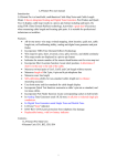
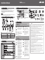
Installation Manual IX-MV (Master Station) Issue Date : Nov. 2014 FK2121 A P1114 SQ 56145 Printed in Thailand Introduction Part Names and Accessories • Read this manual before installation and connection. Read the "Setting Manual" and "Operation Manual" included on the DVD-ROM. • Configure the system settings according to the "Setting Manual" after completing the installation and connection. The system will not function unless it has been properly configured. • After installation, explain to the customer how to use the device, and be sure to provide the accompanying DVD-ROM. Important Color LCD monitor Handset Hook switch Speaker Keypad PC (third party) IX-MV Network Video Recorder (third party) MONITOR button TALK button / Talk indicator (blue) LAN PoE-enabled switch (third party) PoE-enabled switch (third party) IX-DA PoE-enabled switch (third party) PoE-enabled switch (third party) Warning PoE-enabled switch (third party) Dismantling or alteration EMERGENCY IX-DF-HID*1 IX-DF-P*2 IX-DF IX-DF-2RA*1 Number of station registrations in address book Product name IX-MV Master Station IX-DA, IX-DF, IX-DF-HID-I*1, IX-DF-HID*1, Video Door Station IX-DF-2RA*1, IX-DF-PI*2, IX-DF-P*2 IX-BA, IX-SS, IX-SS-2RA*1 Audio Only Door Station *1 North America only. *2 Except North America. HID Card Reader is not included. *3 Only Master Stations can be registered (Max. 20). Number of station registrations in address book 500 stations 20 stations*3 20 stations*3 Refer to the separate "IX-MV Operation Manual" for indicators other than those listed. : Light ON Status (Pattern) Booting 0.75 sec Device error Fast flashing 0.25 sec 0.25 sec Communication failure Long interval flashing 0.5 sec 4 sec Long irregular flashing 1 sec 0.25 sec 0.25 sec 0.25 sec 0.25 sec 1 sec 0.25 sec 0.25 sec Firmware version upgrading Initializing Short irregular flashing Blue light : Light OFF Explanation Status Orange Normal flashing indicator flashing 0.75 sec 0.25 sec 3. Keep the unit away from water or any other liquid. Fire or electric shock could result. 4. The unit is not explosion-proof. Do not install or use near gases or flammable materials. Fire or explosion could result. Caution Indicators Name Negligence could result in death or serious injury. 1. Voltage is applied to parts within the equipment. Do not touch any parts that are not associated with the installation, wiring, or connection. Electric shock could result. 2. Do not dismantle or alter the unit. Fire or electric shock could result. IX-BA Product number * Press and hold the reset button for longer than 1 second, then release to restart station. Quick Start Programming Guide (English) x1 Mounting bracket screw x4 Mounting bracket*1 x1 Wall mounting screws x4 Desk stand screws x4 0.25 sec During communication, Standby (Depends on setting) 5. Do not connect any terminal on the unit to an AC power line. Fire or electric shock could result. 6. Do not put any metal or flammable material into the unit through the openings. Fire, electric shock, or unit trouble could result. 7. Existing wiring such as chime wiring, etc. may contain high voltage AC electricity. Damage to the unit or electric shock could result. Wiring and installation should be done by a qualified technician. Chinese RoHS paper x1 DVD-ROM (Support Tool, Manuals, Custom Sound (sample)) x1 Desk stand x1 Low voltage cable connections CAT5e/6 cable connections Cable tie x1 Precautions IX Support Tool (included with IX-MV) PoE-enabled switch (third party) OFF button Accessories included Installation Manual (this manual) x1 Microphone Door Release button Network Camera (third party) Back MAC address PRIVACY button / Privacy indicator (blue) TRANSFER button / Transfer indicator (orange) LIST button / List indicator (blue) RESET button (beneath the signature plate)* SETTINGS button / Settings indicator (blue) Select button ADJUST button Up/Down and L/R buttons • Perform the installation and connection only after fully understanding this device and the manual. Illustrations used in this manual may be different from the actual ones. Example of System Configuration Status indicator (orange/blue) SPEED DIAL Buttons (x6) Signature plate*1 Signature card*1 x1 x1 *1 Attached to the main unit. Notice 1. Aiphone assumes no responsibility for damages as a result of delayed or unusable services, which were due to failures in network equipment, communication services by Internet and cellular phone companies, line interruptions, communication failures, or inaccuracies or omissions in the transmission unit. 2. We will under no conditions be liable for damage that occurs due to the inability to communicate due to malfunctions, problems, or operational errors in this product. 3. If personal information leaked by eavesdropping or unauthorized access in the communication paths over the Internet, please be aware that Aiphone assumes no responsibility for the damages. 4. We will under no conditions be liable for any damages or losses resulting from this product’s contents or specifications. 5. This manual was created by Aiphone Co., Ltd., all rights reserved. Copying a part of or this entire manual without prior permission from Aiphone Co., Ltd. is strictly forbidden. 6. Please note that this manual may be revised or changed without prior notice. 7. Please note that product specifications may be changed for the sake of improvement without prior notice. 8. Please be aware that it is the customer’s responsibility to ensure that their computer is secure. We will under no conditions be liable for security failures. 9. This system is not intended for life support or crime prevention. It is just a supplementary means of conveying information. Aiphone will under no conditions be liable for loss of life or property which occurs while the system is being operated. 10. Keep the unit more than 1m (3.3’) away from radio or TV set. Negligence could result in injury to people or damage to property. 1. Do not install or make any wire terminations while power supply is plugged in. It can cause electrical shock or damage to the unit. 2. Before turning on power, make sure wires are not crossed or shorted. If not, fire or electric shock could result. 3. Do not install the unit in any of the following locations. Fire, electric shock, or unit trouble could result. • Places under direct sunlight or places near heating equipment that varies in temperature. • Places subject to dust, oil, chemicals, hydrogen sulfide (hot spring). • Places subject to moisture and humidity extremes, such as bathrooms, cellars, greenhouses, etc. • Places where the temperature is quite low, such as inside a refrigerated area or in front of an air conditioner. • Places subject to steam or smoke (near heating or cooking surfaces). • Where noise generating devices such as dimmer switches or inverter electrical appliances are close by. • Locations subject to extremely powerful electric fields. 4. When mounting the unit on a wall, install the unit in a convenient location, but not where it could be jarred or bumped. Injury could result. 5. Do not place or install the unit in the locations subject to frequent vibration or impact. If the unit falls, injury to people or damage to the unit could result. 6. Do not run wires between movable objects (doors, windows, etc.). It may cause malfunction. 7. Do not press on the LCD or subject it to a high impact. The LCD glass could be punctured and result in an injury. 8. If the LCD is punctured, do not allow skin contact with the liquid crystal inside. Inflammation could result. * If liquid crystal is ingested, immediately gargle with water and seek medical attention. * If contact with the eyes or skin occurs, clean with pure water for at least 15 minutes and seek medical attention. 9. Do not put anything on the unit or cover the unit with cloth, etc. Fire or unit trouble could result. 10. Be sure to perform a call test or check the chime volume with the handset on the hook. If you operate the hook switch with the handset on your ear, a sudden call etc. may arrive causing damage to your ear. 11. Install the unit in an area that will be accessible for future inspections, repairs, and maintenance. 12. As to other manufacturer’s devices (such as sensor, detectors, door releases) used with this system, comply with the Specifications and Warranty conditions that the manufacturers or venders present. 13. If the unit is down or does not operate properly, unplug the power supply or turn off the POWER switches. 14. If it is used close to a cellular phone, the unit may malfunction. 15. The unit can be damaged if dropped. Handle with care. 16. The unit turns inoperative during power failure. 17. In areas where broadcasting station antennas are close by, the intercom system may be affected by radio frequency interference. 18. All the units, except for door station, is designed for indoor use only. Do not use outdoor. 19. This product, being a control unit of door release, should not be used as a crime prevention device. 20. It must be noted in advance that the LCD panel, though manufactured with very high precision techniques, inevitably will have a very small portion of its picture elements always lit or not lit at all. This is not considered a unit malfunction. 21. At a gate or porch illuminated by a fluorescent lamp, the picture may vary, but this is not a malfunction. 22. If stripes or fine patterns are reflected, outlines and colors shown may differ from actual people or backgrounds, but this is not a malfunction. 23. Warm-color lighting shining on the video door station may change the tint of the picture on the monitor. 24. When using fluorescent lights to illuminate the screen its colors may periodically change (color rolling), but this is not a malfunction. 25. The unit case may become a warm with use, but this is not a unit malfunction. How to Install How to Connect Connection Precautions Installation of Master Station Wall Mounting <Back wiring> Fill in name on signature card (1) Remove the transparent signature plate while pressing the top or bottom of the plate. *Remove the signature card. (2) Fill in the registered station names onto the white part of the signature card. (3) Reattach the signature plate. Cable 3 The cable is not included with the product. Attach the main unit to the mounting bracket. 3-gang box CAT5e/6 cable Main unit CAT5e/6 cable Mounting height (box center) 1,500 mm (5') Mounting bracket (attached to the back of the main unit.) 1 Low voltage cable Signature card x1 (included*1) Signature plate x1 (included*1) CAT5e/6 cable Radius < 25 mm (1") Pair3 Pair2 Pair3 Pair4 Pair1 Pair2 1 2 3 4 5 6 78 Connect the CAT5e/6 cable and low voltage cable to the main unit, wiring as shown in the figure. Pair1 Pair4 1 2 3 4 5 6 78 T568A <Surface wiring> Example: Back of the IX-MV • Do not peel the jacket off the CAT5e/6 cable any more than is necessary. • Attach the RJ45 modular plugs using either EIA/TIA-568A or 568B. Mounting bracket screws (included) x4 Connect the CAT5e/6 cable and low voltage cable to the main unit. • Insert into the quick connection terminal. • If it is difficult to insert the wire, hold down the disconnect button while inserting the wire. CAT5e/6 cable Radius ≥ 25 mm (1") Attach the mounting bracket to the wall. 2 *1: The signature plate and signature card are attached before shipment. How to attach and remove a low voltage cable • Use a straight cable when connecting between equipment. • Do not use a CAT5e/6 cable with a bending angle of less than a 25 mm (1”) radius. A radius of less than 25 mm (1”) could cause a communication failure. T568B • Use the LAN tester to confirm conduction before connecting the CAT5e/6 cable. • The RJ45 connector with cover cannot be connected to CAT5e/6 cable terminals for Master Station or Door Stations. Use cables without covers on the connectors. Remove button 92 mm (3-5/8") 8 mm(3/8") • Do not pull the CAT5e/6 cable or apply excessive load. Cable precautions 83.5 mm (3-5/16") • Do not use separate conductors, twisted pair cables, or coaxial cables. Mounting height (equipment center) 1,500 mm (5') Mounting bracket Wall mounting screws (included) x4 • Do not use an odd number cable. Point Main unit If mounting on the Desk stand The supplied screws cannot be used on plaster or concrete walls, please use anchors or concrete plugs (both are locally available products). 4 2 Attach the main unit to the mounting bracket. Attach the mounting bracket to the Desk stand. Wiring Connection 1 Assemble the Desk stand. *1 Relay Output Specifications Master Station * Set the Desk stand on a flat surface to keep it stable. If necessary, secure the Desk stand. * The Desk stand can be adjusted in 3 angles. Fit the legs into the grooves of the desired angle. Output method Voltage AC 24V, 0.5A (resistive load) between the DC 24V, 0.5A (resistive load) terminals Minimum load (AC/DC): 100 mV, 0.1 mA CAT5e/6 cable 30° IX-MV Unit LAN/PoE Leg 3 Relay output*1 L Weak current line ϕ0.8mm(20AWG)-2C Mounting bracket Connect the CAT5e/6 cable and low voltage cable to the main unit. Point 100 m (330') L 45° S Desk stand (included) Desk stand screws x4 (included) • Insert the Desk stand screws into the mounting bracket screw holes, then attach the mounting bracket to the Desk stand tightly. • If necessary, secure the CAT5e/6 cable or low voltage cable using the included cable tie. • When using the Desktop mounting, use the included Desk stand. SE 60° *2 Contact Input Specifications 10BASE-T 100BASE-TX CAT5e/6 straight (UTP) PoE-enabled switch ϕ0.8mm(20AWG)-2C Main unit Normally open dry contact Polarized Contact Input*2 Input method Form C dry contact (N/O or N/C) Fixed detection time 200 msec or more Contact resistance Maximum closure resistance: 700 Ω or less Minimum open resistance: 3 kΩ or more Level detection method Terminal 10 mA or less short-circuit current Voltage DC5 V or less between the (between open terminals) terminals