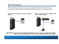
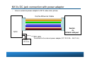
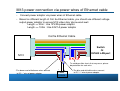
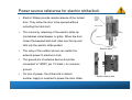
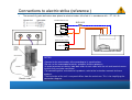
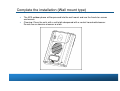
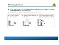
1
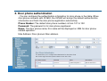
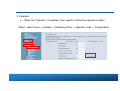
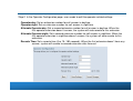
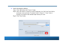
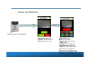
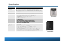
M13 Video Door Phone
User Manual
(Draft)
V0.7
By Kevin Tsou
20140707
M13 IP Video Door Phone Features
M13 Video door phone features
IP addressable video door station
DI / DO dry control for door release
Digital color video camera, NTSC / PAL
Call button, LED indication
Built-in RFID sensor module
Uses 12~24V DC power supply
Door Phone unit
Wall mount
IP addressable
Flush mount
The Front-View of the M13 Video door phone
• The figure below illustrates the front view of the M13. With the point numbers,
you can find its name and a simple description of the part in the following table.
(Wall Mount Type)
(Flush Mount Type)
The Back-View of the M13 Video door phone
(Wall Mount Type)
(Flush Mount Type)
M13 Video Door Phone Hardware Installation
M13 Connection
The M13 video door phone only can be registered via IG7600’s LAN port. Please
connect M13 video door phone to IG7600’s LAN port directly or via a network switch.
• Connect video door phone to IG7600’s LAN port
directly.
• Connect video door phone to IG7600’s LAN
port via network switch.
IMPORTANT: Disconnect the IG7600 (and Network switch ) power when M13 video door
phone is wiring. Keep power off until the wire connection has been made.
Cat.5e Ethernet Cable
Cat.5e Ethernet Cable
Cat. 5e Ethernet cable can be used to connect M13 video door phone and IG7600.
Cat. 5e Ethernet cable resistance - less than 0.094 Ohm/m.
The maximum connection distance cannot exceed 100 meters. When the
distance exceeds 100 meters, an individual switch/hub is needed to connect
M13 video door phone and IG7600.
M13 Connecter
•
14 pin connecter with RJ45 and DC plug (Default)
Color of Wire and Identification
•
•
14 pin connecter without Jack
Twist pair definition:
• Pair1 : Pin1 & Pin 2.
• Pair2 : Pin3 & Pin 4.
• Pair3 : Pin5 & Pin 6.
• Pair4 : Pin7 & Pin 8.
RJ-45 Connector & Cat 5e Ethernet Cable.
• RJ45 jack:
Wiring: CAT5e connect to 14 pin connecter of M13
M13 Power Supply Connection
Please choose from the two following options how to connect M13
to power supply
1. M13’s DC jack connected with power adaptor
In case power supply is available at the spot of M13 installation, please use
the adaptor to connect the door station to power supply.
2. M13 power connected via power wires of Ethernet cable
In case there is no power supply source available at the spot of M13
installation, please use Ethernet cable power wires to connect the door
station to the power adapter as shown on the picture below.
M13’s DC jack connection with power adaptor
•
Use an external power adaptor to M13 video door phone.
Cat 5e Ethernet Cable
Switch
Or
IG7600 LAN port
M13
DC jack
Power
12V-24V
To connect to the external power adaptor (DC 12V/2.0A ~ 24V/1.0A )
M13 power connection via power wires of Ethernet cable
•
Connect power adaptor via power wires of Ethernet cable.
• Based on different length of Cat. 5e Ethernet cable, you should use different voltage
output power adaptor to ensure M13 video door phone work well.
Length <= 30m : Use 12V/2A power adaptor
Length <= 100m : Use 24V/1A power adaptor
Cat 5e Ethernet Cable
Switch
Or
IG7600 LAN port
M13
To avoid possible shorts that may occur, please
do protection for each wire.
•The brown and white/brown wires connect
to DC “-” wire of power adaptor.
-
+
Power
12-24V
•The blue and white/blue wires connect
to DC “+” wire of power adaptor.
Power source reference for electric strike/lock
Electric Strikes provide remote release of the locked
door. They allow the door to be opened without
retracting the latch bolt.
This occurs by releasing of the electric strike lip
(sometimes called keeper or gate). When the door
closes the beveled latch bolt rides over the lip and
falls into the electric strike pocket.
The relay of the outdoor phone can switch the
Electric strike
external power to electronic lock.
The ground pin of external device should be
connected to "GND"( pin 10, black ) for common
ground.
On loss of power, the strike/lock is locked
another supply is required to power the door strike.
Electric mortise lock
Connections to electric strike (reference )
The connectivity point defined on door phone for electronic door strike/lock is in accordance with – PT, AC, EL.
Fail-Secure Door Lock
2KΩ 1/4W
PT
SW1
AC
EL
* When Lock on, SW1 → open
* When Lock open, SW1 → close
External Power supply
+
V=DC +24V
-
R- COM NO
PT
New back panel
With RJ45 connector
& wire set
NOTES
Electric strike
•Connect to the electric door strike according to its specifications.
•Do not use the unoccupied terminals and ports for other purposes.
•In order to prevent miswiring, label both ends of each cable with the unit and terminal names
to which they are to be connected.
•For connecting other manufacturer’s products, refer to the instruction manuals for those
products.
•The illustration of the unit’s rear panel differs from the actual one. This is for simplifying the
connection diagram.
Connections to electric mortis lock (reference )
The connectivity point defined on door phone for electronic door strike/lock is in accordance with – PT, AC, EL.
NOTES
•Connect to the electric door strike according to its specifications.
•Do not use the unoccupied terminals and ports for other purposes.
•In order to prevent miswiring, label both ends of each cable with the unit and terminal names to
which they are to be connected.
•For connecting other manufacturer’s products, refer to the instruction manuals for those products.
•The illustration of the unit’s rear panel differs from the actual one. This is for simplifying the
connection diagram.
Electric mortise lock
Mounting & surface wiring (Wall mount type)
Gecko into the wall, locked the Wall mount frame
Pull the wire from the Wall,
Wire connected with door phone unit
Cable set connected to the back panel of door phone
unit.
Cable set with RJ45
connector & wire set
Complete the installation (Wall mount type)
The M13 outdoor phone will be pressed into the wall mount and use the fixed star screws
and wrench
Cleaning: Clean the units with a soft cloth dampened with a neutral household cleanser.
Do not use an abrasive cleanser or cloth.
M13 Dimension (flush mount type)
Front panel
Side view with back bracket
M13 Assembly (flush mount type)
Back bracket
Main body
Cable set with RJ45
connector & wire set
Face panel
Take off dust cap
Mounting locations
Do not install this unit in any of the following locations where lighting or the ambient environment
could impact the display on the Smartphone.
video monitor due to the characteristics of the door station's camera.
Video Door Phone Setting in IG7600
IG7600 Software version requirement.
- The software version must be V0.5.0.2 or later.
Login IG7600 web page by administrator account.
Level/Rights
Login
Default Password
Administrator
admin1234
adminxxxxxx
Administrator
support
supportxxxxxx
xxxxxx = The last 6 alphanumeric characters of the system’s WAN MAC Address (lower case)
Open Door Allowance & Door phone Authentication
Select Voice -> Phone -> Phone Extension
- This page allows you to configure the two topics for door phone.
Open door allowance
Door phone authentication
1. Open door allowance
- In the phone extension table, select “Yes” by the “Allow Open Door” field to enable
the open door function for the phone number.
2. Door phone authentication
- You can configure the authentication information for door phone in the table. When
door phone connects with IG7600, the IG7600 will assign the default authentication
information and finish the door phone registration automaticity.
Phone Number: The default door phone numbers is from 101 to 102.
Password: The password is for door phone registered.
Name: The door phone name, this name will be displayed on M54 for door phone
related operation.
Mac Address: Door phone’s Mac address.
Door Setting
Select Voice -> Phone -> Door Settings
Door phone number:
– IG7600 supports up to 2 sets of door phone registered. The default door
phone numbers are 101 and 102.
Status:
It indicates door phone status.
– Closed: Door phone is connected.
– Disconnected: Door phone is disconnected.
Night light Start & End time:
– User can configure the night light start and end time.
Open time:
– Configure the outdoor phone relay triggered time. The range is from 500ms
to 10s.
Ring time:
– Configure the ring time.
Talk time:
– Configure the talk time. When it is time out, the system will auto to end the
call.
Speaker & MIC volume:
– Configure the speaker and microphone volume for door phone.
Open door password:
– When the password is set, the password is need for door released by
Smartphone or IP phone.
Answering Position setting:
– IG7600 allows user to set the answer phones. When visitor press door
phone to call-in, the answer phones will ring.
1. Extension:
=> Assign an extension number to answer door phone call-in.
Step 1. Select “extension”
Step 2. Enter an extension number.
2. Operator:
=> When the “Operator” is selected, user needs to define the operator number.
Step1. select Voice -> System -> Numbering Plan -> Operator code -> Configuration.
Step 2. In the Operator Configuration page, user needs to edit the operator-related settings.
Operator day: Set an extension number for call answer in daytime.
Operator night: Set an extension number for call answer in nighttime.
Alternate Operator day: Set a second extension number for call answer in daytime. When the
first operator extension doesn’t answer, the system will auto reroute to this extension.
Alternate Operator night: Set a second extension number for call answer in nighttime. When the
first operator extension in nighttime doesn’t answer, the system will auto reroute to this
extension.
Reroute Time: Set a reroute time (0 or 15~180 seconds). When the first extension doesn’t have any
answer, system will reroute to second extension after time out.
3. UCD Group
=> Select an UCD group, the phones in this UCD group will ring when door phone ringin.
Step 1. Select “UCD Group”.
Step 2. Select one UCD Group from the list.
3.1 Add extension numbers into UCD Group.
Step 1. Select Voice -> System -> Numbering Plan -> Start UCD Group number ->
Configuration.
Step 2. Key in the extension number into “UCD Group Extension”.
Allow Remote IP Phone Open Door (Check box)
– When the check box is checked, system will allow user to open door by
remote IP phone which is registered by IG7600 WAN port.
Door Card
Select Voice -> Phone -> Door Card
- This page provides RFID card settings related operation.
1. Register Card
Step 1: Click the “Start Register” button to begin assay.
Step 2: RFID cards to brush off the lens of door phone
Step 3: When displayed to the card number detection success.
Step 4: Click the “Stop Register” button to end the card detection.
Card Number
displayed when card
detection successes.
2. Card information editing
Step 1: Click “Edit” button from “Card List” table.
Step 2: After “Edit” button is clicked, the card ID displayed in the “Edit Card” field. Edit the
card owner name and status. The default status is “Normal”. If “Lose” status is
selected, user would not be allowed to open door by this card.
Step 3: Click “Save” button.
3. Remove Card
Step 1: Check the “Remove” check box from “Card List”.
Step 2: Click “Delete Selected” button, then this card will be removed
from “Card List”.
M13 Video Door Phone Operation
M13 video door phone registration
Connect M13 video door phone to LAN of IG7600 (or via Ethernet switch), the
IG7600 will finish M13 video door phone registration automatically without any
operation.
Answer video door phone call-in
User can answer the video door phone call-in by IP Phone (M62 or M22) or Smart
phone.
Answer by IP Phone (Voice only)
Visitor ring-in from door phone
Visitor presses calling button.
Pick up the call when phone is ringing.
Answer by Smartphone
Answer
Visitor ring-in from door phone
Visitor presses calling button.
• Open door: open door
• Answer: Answer this call
• Reject: Reject this call
• End: End this call
•Mute: On/Off switch
• Speaker: Speaker/Handset
mode switch
• Keypad: Keypad appeared
• Open door: door released
• Image: Disable/enable video
received. User can stop the
video received to improve voice
quality when voice quality is bad.
•Snapshot: image capturing
Monitor
User can use Smartphone to monitor outdoor phone.
• End: End this call
•Mute: On/Off switch
(Default is Mute On.)
• Speaker: Speaker/Handset
mode switch
• Keypad: Keypad appeared.
• Open door: Open door
• Image: Disable/enable video
received. User can stop the
video received to improve
voice quality when voice
quality is bad.
• Snapshot: image
capturing
• In M54, tap “Function” icon
•Tap “Outdoor phone” icon
• Select the door phone
from list.
Open Door
Open door
There are three ways to open door.
1. Remote door opening using Smartphone
– When Smartphone is in talk/monitor mode with door phone,
tap the “Open door” button.
- The password is needed when user sets password for door opening in
IG7600.
(For password setting please refer to “door setting” section in IG7600 manual. )
Tap “Open door”
Button.
Input password, and then
tap the “OK” button.
2. Remote door opening using IP phone
– When user talks to the door phone using IP phone,
- No password setting
Press Keypad: “#””#”.
- open door with password input
Press keypad: “#” +“password”+ “#”.
3. Use RFID card to open door
(For RFID card registration, please refer to “Outdoor phone card ” section in
IG7600 manual.)
Card reader
location
Tap RFID card to this
area to open door .
M13 IP Video Door Phone Specification
Specification
Processor :
ARM Cortex A8 series
Camera
High Quality CCD camera, Horizontal Resolution: 420 TVL,
Effective Picture Elements: NTSC:510*492, PAL:500*582 (H*V)
Night Light
2 x LED (White)
Features
•
•
•
•
1 * ISO14443 Card Reader, support RFID card
Speaker(8Ω/1W) x1, Microphone(-62±2dB) x1
1 * DI/DO dry control for door release
1 * Ethernet Interface
•
•
•
•
IP connectivity
LED night function, make the image clearly.
Built-in RFID sensor module (MiFare format).
Monitor unit for outdoor image.
Support
protocol
Wall mount
• SIP 2.0 (RFC 3261)/TCP/IP/UDP, RTP, ARP, ICMP, DHCP,
DNS, NTP
• Power supply: External 12V/24V power supply
• Audio codec: G.711 (A/u-law) , G.729
• Audio quality: packet loss concealment, echo suppressor
• Video codec: H.264 baseline real-time video codec
• Automatic firmware and configuration update via TFTP
Flush mount