1
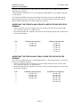
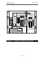
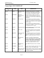
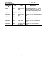
INSTALLATION MANUAL FOR THE
SAMSUNG DCS 70
DIGITAL COMMUNICATIONS SYSTEMS
REV 02
th
SAMSUNG DCS 70
INSTALLATION MANUAL
10 January, 2000
TABLE OF CONTENTS
CHAPTER ONE................................................................................................................... : INTRODUCTION
1-1
CHAPTER TWO........................................................................................................: SITE REQUIREMENTS
2-1
CHAPTER THREE................................................................................... : INSTALLATION OF THE DCS 70
3-1
UNPACKING AND INSPECTION..................................................................................................................... 3-1
KEY SERVICE UNIT INSTALLATION............................................................................................................ 3-1
EXPANSION CABINET INSTALLATION ....................................................................................................... 3-1
PROTECTIVE EARTHING ................................................................................................................................ 3-2
DISTRIBUTION FRAME CABLING................................................................................................................. 3-3
CHAPTER FOUR ...................................................................: INSTALLING CARDS IN THE DCS 70 KSU
4-1
KSU MOTHERBOARD ............................................................................................................................................ 4-1
MEMORY (MEM) CARD ....................................................................................................................................... 4-1
3 TRK CARD (3TRKD70) .................................................................................................................................. 4-2
6 TRK CARD (6TRKD70) .................................................................................................................................. 4-2
4 TRK CARD (4TRK24) ..................................................................................................................................... 4-2
6 TRK CARD (6TRK24) ..................................................................................................................................... 4-2
2 SLI-C CARD ..................................................................................................................................................... 4-3
MISC1&2 CARDS (MISC1D70 / MISC2D70) .................................................................................................. 4-3
MODEM CARD (MODEMD70) ......................................................................................................................... 4-3
8 DLI CARD (8DLID70) ..................................................................................................................................... 4-3
8 SLI CARD (8SLID70)....................................................................................................................................... 4-4
6 MWSLI CARD (6MWSLID70) ........................................................................................................................ 4-4
4BRI CARD (4BRID70) ...................................................................................................................................... 4-4
PRI CARD (DCS CARD) ...................................................................................................................................... 4-5
PLL BOARD (PLLD70)......................................................................................................................................... 4-5
VDIAL CARD (VDIAL-C) (DCS COMPACT CARD) ............................................................................................ 4-5
BSI CARD (DECTBSI-C) (DCS COMPACT CARD) ............................................................................................. 4-5
E&M TIE LINE CARD (EMTIEBDD70) ........................................................................................................... 4-5
LINE REVERSALS, PRS HYBRIDS & TRANSIT CONNECTIONS ............................................................... 4-5
METER PULSE MPD HYBRIDS ....................................................................................................................... 4-6
FITTING MPD & PRS HYBRIDS ...................................................................................................................... 4-6
MODIFYING THE 3TRKD70 AND 6TRKD70 CARDS FOR USE WITH PRS HYBRIDS ............................ 4-7
MODIFYING THE 4TRK24 AND 6TRK24 CARDS FOR USE WITH PRS HYBRIDS.................................. 4-7
NOTE : AUTOGUARD ON THE 3TRK, 4TRK24 & 6TRK(D70&24) CARDS ............................................... 4-8
DCS 70 POWER SUPPLY & FUSING ............................................................................................................... 4-8
POWERING UP THE SYSTEM ......................................................................................................................... 4-8
POWER UP PROBLEMS.................................................................................................................................... 4-9
MEM CARD INDICATIONS.............................................................................................................................. 4-9
DEFAULT TRUNK AND STATION NUMBERING......................................................................................... 4-9
CHAPTER FIVE .............................................................................................. : DCS 70 - SYSTEM CABLING
SAFETY PRECAUTIONS................................................................................................................................... 5-1
SYSTEM CABLING............................................................................................................................................ 5-1
DCS 70 DISTRIBUTION FRAME CIRCUIT ALLOCATION .......................................................................... 5-2
TAIL 1 CIRCUIT ALLOCATION (KSU MOTHERBOARD TAIL). ............................................................ 5-2
Tail 1 - First 25 Pair ......................................................................................................................................... 5-2
Tail 1 - Second 25 Pair..................................................................................................................................... 5-3
i
5-1
th
SAMSUNG DCS 70
INSTALLATION MANUAL
10 January, 2000
3 & 6 TRK CARD CONNECTIONS................................................................................................................... 5-3
8 DLI CARD CONNECTIONS .....................................................................................................................................5-4
8 SLI & 6MWSLI CARD CONNECTIONS .................................................................................................................5-5
BRI ISDN CARD CONNECTIONS..............................................................................................................................5-6
DECT BSI CARD CONNECTIONS .............................................................................................................................5-7
3 & 6 TRK CARD CONNECTIONS................................................................................................................... 5-8
8 DLI CARD CONNECTIONS .....................................................................................................................................5-9
8 SLI & 6MWSLI CARD CONNECTIONS ...............................................................................................................5-10
BRI ISDN CARD CONNECTIONS............................................................................................................................5-11
DECT BSI CARD CONNECTIONS ............................................................................................................. 5-12
CHAPTER SIX................................................. CONNECTING STATION AND OPTIONAL EQUIPMENT
6-1
CONNECTING ANCILLARY EQUIPMENT TO THE SYSTEM..................................................................... 6-1
MUSIC ON HOLD / BACKGROUND MUSIC.............................................................................................. 6-1
EXTERNAL PAGING..................................................................................................................................... 6-2
COMMON BELL ............................................................................................................................................ 6-2
RING OVER PAGE......................................................................................................................................... 6-3
STATION MESSAGE DETAIL RECORDER (SMDR)................................................................................. 6-3
SYSTEM PROGRAMMING FROM A PC (PCMMC)................................................................................... 6-3
REMOTE PROGRAMMING .......................................................................................................................... 6-4
DCS 70 REMOTE PROGRAMMING MODEM CONNECTION:..................................................................................... 6-4
DCS70 Programming Required: ...................................................................................................................... 6-4
Using an external Modem: ............................................................................................................................... 6-4
Set up external modem:.................................................................................................................................... 6-5
REMOTE PROGRAMMING USING INTERNAL OR EXTERNAL MODEM: ..................................................................... 6-5
CHAPTER SEVEN ................................................................: CHANGING SOFTWARE ON THE DCS - 70
7-6
ACCESSING THE EPROMS.......................................................................................................................... 7-6
REPLACING THE EPROMS.......................................................................................................................... 7-6
CHAPTER EIGHT........................................................................................................... : DCS 70 PARTS LIST
ii
8-1
th
SAMSUNG DCS 70
INSTALLATION MANUAL
10 January, 2000
Chapter One : Introduction
This manual describes the procedure to install the Key Service Unit, keysets, single line telephones
and ancillary equipment for the DCS 70 Digital Communication System.
This manual covers the hardware installation and cabling only. The system programming and
configuration is described in the DCS Installation and Maintenance Manual and in the System
Administrators manual.
The operation of the keysets and the single line telephones (SLT’s) is described in the user guides.
The Samsung DCS 70 system should only be installed by fully trained
and qualified personnel.
Page 1-1
th
SAMSUNG DCS 70
INSTALLATION MANUAL
10 January, 2000
Chapter Two : Site Requirements
The installation site for the Samsung DCS 70 System should meet the following requirements • The location for the key service unit (KSU) must provide enough space for easy installation and
have adequate lighting. The Key Service Unit measures 57cm high by 36cm wide by 13cm deep.
• Select a location that will minimize cable lengths. See the maximum cable length limits in Chapter
6.
• The equipment should not be exposed to moisture, direct sunlight, corrosive fumes, dust, constant
vibration or strong magnetic fields such as those generated by motors and copy machines.
• A single phase, correctly earthed, 240V, 10Amp, 50Hz, AC General Purpose Outlet (GPO) must
be provided within two metres of the KSU. The GPO must be easily accessible and kept clear of
obstructions. Extension cords must not be used. A dedicated, separately fused circuit should be
used to minimize the risk of other electrical equipment being connected that could adversely affect
system operation.
• Ensure that all wires and cable going to and coming from the KSU are properly routed. The cables
should not cross fluorescent lights or run parallel with AC wires.
• The equipment must be located in an environment that will remain within the Temperature range
of 0oC to 45oC and 10% to 95% Relative Humidity, non-condensing.
• Allow at least 30cm clearance on both sides and 30cm clearance on top of the KSU to ensure
proper ventilation. Refer to Figure 2.1
• Do not install the KSU in close proximity to a fire sprinkler head or other sources of water.
Meeting these requirements will help to ensure proper performance and greater life expectancy of the
system.
Immunity to Interference.
The DCS 70 System has been designed to be immune to the levels
of interference normally found within residential and commercial
premises (for example, mains dips and breaks, electro-static
discharge, overvoltages and transients, electromagnetic fields).
It is the customer’s responsibility to provide an environment for the DCS 70 system, Keysets and
cabling that does not contain excessive sources of interference that could affect the operation of the
systems.
Page 2-1
th
SAMSUNG DCS 70
INSTALLATION MANUAL
10 January, 2000
Min 300
mm
Min 300
mm
Min 300
mm
Max 1800 mm
Min 380
mm
Figure 2-1. Wall Mounting the KSU
Page 2-2
th
SAMSUNG DCS 70
INSTALLATION MANUAL
10 January, 2000
Chapter Three : Installation Of The DCS 70
UNPACKING AND INSPECTION
After unpacking the KSU, inspect the unit for signs of physical damage. KSUs with any sign
of physical damage should be returned to the supplier for replacement.
Check to see that the KSU carton includes the following items:
• DCS 70 Key Service Unit (KSU) which includes:
• Memory card
• 20W Ringer
• Paper Mounting Template
• Power cable
• Wall-mount kit consisting of cable ties, four screws, spare fuses and Battery Backup cable
The EXPANSION Cabinet is provided as an add-on option. If provided, check that the
expansion cabinet carton includes the following:
• Expansion Cabinet
• Mounting screws and cable tie.
KEY SERVICE UNIT INSTALLATION
The Key Service Unit (KSU) must be wall-mounted in a vertical position.
The KSU has 4 key holes on the sides of the KSU for wall mounting. See Figure 3.1
Use the mounting template supplied to position the screw holes correctly. Insert the screws
but do not tighten.
Position the KSU on to all screws at the same time and then lower the KSU so that it is
secured in the Keyholes. Tighten all screws to complete the installation.
(see Figure 3-1).
The KSU should be mounted on a section of the wall capable of holding the weight of the
system (approximately 12 Kg fully loaded including Expansion Cabinet) and cables. For
example close to a stud or noggin.
EXPANSION CABINET INSTALLATION
The DCS 70 system is shipped from the factory equipped with the 008 motherboard, Memory
card power supply and ringer.
The expansion metal cabinet is an optional cabinet that provides 3 additional universal
expansion slots and a dedicated expansion slot for future features such as an integrated Voice
mail card, PRI card and E&M tie line card. The expansion cabinet is supplied in separate
packaging and is installed as described below.
1.
The Expansion Cabinet has two mounting lugs on the left hand side of the cabinet
which fit into slots on the KSU. In addition the cabinet has 2 key holes on the right
hand side of the cabinet to complete the mounting. (see Fig 3-3)
Page 3-1
th
SAMSUNG DCS 70
INSTALLATION MANUAL
10 January, 2000
2.
Using the mounting template supplied with the DCS 70 KSU to position the mounting
screws supplied. Insert the screws but do not tighten.
3.
Switch off the power and remove the cover on the KSU
4.
Remove the dummy tabs on the right side of the KSU with the appropriate tools to
allow for connections between the KSU and the Expansion Cabinet. Hole A is for the
tail cable and hole B is for the signal and power cables. (see Fig 3.2)
5.
Move the Expansion cabinet to the KSU and slide the lugs on the base of the
Expansion cabinet into the slots on the side of the KSU and lower the Expansion
Cabinet. (see Fig 3.4)
NOTE : Care should be taken to ensure that the ribbon cable and other connecting cables are
not caught between the cabinets.
6.
Connect the the flat ribbon cable and the top signal cable to the header marked P12 on
the KSU motherboard. (See Figure 3.5).
Connect the second cable from the header marked RING.GND on the expansion
cabinet backplane to the header marked P8 on the KSU motherboard.
Screw the single green wire to Land marked F.G. on the KSU Motherboard.
7.
Insert the cable tail through the KSU and into the Expansion cabinet . Insert new
option cards and close the cabinets with the covers provided, secure the covers with the
screws on the base of the units and switch ON the power. (See Figure 3-6).
PROTECTIVE EARTHING
The protective earth connection to the DCS 70 is provided via the three core mains lead. The
earth wire in the mains cord (Green/Yellow) is connected in the factory to the earth terminal
within the system. The Earth wire is connected directly to the bottom left hand corner of the
Power Supply case
The protective earth (PE) is used for surge protection and for the electrical safety of the
system. The system must be plugged into a GPO socket that is correctly earthed. The PE
provides all system earthing requirements, a TRC is not required and should not be
connected.
WARNING
The equipment, users and service personnel must be protected against possible voltage and
current surges on exchange lines when working on the KSU. This must be done using one, or
both, of the following methods when installing or working on the system • Plug the mains lead into the GPO socket, ensuring that the socket is turned off.
• Isolate the exchange lines from the system. This may be done by isolating the lines at a
distribution frame.
The Power Supply has fuses in both the mains active and neutral legs, therefore caution
should be used when working on or near the power supply. Turn OFF the power supply
switch on the KSU before working on the system.
Page 3-2
th
SAMSUNG DCS 70
INSTALLATION MANUAL
10 January, 2000
DISTRIBUTION FRAME CABLING
Connections to the DCS 70 system are made by way of a customer provided system
distribution frame (SDF). All connections are made via the SDF except for the serial data
ports, 240VAC mains and battery back up.
The KSU and Expansion Cabinet are each connected to the SDF using 2x25 pair AMP
Champ cables and 1x25 pair AMP Champ cable respectively. The retaining screw on the
AMP Champ connectors should be used to hold the connector in place. The 25 pair cables
should be routed via the cable brackets inside the DCS 70 KSU and clamped to the cable
anchoring points using nylon cable ties.. The 25 pair cables should be routed into the KSU
and Expansion cabinet from below. (See Fig 3.6)
Label each cable to correspond with the connector numbers.
Page 3-3
th
SAMSUNG DCS 70
INSTALLATION MANUAL
10 January, 2000
P2
P1
2
S
L
I
Mounting
Holes
M
E
M
M
I
S
C
S
L
O
T
1
S
L
O
T
3
MOH
LINK
Mounting
Holes
Ringer
PLL Card
Connectors
Power Supply
Figure 3-1
S
L
O
T
2
KSU Mounting Holes
Page 3-4
th
SAMSUNG DCS 70
INSTALLATION MANUAL
Figure 3-2
10 January, 2000
Knock Outs For Expansion Cabinet
Installation
Page 3-5
th
SAMSUNG DCS 70
INSTALLATION MANUAL
10 January, 2000
S
L
O
T
3
S
L
O
T
4
S
L
O
T
5
S
L
O
T
6
D
E
D
I
C
A
T
E
D
S
L
O
T
Figure 3-3
Expansion Cabinet
Page 3-6
th
SAMSUNG DCS 70
INSTALLATION MANUAL
10 January, 2000
P
P
2
S
L
I
M
E
M
M
I
S
C
S
L
O
T
1
S
L
O
T
2
S
L
O
T
3
S
L
O
T
5
S
L
O
T
6
D
E
D
I
C
A
T
E
D
S
L
O
T
Ringer
Power Supply
Figure 3-4
S
L
O
T
4
S
L
O
T
3
Expansion Cabinet Installation
Page 3-7
th
SAMSUNG DCS 70
INSTALLATION MANUAL
10 January, 2000
P2
P1
2
S
L
I
M
E
M
M
I
S
C
S
L
O
T
1
S
L
O
T
2
S
L
O
T
3
S
L
O
T
4
Ringer
S
L
O
T
5
S
L
O
T
6
S
L
O
T
3
D
E
D
I
C
A
T
E
D
S
L
O
T
Power Supply
Figure 3-5
Connection of Expansion Cabinet Cables
Page 3-8
th
SAMSUNG DCS 70
INSTALLATION MANUAL
10 January, 2000
P2
P3
P1
2
S
L
I
M
E
M
M
I
S
C
S
L
O
T
1
S
L
O
T
2
S
L
O
T
3
S
L
O
T
4
S
L
O
T
5
S
L
O
T
6
S
L
O
T
3
D
E
D
I
C
A
T
E
D
S
L
O
T
Power Supply
-
+
Battery
Page 3-9
th
SAMSUNG DCS 70
INSTALLATION MANUAL
10 January, 2000
Chapter Four : Installing Cards In The DCS 70 KSU
Unpack and inspect each card for physical damage before installation. Contact the supplier if
any damage to the card is detected. Do not attempt to install a damaged card.
WARNING. The Samsung DCS 70 system contains many
static sensitive components. To reduce the incidence of
premature equipment failure, observe the following
precautions •
Always discharge static from yourself before handling any Printed Board Assemblies
(PBA’s) and wear an anti-static wrist strap connected to the KSU earth lug.
•
Always handle boards by the edges.
•
Never touch PBA tracks or connectors. Contaminants introduced by fingers can cause
corrosion and high resistance connections.
•
Never touch or straighten components, especially the ceramic sub-assemblies. They
are physically delicate and finger pressure can fracture component leads (even if the
leads do not actually break).
•
To protect PBAs against physical damage and damage due to static discharge, always
wrap them in an anti-static bag and replace them in the packaging provided with the
new item.
WARNING
Power must be switched OFF before any cards are
removed or installed.
KSU Motherboard
The DCS 70 motherboard provides 8 digital extension ports, each of which will support a
daughter board extension, one external MOH/BGM port (see Fig 4.1) one external page
interface, one general purpose dry contact, 3 universal expansion slots, a Memory card slot,
MISC card slot and a 2SLI slot.
Memory (MEM) Card
Insert the MEM card in the KSU slot labelled MEM (see Figure 4-1). Push firmly in the
middle of the MEM card to ensure that it is fully inserted into the backplane connector.
To prevent accidental damage to the MEM card, the connector on the backplane is positioned
to mate only with the MEM card. Other interface cards will not mate with this connector and
the MEM card will not mate with any other connector.
The MEM card has a switch labelled OFF or ON. (The switch connects/disconnects the
supercap to the MEM for backing up the RAM data).
Page 4-1
th
SAMSUNG DCS 70
INSTALLATION MANUAL
10 January, 2000
When the system is first turned on, the switch should be in the OFF position to erase the
RAM data. Once the system is powered up, the BACK UP switch should be switched to the
ON position.
The MEM card also contains a RUN LED. When the system is first powered on, the LED
will be steady for about ten seconds after which the LED will flash to show that the CPU is
running normally. If the LED does not start flashing after 20 seconds, power the system off
and check the installation.
3 TRK CARD (3TRKD70)
The 3TRK card provides three exchange line interfaces with Caller ID relays.The first two
ports are also equipped with PFT relays. The 3TRK card may be optionally fitted with meter
pulse or polarity reversal detect hybrids (see below). The card is supplied from the factory
with no hybrids fitted.
Insert the card into any universal card slot in the KSU or Expansion Cabinet (see Figure 4-1).
Push firmly in the middle of both card ejectors to ensure that it is fully inserted into the
backplane connector.
6 TRK CARD (6TRKD70)
The 6TRK card provides six exchange line ports, with the first two ports equipped with PFT
relays. This card does not support Caller ID. The 6TRK card may be optionally fitted with
meter pulse or polarity reversal detect hybrids (see below). The card is supplied from the
factory with no hybrids fitted.
Insert the 6 TRK card into any universal card slot in the KSU or Expansion Cabinet(see
Figure 4-1). Push firmly in the middle of both card ejectors on each card to ensure that it is
fully inserted into the backplane connector. A maximum of 3 cards can be installed.
4 TRK CARD (4TRK24)
This 4 trunk card is used in the DCS24 system. It can also be used in the DCS70 system with
Version 6 software. The 4TRK24 card provides four exchange line interfaces with Caller ID
relays. The 4TRK24 card may be optionally fitted with meter pulse or polarity reversal detect
hybrids (see below). The card is supplied from the factory with no hybrids fitted.
Insert the card into any universal card slot in the KSU or Expansion Cabinet (see Figure 4-1).
Push firmly in the middle of both card ejectors to ensure that it is fully inserted into the
backplane connector.
6 TRK CARD (6TRK24)
This 6 trunk card is used in the DCS24 system. It can also be used in the DCS70 system with
Version 6 software. The 6TRK24 card provides six exchange line interfaces with Caller ID
relays. The 6TRK24 card may be optionally fitted with meter pulse or polarity reversal detect
hybrids (see below). The card is supplied from the factory with no hybrids fitted.
Insert the card into any universal card slot in the KSU or Expansion Cabinet (see Figure 4-1).
Push firmly in the middle of both card ejectors to ensure that it is fully inserted into the
backplane connector.
Page 4-2
th
SAMSUNG DCS 70
INSTALLATION MANUAL
10 January, 2000
WARNING.
The 3TRK, 6TRK, 4TRK24, 6TRK24 and the 2SLI boards are
provided with overvoltage protection against voltage surges
that are typically found on telephone lines in Australia.
In lightning prone areas, additional overvoltage protection
must be fitted to the lines to prevent premature equipment
failure.
2 SLI-C CARD
The 2SLI card is an optional board that provides two single line telephone (SLT) ports.
These ports have been designed for use as Outdoor Extensions (ODX) and provide the same
overvoltage protection as the exchange line ports. These ports may also be used for internal
use. This card has no selectable options. Insert the 2 SLI card into the dedicated 2SLI slot
(see Figure 4-1). Push firmly in the middle of both card ejectors to ensure that it is fully
inserted into the backplane connector. The 2SLI-C Card is the same as that used in the DCS
Compact system.
Note: The DCS 70 only supports DTMF dialling single line telephones, fax or modems.
Decadic dialling is not supported on the DCS 70.
MISC1&2 CARDS (MISC1D70 / MISC2D70)
There are two optional MISC cards MISC 1, which provides two serial data ports, additional
DTMF receivers (4 ch.), a second external Music On Hold input, an additional external page
interface, three general purpose relays and circuitry for an alarm sensor. There are no
options to select on this card. Insert the MISC card into the appropriate slot (see Figure 4-1).
The MISC 2 card is equipped with a built in 4 channel Auto Attendant feature in addition to
the facilities on the MISC 1 card. Both MISC cards support analogue CLIP and also an
optional modem to support remote maintenance. (See Fig 4.2) and
To insert the cards push firmly in the middle of both card ejectors on each card to ensure that
it is fully inserted into the backplane connector.
NOTE: Only one MISC card can be installed in a system.
MODEM CARD (MODEMD70)
The Modem card is an optional daughter card which can be installed on the MISC 1 or MISC
2 card. Align the modem card with the 2 x14 pin male connectors on the MISC card and the
arrow on the Modem card pointed towards the front of the card, and push firmly home. (See
Fig 4.2)
8 DLI CARD (8DLID70)
The 8DLI card is an optional expansion board that provides eight digital extension lines (DLI
ports) These ports do not support daughter card extensions. There are no options to select
on this card. Insert the 8 DLI card into any universal card slot in the KSU or Expansion
Page 4-3
th
SAMSUNG DCS 70
INSTALLATION MANUAL
10 January, 2000
Cabinet. (see Figure 4-1). Push firmly in the middle of both card ejectors on each card to
ensure that it is fully inserted into the backplane connector.
8 SLI CARD (8SLID70)
The 8SLI card is optional expansion board that provides eight SLT interfaces for connecting
single line telephones, answering machines, faxes etc. The ports on this card are for internal
use only. This card should not be used for Outdoor Extensions (ODX) since its use as an
ODX may cause damage to the KSU.
There are no options to select on this card. Insert the 8 SLI card into any universal card slot
in the KSU or Expansion Cabinet.(see Figure 4-1). Push firmly in the middle of both card
ejectors on each card to ensure that it is fully inserted into the backplane connector.
Note: The DCS 70 only supports DTMF dialling single line telephones, fax or modems.
Decadic dialling is not supported on the DCS 70.
6 MWSLI CARD (6MWSLID70)
The 6MWSLI card is optional expansion board that supports six SLT interfaces for
connecting single line telephones and provides a message waiting signal. The ports on this
card are for internal use only. This card should not be used for Outdoor Extensions (ODX)
since its use as an ODX may cause damage to the KSU.
There are no options to select on this card. Insert the 6 MWSLI card into any universal card
slot in the KSU or Expansion Cabinet.(see Figure 4-1). Push firmly in the middle of both
card ejectors on each card to ensure that it is fully inserted into the backplane connector.
Note: The DCS 70 only supports DTMF dialling single line telephones, fax or modems.
Decadic dialling is not supported on the DCS 70.
4BRI CARD (4BRID70)
The BRI card is an optional expansion board that supports up to four BRA Trunks and BRA
extensions. The selection of BRA trunks or extensions is via MMC 423. The card also
supports optional power feed to basic rate terminals connected to BRA extensions. There are
no options to select on this card. Insert the BRI card into any slot on the universal card slot
(see Figure 4-1). Push firmly in the middle of both card ejectors on each card to ensure that
it is fully inserted into the backplane connector. A maximum of 3 cards can be installed in
the DCS70. Note that the 4BRI-C Card used in the DCS Compact cannot be used in the
DCS70.
The DCS 70 must be the only equipment connected to each Basic Rate trunk when the ISDN
is being used for Indial.
Standard installation procedures should be used for cable lengths, cable types and earthing
when connecting the ISDN lines from the SDF to the NT1.
Note: When the BRI card is installed in the system a PLL daughter board must also be
installed
Page 4-4
th
SAMSUNG DCS 70
INSTALLATION MANUAL
10 January, 2000
PRI CARD (DCS Card)
The PRI card contains one primary rate ISDN access. This card is the same as the DCS PRI
card without the Plastic case. This card has no selectable options. Insert the card into the
dedicated slot in the Expansion cabinet. Push firmly in the middle of both card ejectors on
each card to ensure that it is fully inserted into the backplane connector.
Note: When the PRI card is installed into the system:
1. A PLL card must also be installed
2. Universal card slot 6 must be left vacant.
PLL Board (PLLD70)
The PLL (Phase Lock Loop) card is required when a BRI or PRI card is installed in the DCS
70. The PLL is a daughter card which is installed on the KSU motherboard (See Fig. 4.1).
Align the PLL card with the 14 pin male connectors on the KSU motherboard and push
firmly on the edges of the PLL card in the middle of the 14 pin female connector on either
side of the card.
VDIAL CARD (VDIAL-C) (DCS Compact card)
The VDIAL card is an optional expansion board that is used to provide the voice dialling
feature. The card stores recorded voice patterns and performs the voice recognition function.
There are no options to select on this card. Insert the VDIAL card into any universal card slot
in the KSU or Expansion Cabinet (see Figure 4-1). Push firmly in the middle of both card
ejectors on each card to ensure that it is fully inserted into the backplane connector.
BSI CARD (DECTBSI-C) (DCS Compact Card)
The BSI card is an optional expansion card used to interface to the DECT Base Stations. The
BSI card on the DCS 70 provides connection for three DECT Base Stations. There are no
options to select on this card. Insert the BSI card into any universal card slot in the KSU or
Expansion Cabinet (see Figure 4-1). Push firmly in the middle of both card ejectors on each
card to ensure that it is fully inserted into the backplane connector. Note that only one BSI
card can be installed in the DCS70.
E&M TIE LINE CARD (EMTIEBDD70)
The E&M Tie Line card supports four 6 wire E&M ports. Insert the card into the dedicated
slot in the Expansion cabinet. Push firmly in the middle of both card ejectors on each card to
ensure that it is fully inserted into the backplane connector.
LINE REVERSALS, PRS HYBRIDS & TRANSIT CONNECTIONS
Polarity reversal (PRS) hybrids may be fitted as an option to the 3TRK, 4TRK and 6TRK
cards. The hybrids detect the polarity change at the end of a call and clear down the call.
The exchange line ports must be programmed correctly (Refer to MMC414) for the PRS
hybrids to work.
The operation of the DCS 70 with the PRS hybrid detects polarity reversals a therefore does
not depend on the exchange line being installed with the “correct” polarity ie. if L+ and Lare reversed the PRS hybrids will continue to work correctly. (The DCS 70 system
automatically detects the polarity of the line in idle).
Page 4-5
th
SAMSUNG DCS 70
INSTALLATION MANUAL
10 January, 2000
The PRS hybrids should be fitted to all exchange lines where call diversion to the network
(transit connection) is being used to ensure that the lines are released at the end of the call.
Typical applications for transit connections are • For people who divert their station to a mobile phone when out of the office.
• For DISA applications where the A party dials into the system and then dials out on an
outgoing line, eg for making international calls out of business hours.
• For ACD and AA applications
The PRS hybrids are required when PSTN to PSTN line diversion or ISDN to PSTN line
diversion or PSTN to ISDN line diversion are being used. The only situation in which PRS
hybrids are not required is when both the incoming and outgoing exchange lines used for the
call diversion are ISDN. The PRS hybrids should be fitted to both the incoming and the
outgoing lines of the transit connection.
In addition, it must be arranged with carrier to provide Reversal On Idle (ROI) on all of the
exchange lines. The reversal is used to detect when either the incoming call or the outgoing
call clears down. Note that the carrier service Reversal On Answer (ROA) is not suitable
since the line reversals are only given to the A party (ie. only on outgoing calls).
WARNING.
The failure to fit PRS hybrids to the exchange lines and
arrange for ROI from the carrier may cause excessive phone
charges for the customer and lead to unnecessary exchange
line congestion when transit connections are used.
Note also that the DCS 70 does not provide any additional gain for diverted calls. It is
recommended that call diversion via the PSTN is not used where the DCS 70 is installed on
long lines susceptible to high loss. Call diversion to the network should be provided using
ISDN in this situation.
METER PULSE MPD HYBRIDS
Meter Pulse detection (MPD) hybrids may be fitted as an option to the 3TRK and 6TRK
cards.
The MPD hybrids are used to detect 12kHz meter pulses. The DCS 70 must be programmed
to detect the meter pulses. Refer MMC 414.
FITTING MPD & PRS HYBRIDS
Both the 3TRKD70, 6TRKD70, 4TRK24 and the 6TRK24 card have positions for a single
hybrid for each exchange line. The cards are supplied ready for use with MPD hybrids. i.e.
the hybrid sockets are connected to line via decoupling capacitors.
The sockets for the lines 1-3 hybrids are marked HYB4, HYB6 and HYB8 respectively on
the 3 TRKD70.
The sockets for the lines 1-4 hybrids are marked P101 through to P104 (P106) respectively
on the 4 TRK24 and 6TRK24 cards.
The sockets for the lines 1-6 hybrids are marked HYB1 to HYB6 respectively on the 6
TRKD70 card.
(see Figures 4-5 & 4-6).
Page 4-6
th
SAMSUNG DCS 70
INSTALLATION MANUAL
10 January, 2000
A square at the right hand end of the silkscreen HYB outline on the 3TRK and 6TRK cards
marks the pin 1 position.
A black triangle is printed on one side of the PRS and MPD hybrids. The triangle marks pin
1 of the hybrid.
The 3TRK and 6TRK boards must be modified before they can be used with PRS hybrids.
The modification involves soldering a wire link across the decoupling capacitors used for
MPD so that the PRS hybrid is connected directly to the line.
MODIFYING THE 3TRKD70 AND 6TRKD70 CARDS FOR USE WITH PRS
HYBRIDS
1. Solder wire links across the capacitors on each exchange line that will be used for PRS.
(Two capacitors per line - see Table below)
2. Insert the hybrid into the required socket on the board ensuring that hybrids are fitted with
the correct orientation.
Line
1
2
3
4
5
6
3 TRK Card Capacitors
C65 & C66
C67 & C68
C69 & C70
6 TRK Card Capacitors
C25 & C26
C27 & C28
C29 & C30
C31 & C32
C33 & C34
C35 & C36
MODIFYING THE 4TRK24 AND 6TRK24 CARDS FOR USE WITH PRS
HYBRIDS
The cards are supplied ready for use with MPD hybrids. i.e. the hybrid sockets are connected
to line via decoupling capacitors.
1. Solder wire links across the capacitors on each exchange line that will be used for PRS.
(Two capacitors per line - see Table below)
2. Insert the hybrid into the required socket on the board ensuring that hybrids are fitted with
the correct orientation.
Line
1
2
3
4
5
6
4 TRK24 Card Capacitors
C104 & C105
C204 & C205
C304 & C305
C404 & C405
Page 4-7
6 TRK24 Card Capacitors
C104 & C105
C204 & C205
C304 & C305
C404 & C405
C504 & C505
C604 & C605
th
SAMSUNG DCS 70
INSTALLATION MANUAL
10 January, 2000
CAUTION. The legs of the hybrids are fragile and the
hybrids should be inserted and removed from the cards
gently. Do not bend or straighten the legs since this could
cause them to fracture.
NOTE : AUTOGUARD ON THE 3TRK, 4TRK24 & 6TRK(D70&24) CARDS
The 3TRK, 4TRK24, 6TRK24 and 6TRKD70 cards check for battery on the exchange lines
before making an outgoing call. A display station will display ‘Out of Service’ and give NU
tone if the exchange line seized for the outgoing call has less than 6mA line current. The
KSU will automatically retest every 200 seconds any line that has been placed out of service.
The line cannot be seized for an outgoing call by another station until it has been brought
back into service.
An incoming call, powering down the system or waiting 200 seconds will bring the line into
service.
DCS 70 POWER SUPPLY & FUSING
The DCS 70 system is shipped with the power supply already fitted to the system. The
power supply includes four fuses (Figure 4-3) which should be checked if there is a suspected
power supply problem.
To remove the PSU cover to check the fuses, turn the system off at the GPO and the system
ON/OFF switch and remove the four screws fixing the power supply cover (Refer to Figure
4-4). Disconnect the cables in connectors 1 and 2, taking care not to strain any of the wiring
or connectors and remove the power supply cover. Ensure that any replacement fuse is the
same type and value as the one being replaced. (250VAC 3.15 amp for the active and neutral
mains input and 250 VAC 2 amp for the -55VDC output and Battery input)
WARNING
The DCS 70 employs fuses in both the mains ACTIVE and
NEUTRAL legs. Turn OFF the switch on the KSU and at the GPO
prior to any work on the system power supply.
POWERING UP THE SYSTEM
During the initial installation, disconnect the cables to the SDF.
Verify that the MEM card battery switch is OFF.
Power the system on and check that the green LEDS for AC and DC (above the ON/OFF
switch) on the power supply come on. The LEDs will light steady to confirm the presence of
power. If the AC LED is off and the DC LED is on this indicates the system is operating off
external batteries.
Check that the RUN LED on the MEM card flashes 10s after power on. Set the BACK UP
switch on the MEM card to ON.
Page 4-8
th
SAMSUNG DCS 70
INSTALLATION MANUAL
10 January, 2000
POWER UP PROBLEMS
If the PSU AC LED does not illuminate the problem must be corrected before proceeding
further with the KSU installation. Follow the steps below to isolate the problem.
1. Turn OFF the switch on the KSU and at the GPO prior to any work on the
system power supply., remove the power supply cover and check the fuses
(See Figures 4-3 and 4-4).
2. Power off the system and unplug all of the cards including the MEM card.
Power the system on again. If the PSU AC LED now illuminates, one of the
cards is faulty.
3. Power off the system and fit the MEM card only. Power the system on again. If the PSU
AC LED now illuminates, and the MEM card LED is OK, one of the other cards is faulty.
Power off the system and plug the cards in one by one, powering on each time, to locate
the faulty card.
4. If the PSU AC LED still fails to illuminate, replace the PSU. If the system still fails a
replacement KSU is required.
MEM CARD INDICATIONS
Having verified proper operation of the power supply, check the MEM card LED. The LED
should flash rapidly indicating the main processor is functioning. The battery switch should
now be turned ON.
If the MEM card LED is not flashing after 10s, power off the system and replace the MEM
card. If the LED still fails to flash a replacement KSU is required.
DEFAULT TRUNK AND STATION NUMBERING
Upon initial power up, the CPU reads each slot for the existence of a card and identifies the
type of card. It stores this as the default configuration.
The system assigns default trunk numbers beginning with 701 upwards. The lines are
numbered sequentially from 701 upwards including both analogue exchange lines and BRI
and PRI ISDN lines.
The system assigns default station numbers from 201 upwards.
Keyset daughter boards are assigned numbers from 301 upwards. For example, the
daughterboard plugged into keyset 203 will have the default number 303.
The default configuration assigns the operator position to the lowest DLI port and all
incoming trunks ring that station.
Once the cabling has been completed, the keysets, exchange lines and single line telephones
should be tested for correct operation.
Station and trunk numbers can be changed, rearranged and reassigned as required using
system programming.
Page 4-9
th
SAMSUNG DCS 70
INSTALLATION MANUAL
10 January, 2000
P2
P1
2
S
L
I
M
E
M
M
I
S
C
S
L
O
T
1
S
L
O
T
2
S
L
O
T
3
S
L
O
T
4
Ringer
S
L
O
T
5
S
L
O
T
6
S
L
O
T
3
D
E
D
I
C
A
T
E
D
S
L
O
T
PLL Card
Connectors
Power Supply
Figure 4-1
Location of Cards On The DCS 70
Page 4-10
th
SAMSUNG DCS 70
INSTALLATION MANUAL
10 January, 2000
MODEM
MISC 1 or 2
PCM 2
PCM 1
T2
T1
P1
Figure 4-2
P2
Installing the Modem Card
Page 4-11
th
SAMSUNG DCS 70
INSTALLATION MANUAL
10 January, 2000
P2
P1
2
S
L
I
M
E
M
M
I
S
C
S
L
O
T
1
S
L
O
T
2
S
L
O
T
3
Ringer
PLL Card
Connectors
Power Supply
PSU Cover Screws
Figure 4-3
Removing The Power Supply Cover
Page 4-12
th
SAMSUNG DCS 70
INSTALLATION MANUAL
10 January, 2000
-
+
CON 2
CON 1
F3
F4
F2
F1
Neutral Fuse
AC 250V 3.15 A
-55 V Output
Battery
ACInput
250V 2.0 A
AC 250V 2.0 A
Active Fuse
AC 250V 3.15 A
Figure 4-4
Replacing The Power Supply Fuses
Page 4-13
th
SAMSUNG DCS 70
INSTALLATION MANUAL
10 January, 2000
HYB6
HYB8
HYB4
Figure 4-5
Fitting Hybrids to the 3 Trunk Card
HYB5
HYB6
Figure 4-6
HYB3
HYB1
HYB4
HYB2
Fitting Hybrids To The 6 Trunk Card
Page 4-14
th
SAMSUNG DCS 70
INSTALLATION MANUAL
10 January, 2000
Chapter Five : DCS 70 - System Cabling
SAFETY PRECAUTIONS
To limit the risk of personal injury, always follow these precautions before connecting
analogue and digital exchange line circuits and ODX circuits :
•
•
•
•
Never install telephone wiring during a lightning storm.
Never install telephone jacks in a wet location unless the jack is specifically designed
for wet locations.
Never touch uninsulated telephone wires or terminals unless the line has been
disconnected at the network interface.
Use caution when installing or modifying telephone lines.
SYSTEM CABLING
All connections to the DCS 70 system are made by way of a system distribution frame (SDF)
except for the 240VAC power and back-up battery. All cabling to and from the SDF should
be made using ACA approved 0.4mm or 0.5mm twisted pair cable.
Refer to Chapter 9 of DCS I&M manual for details of maximum cable lengths
The KSU is connected to the SDF using cable assemblies terminated with an AMP-Champ
type connector on one end and a 10 Pair Krone connector on the other. The AMP-Champ
connectors insert into sockets on the KSU motherboard and Expansion Cabinet and the
Krone connector forms the system SDF. The cable assemblies can be customer supplied or
are available as items supplied with the systems. Refer to tables below. The retaining screw
on the Champ connector should be secured to hold the connector in place on the KSU and
Expansion Cabinet boards.
CABLE TAIL DESCRIPTION
PART NUMBER
DESCRIPTION
S25-44
25 Pair Tail Assembly - 1 Amp Champ, 3
Krone Connectors.
50 Pair Tail Assembly - 2 Amp Champ, 5
Krone Connectors.
S50-45
CABLE TAIL USE DCS 70
TAIL ASSEMBLY
50 PAIR
25 PAIR
USE
Connects to KSU Motherboard
Connects to Expansion Cabinet backplane
when system is expanded.
Page 5-1
th
SAMSUNG DCS 70
INSTALLATION MANUAL
10 January, 2000
DCS 70 DISTRIBUTION FRAME CIRCUIT ALLOCATION
TAIL 1 CIRCUIT ALLOCATION (KSU MOTHERBOARD TAIL).
Connect the 25 pair Amp Champ connectors to the socket marked P1 and P2 on the KSU
Motherboard.
The Krone circuit allocation shown below assumes that the “ 50 Pair Tail Cable”, part
number S50-45 has been used.
Tail 1 - First 25 Pair
Amp Pins
Krone
Module
Krone
Module
Pair
Circuit
26,1
1
1
Not Used
27,2
1
2
Alarm Sensor
White - Orange
28,3
1
3
G.P Relay 3
White - Green
29,4
1
4
G.P Relay 2
White - Brown
30,5
1
5
G.P Relay 1
White - Slate
31,6
1
6
Not Used
32,7
1
7
External Page Relay 2
White - Blue\Orange
33,8
1
8
External Page Relay 1
White - Blue\Green
34,9
1
9
MOH 2
White - Blue\Brown
35,10
1
10
MOH 1
White - Blue\Slate
36,11
2
1
Normally Open Contact
White - Orange\White
37,12
2
2
Not Used
White - Orange\Green
38,13
2
3
Not Used
White - Orange\Brown
39,14
2
4
Not Used
White - Orange\Slate
40,15
2
5
ODX Single Line Phone 2
White - Green\White
41,16
2
6
ODX Single Line Phone 1
White - Green\Brown
42,17
2
7
Normally Open Contact
White
43,18
2
8
DLI Port 8 (L+,L-)
White
44,19
2
9
DLI Port 7 (L+,L-)
White - Brown\Slate
45,20
2
10
DLI Port 6 (L+,L-)
White - Slate\White
46,21
3
1
DLI Port 5 (L+,L-)
Yellow - Blue
47,22
3
2
DLI Port 4 (L+,L-)
Yellow - Orange
48,23
3
3
DLI Port 3 (L+,L-)
Yellow - Green
49,24
3
4
DLI Port 2 (L+,L-)
Yellow - Brown
50,25
3
5
DLI Port 1 (L+,L-)
Yellow - Slate
Page 5-2
Colour
White - Blue
White - Blue\White
th
SAMSUNG DCS 70
INSTALLATION MANUAL
10 January, 2000
Tail 1 - Second 25 Pair
3 & 6 TRK CARD CONNECTIONS
Amp Krone Krone Universal
Pins Module Module
Slot
Circ uit
Colour
Pair
26,1
3
6
Not Used
3TRK
Not Used
6TRK
Not Used
27,2
3
7
SLOT 3
Not Used
PFT 2
White - Orange
28,3
3
8
SLOT 3
Not Used
PFT 1
White - Green
29,4
3
9
SLOT 3
PFT 2
Trunk 6
White - Brown
30,5
3
10
SLOT 3
PFT 1
Trunk 5
White - Slate
31,6
4
1
SLOT 3
Not Used
Trunk 4
White - Blue\White
32,7
4
2
SLOT 3
Trunk 3
Trunk 3
White - Blue\Orange
33,8
4
3
SLOT 3
Trunk 2
Trunk 2
White - Blue\Green
34,9
4
4
SLOT 3
Trunk 1
Trunk 1
White - Blue\Brown
35,10
4
5
SLOT 2
Not Used
PFT 2
White - Blue\Slate
36,11
4
6
SLOT 2
Not Used
PFT 1
White - Orange\White
37,12
4
7
SLOT 2
PFT 2
Trunk 6
White - Orange\Green
38,13
4
8
SLOT 2
PFT 1
Trunk 5
White - Orange\Brown
39,14
4
9
SLOT 2
Not Used
Trunk 4
White - Orange\Slate
40,15
4
10
SLOT 2
Trunk 3
Trunk 3
White - Green\White
41,16
5
1
SLOT 2
Trunk 2
Trunk 2
White - Green\Brown
42,17
5
2
SLOT 2
Trunk 1
Trunk 1
White - Green\Slate
43,18
5
3
SLOT 1
Not Used
PFT 2
White - Brown\White
44,19
5
4
SLOT 1
Not Used
PFT 1
White - Brown\Slate
45,20
5
5
SLOT 1
PFT 2
Trunk 6
White - Slate\White
46,21
5
6
SLOT 1
PFT 1
Trunk 5
Yellow - Blue
47,22
5
7
SLOT 1
Not Used
Trunk 4
Yellow - Orange
48,23
5
8
SLOT 1
Trunk 3
Trunk 3
Yellow - Green
49,24
5
9
SLOT 1
Trunk 2
Trunk 2
Yellow - Brown
50,25
5
10
SLOT 1
Trunk 1
Trunk 1
Yellow - Slate
White - Blue
Note that the 4TRK24 card follows the wiring pattern for the first 4 trunk of the
6TRK cards.
Page 5-3
th
SAMSUNG DCS 70
INSTALLATION MANUAL
10 January, 2000
8 DLI CARD CONNECTIONS
Amp Krone Krone Expansion
Pins Module Module
Slot
Circuit
Colour
Pair
26,1
3
6
Not Used
Not Used
White - Blue
27,2
3
7
SLOT 3
DLI Port 8
White - Orange
28,3
3
8
SLOT 3
DLI Port 7
White - Green
29,4
3
9
SLOT 3
DLI Port 6
White - Brown
30,5
3
10
SLOT 3
DLI Port 5
White - Slate
31,6
4
1
SLOT 3
DLI Port 4
White - Blue\White
32,7
4
2
SLOT 3
DLI Port 3
White - Blue\Orange
33,8
4
3
SLOT 3
DLI Port 3
White - Blue\Green
34,9
4
4
SLOT 3
DLI Port 1
White - Blue\Brown
35,10
4
5
SLOT 2
DLI Port 8
White - Blue\Slate
36,11
4
6
SLOT 2
DLI Port 7
White - Orange\White
37,12
4
7
SLOT 2
DLI Port 6
White - Orange\Green
38,13
4
8
SLOT 2
DLI Port 5
White - Orange\Brown
39,14
4
9
SLOT 2
DLI Port 4
White - Orange\Slate
40,15
4
10
SLOT 2
DLI Port 3
White - Green\White
41,16
5
1
SLOT 2
DLI Port 3
White - Green\Brown
42,17
5
2
SLOT 2
DLI Port 1
White - Green\Slate
43,18
5
3
SLOT 1
DLI Port 8
White - Brown\White
44,19
5
4
SLOT 1
DLI Port 7
White - Brown\Slate
45,20
5
5
SLOT 1
DLI Port 6
White - Slate\White
46,21
5
6
SLOT 1
DLI Port 5
Yellow - Blue
47,22
5
7
SLOT 1
DLI Port 4
Yellow - Orange
48,23
5
8
SLOT 1
DLI Port 3
Yellow - Green
49,24
5
9
SLOT 1
DLI Port 3
Yellow - Brown
50,25
5
10
SLOT 1
DLI Port 1
Yellow - Slate
Page 5-4
th
SAMSUNG DCS 70
INSTALLATION MANUAL
10 January, 2000
8 SLI & 6MWSLI CARD CONNECTIONS
Amp Krone Krone Expansion
Pins Module Module
Slot
Circ uit
Colour
Pair
8SLI
6MWSLI
26,1
3
6
Not Used
Not Used
Not Used
White - Blue
27,2
3
7
SLOT 3
SLI Port 8
Not Used
White - Orange
28,3
3
8
SLOT 3
SLI Port 7
Not Used
White - Green
29,4
3
9
SLOT 3
SLI Port 6
MWSLI Port 6
White - Brown
30,5
3
10
SLOT 3
SLI Port 5
MWSLI Port 5
White - Slate
31,6
4
1
SLOT 3
SLI Port 4
MWSLI Port 4
White - Blue\White
32,7
4
2
SLOT 3
SLI Port 3
MWSLI Port 3
White - Blue\Orange
33,8
4
3
SLOT 3
SLI Port 2
MWSLI Port 2
White - Blue\Green
34,9
4
4
SLOT 3
SLI Port 1
MWSLI Port 1
White - Blue\Brown
35,10
4
5
SLOT 2
SLI Port 8
Not Used
White - Blue\Slate
36,11
4
6
SLOT 2
SLI Port 7
Not Used
White - Orange\White
37,12
4
7
SLOT 2
SLI Port 6
MWSLI Port 6
White - Orange\Green
38,13
4
8
SLOT 2
SLI Port 5
MWSLI Port 5
White - Orange\Brown
39,14
4
9
SLOT 2
SLI Port 4
MWSLI Port 4
White - Orange\Slate
40,15
4
10
SLOT 2
SLI Port 3
MWSLI Port 3
White - Green\White
41,16
5
1
SLOT 2
SLI Port 2
MWSLI Port 2
White - Green\Brown
42,17
5
2
SLOT 2
SLI Port 1
MWSLI Port 1
White - Green\Slate
43,18
5
3
SLOT 1
SLI Port 8
Not Used
White - Brown\White
44,19
5
4
SLOT 1
SLI Port 7
Not Used
White - Brown\Slate
45,20
5
5
SLOT 1
SLI Port 6
MWSLI Port 6
White - Slate\White
46,21
5
6
SLOT 1
SLI Port 5
MWSLI Port 5
Yellow - Blue
47,22
5
7
SLOT 1
SLI Port 4
MWSLI Port 4
Yellow - Orange
48,23
5
8
SLOT 1
SLI Port 3
MWSLI Port 3
Yellow - Green
49,24
5
9
SLOT 1
SLI Port 2
MWSLI Port 2
Yellow - Brown
50,25
5
10
SLOT 1
SLI Port 1
MWSLI Port 1
Yellow - Slate
Page 5-5
th
SAMSUNG DCS 70
INSTALLATION MANUAL
10 January, 2000
BRI ISDN CARD CONNECTIONS
Amp Krone Krone Expansion
Pins Module Module
Slot
Circuit
Colour
Pair
26,1
3
6
Not Used
Not Used
27,2
3
7
SLOT 3
Port 4 Tx+, Tx- (to N.T.U.)
White - Orange
28,3
3
8
SLOT 3
Port 4 Rx+, Rx- (from N.T.U.)
White - Green
29,4
3
9
SLOT 3
Port 3 Tx+, Tx- (to N.T.U.)
White - Brown
30,5
3
10
SLOT 3
Port 3 Rx+, Rx- (from N.T.U.)
White - Slate
31,6
4
1
SLOT 3
Port 2 Tx+, Tx- (to N.T.U.)
White - Blue\White
32,7
4
2
SLOT 3
Port 2 Rx+, Rx- (from N.T.U.)
White - Blue\Orange
33,8
4
3
SLOT 3
Port 1 Tx+, Tx- (to N.T.U.)
White - Blue\Green
34,9
4
4
SLOT 3
Port 1 Rx+, Rx- (from N.T.U.)
White - Blue\Brown
35,10
4
5
SLOT 2
Port 4 Tx+, Tx- (to N.T.U.)
White - Blue\Slate
36,11
4
6
SLOT 2
Port 4 Rx+, Rx- (from N.T.U.)
White - Orange\White
37,12
4
7
SLOT 2
Port 3 Tx+, Tx- (to N.T.U.)
White - Orange\Green
38,13
4
8
SLOT 2
Port 3 Rx+, Rx- (from N.T.U.)
White - Orange\Brown
39,14
4
9
SLOT 2
Port 2 Tx+, Tx- (to N.T.U.)
White - Orange\Slate
40,15
4
10
SLOT 2
Port 2 Rx+, Rx- (from N.T.U.)
White - Green\White
41,16
5
1
SLOT 2
Port 1 Tx+, Tx- (to N.T.U.)
White - Green\Brown
42,17
5
2
SLOT 2
Port 1 Rx+, Rx- (from N.T.U.)
White - Green\Slate
43,18
5
3
SLOT 1
Port 4 Tx+, Tx- (to N.T.U.)
White - Brown\White
44,19
5
4
SLOT 1
Port 4 Rx+, Rx- (from N.T.U.)
White - Brown\Slate
45,20
5
5
SLOT 1
Port 3 Tx+, Tx- (to N.T.U.)
White - Slate\White
46,21
5
6
SLOT 1
Port 3 Rx+, Rx- (from N.T.U.)
Yellow - Blue
47,22
5
7
SLOT 1
Port 2 Tx+, Tx- (to N.T.U.)
Yellow - Orange
48,23
5
8
SLOT 1
Port 2 Rx+, Rx- (from N.T.U.)
Yellow - Green
49,24
5
9
SLOT 1
Port 1 Tx+, Tx- (to N.T.U.)
Yellow - Brown
50,25
5
10
SLOT 1
Port 1 Rx+, Rx- (from N.T.U.)
Yellow - Slate
Page 5-6
White - Blue
th
SAMSUNG DCS 70
INSTALLATION MANUAL
10 January, 2000
DECT BSI CARD CONNECTIONS
Amp Krone Krone Expansion
Pins Module Module
Slot
Circuit
Colour
Pair
26,1
3
6
Not Used
Not Used
White - Blue
27,2
3
7
SLOT 3
Not Used
White - Orange
28,3
3
8
SLOT 3
Not Used
White - Green
29,4
3
9
SLOT 3
DBS 3 Tx+, Tx-
White - Brown
30,5
3
10
SLOT 3
DBS 3 Rx+, Rx-
White - Slate
31,6
4
1
SLOT 3
DBS 2 Tx+, Tx-
White - Blue\White
32,7
4
2
SLOT 3
DBS 2 Rx+, Rx-
White - Blue\Orange
33,8
4
3
SLOT 3
DBS 1 Tx+, Tx-
White - Blue\Green
34,9
4
4
SLOT 3
DBS 1 Rx+, Rx-
White - Blue\Brown
35,10
4
5
SLOT 2
Not Used
White - Blue\Slate
36,11
4
6
SLOT 2
Not Used
White - Orange\White
37,12
4
7
SLOT 2
DBS 3 Tx+, Tx-
White - Orange\Green
38,13
4
8
SLOT 2
DBS 3 Rx+, Rx-
White - Orange\Brown
39,14
4
9
SLOT 2
DBS 2 Tx+, Tx-
White - Orange\Slate
40,15
4
10
SLOT 2
DBS 2 Rx+, Rx-
White - Green\White
41,16
5
1
SLOT 2
DBS 1 Tx+, Tx-
White - Green\Brown
42,17
5
2
SLOT 2
DBS 1 Rx+, Rx-
White - Green\Slate
43,18
5
3
SLOT 1
Not Used
White - Brown\White
44,19
5
4
SLOT 1
Not Used
White - Brown\Slate
45,20
5
5
SLOT 1
DBS 3 Tx+, Tx-
White - Slate\White
46,21
5
6
SLOT 1
DBS 3 Rx+, Rx-
Yellow - Blue
47,22
5
7
SLOT 1
DBS 2 Tx+, Tx-
Yellow - Orange
48,23
5
8
SLOT 1
DBS 2 Rx+, Rx-
Yellow - Green
49,24
5
9
SLOT 1
DBS 1 Tx+, Tx-
Yellow - Brown
50,25
5
10
SLOT 1
DBS 1 Rx+, Rx-
Yellow - Slate
Page 5-7
th
SAMSUNG DCS 70
INSTALLATION MANUAL
10 January, 2000
TAIL 2 CIRCUIT ALLOCATION (EXPANSION CABINET).
Connect the 25 pair Amp Champ connector to the socket marked P5 on the Expansion
cabinet backplane. The Krone circuit allocation below assumes that the “ 25 Pair Tail
Cable”, part number S25-44 has been used.
The connections to each expansion board will depend on whether it is fitted in expansion slot
1, 2 or 3. The tables below show the connections for each board fitted to each of the three
slots.
3 & 6 TRK CARD CONNECTIONS Note that the 4TRK24 card follows the wiring pattern for
the first 4 trunk of the 6TRK cards.
Amp Krone Krone Universal
Pins Module Module
Slot
Circ uit
Colour
Pair
3TRK
6TRK
26,1
1
1
Not Used
Not Used
Not Used
27,2
1
2
SLOT 6
Not Used
PFT 2
White - Orange
28,3
1
3
SLOT 6
Not Used
PFT 1
White - Green
29,4
1
4
SLOT 6
PFT 2
Trunk 6
White - Brown
30,5
1
5
SLOT 6
PFT 1
Trunk 5
White - Slate
31,6
1
6
SLOT 6
Not Used
Trunk 4
White - Blue\White
32,7
1
7
SLOT 6
Trunk 3
Trunk 3
White - Blue\Orange
33,8
1
8
SLOT 6
Trunk 2
Trunk 2
White - Blue\Green
34,9
1
9
SLOT 6
Trunk 1
Trunk 1
White - Blue\Brown
35,10
1
10
SLOT 5
Not Used
PFT 2
White - Blue\Slate
36,11
2
1
SLOT 5
Not Used
PFT 1
White - Orange\White
37,12
2
2
SLOT 5
PFT 2
Trunk 6
White - Orange\Green
38,13
2
3
SLOT 5
PFT 1
Trunk 5
White - Orange\Brown
39,14
2
4
SLOT 5
Not Used
Trunk 4
White - Orange\Slate
40,15
2
5
SLOT 5
Trunk 3
Trunk 3
White - Green\White
41,16
2
6
SLOT 5
Trunk 2
Trunk 2
White - Green\Brown
42,17
2
7
SLOT 5
Trunk 1
Trunk 1
White - Green\Slate
43,18
2
8
SLOT 4
Not Used
PFT 2
White - Brown\White
44,19
2
9
SLOT 4
Not Used
PFT 1
White - Brown\Slate
45,20
2
10
SLOT 4
PFT 2
Trunk 6
White - Slate\White
46,21
3
1
SLOT 4
PFT 1
Trunk 5
Yellow - Blue
47,22
3
2
SLOT 4
Not Used
Trunk 4
Yellow - Orange
48,23
3
3
SLOT 4
Trunk 3
Trunk 3
Yellow - Green
49,24
3
4
SLOT 4
Trunk 2
Trunk 2
Yellow - Brown
50,25
3
5
SLOT 4
Trunk 1
Trunk 1
Yellow - Slate
Page 5-8
White - Blue
th
SAMSUNG DCS 70
INSTALLATION MANUAL
10 January, 2000
8 DLI CARD CONNECTIONS
Amp Krone Krone Expansion
Pins Module Module
Slot
Circuit
Colour
Pair
26,1
1
1
Not Used
Not Used
White - Blue
27,2
1
2
SLOT 6
DLI Port 8
White - Orange
28,3
1
3
SLOT 6
DLI Port 7
White - Green
29,4
1
4
SLOT 6
DLI Port 6
White - Brown
30,5
1
5
SLOT 6
DLI Port 5
White - Slate
31,6
1
6
SLOT 6
DLI Port 4
White - Blue\White
32,7
1
7
SLOT 6
DLI Port 3
White - Blue\Orange
33,8
1
8
SLOT 6
DLI Port 3
White - Blue\Green
34,9
1
9
SLOT 6
DLI Port 1
White - Blue\Brown
35,10
1
10
SLOT 5
DLI Port 8
White - Blue\Slate
36,11
2
1
SLOT 5
DLI Port 7
White - Orange\White
37,12
2
2
SLOT 5
DLI Port 6
White - Orange\Green
38,13
2
3
SLOT 5
DLI Port 5
White - Orange\Brown
39,14
2
4
SLOT 5
DLI Port 4
White - Orange\Slate
40,15
2
5
SLOT 5
DLI Port 3
White - Green\White
41,16
2
6
SLOT 5
DLI Port 3
White - Green\Brown
42,17
2
7
SLOT 5
DLI Port 1
White - Green\Slate
43,18
2
8
SLOT 4
DLI Port 8
White - Brown\White
44,19
2
9
SLOT 4
DLI Port 7
White - Brown\Slate
45,20
2
10
SLOT 4
DLI Port 6
White - Slate\White
46,21
3
1
SLOT 4
DLI Port 5
Yellow - Blue
47,22
3
2
SLOT 4
DLI Port 4
Yellow - Orange
48,23
3
3
SLOT 4
DLI Port 3
Yellow - Green
49,24
3
4
SLOT 4
DLI Port 3
Yellow - Brown
50,25
3
5
SLOT 4
DLI Port 1
Yellow - Slate
Page 5-9
th
SAMSUNG DCS 70
INSTALLATION MANUAL
10 January, 2000
8 SLI & 6MWSLI CARD CONNECTIONS
Amp Krone Krone Expansion
Pins Module Module
Slot
Circ uit
Colour
Pair
8SLI
6MWSLI
26,1
1
1
Not Used
Not Used
Not Used
White - Blue
27,2
1
2
SLOT 6
SLI Port 8
Not Used
White - Orange
28,3
1
3
SLOT 6
SLI Port 7
Not Used
White - Green
29,4
1
4
SLOT 6
SLI Port 6
MWSLI Port 6
White - Brown
30,5
1
5
SLOT 6
SLI Port 5
MWSLI Port 5
White - Slate
31,6
1
6
SLOT 6
SLI Port 4
MWSLI Port 4
White - Blue\White
32,7
1
7
SLOT 6
SLI Port 3
MWSLI Port 3
White - Blue\Orange
33,8
1
8
SLOT 6
SLI Port 2
MWSLI Port 2
White - Blue\Green
34,9
1
9
SLOT 6
SLI Port 1
MWSLI Port 1
White - Blue\Brown
35,10
1
10
SLOT 5
SLI Port 8
Not Used
White - Blue\Slate
36,11
2
1
SLOT 5
SLI Port 7
Not Used
White - Orange\White
37,12
2
2
SLOT 5
SLI Port 6
MWSLI Port 6
White - Orange\Green
38,13
2
3
SLOT 5
SLI Port 5
MWSLI Port 5
White - Orange\Brown
39,14
2
4
SLOT 5
SLI Port 4
MWSLI Port 4
White - Orange\Slate
40,15
2
5
SLOT 5
SLI Port 3
MWSLI Port 3
White - Green\White
41,16
2
6
SLOT 5
SLI Port 2
MWSLI Port 2
White - Green\Brown
42,17
2
7
SLOT 5
SLI Port 1
MWSLI Port 1
White - Green\Slate
43,18
2
8
SLOT 4
SLI Port 8
Not Used
White - Brown\White
44,19
2
9
SLOT 4
SLI Port 7
Not Used
White - Brown\Slate
45,20
2
10
SLOT 4
SLI Port 6
MWSLI Port 6
White - Slate\White
46,21
3
1
SLOT 4
SLI Port 5
MWSLI Port 5
Yellow - Blue
47,22
3
2
SLOT 4
SLI Port 4
MWSLI Port 4
Yellow - Orange
48,23
3
3
SLOT 4
SLI Port 3
MWSLI Port 3
Yellow - Green
49,24
3
4
SLOT 4
SLI Port 2
MWSLI Port 2
Yellow - Brown
50,25
3
5
SLOT 4
SLI Port 1
MWSLI Port 1
Yellow - Slate
Page 5-10
th
SAMSUNG DCS 70
INSTALLATION MANUAL
10 January, 2000
BRI ISDN CARD CONNECTIONS
Amp Krone Krone Expansion
Pins Module Module
Slot
Circuit
Colour
Pair
26,1
1
1
Not Used
Not Used
27,2
1
2
SLOT 6
Port 4 Tx+, Tx- (to N.T.U.)
White - Orange
28,3
1
3
SLOT 6
Port 4 Rx+, Rx- (from N.T.U.)
White - Green
29,4
1
4
SLOT 6
Port 3 Tx+, Tx- (to N.T.U.)
White - Brown
30,5
1
5
SLOT 6
Port 3 Rx+, Rx- (from N.T.U.)
White - Slate
31,6
1
6
SLOT 6
Port 2 Tx+, Tx- (to N.T.U.)
White - Blue\White
32,7
1
7
SLOT 6
Port 2 Rx+, Rx- (from N.T.U.)
White - Blue\Orange
33,8
1
8
SLOT 6
Port 1 Tx+, Tx- (to N.T.U.)
White - Blue\Green
34,9
1
9
SLOT 6
Port 1 Rx+, Rx- (from N.T.U.)
White - Blue\Brown
35,10
1
10
SLOT 5
Port 4 Tx+, Tx- (to N.T.U.)
White - Blue\Slate
36,11
2
1
SLOT 5
Port 4 Rx+, Rx- (from N.T.U.)
White - Orange\White
37,12
2
2
SLOT 5
Port 3 Tx+, Tx- (to N.T.U.)
White - Orange\Green
38,13
2
3
SLOT 5
Port 3 Rx+, Rx- (from N.T.U.)
White - Orange\Brown
39,14
2
4
SLOT 5
Port 2 Tx+, Tx- (to N.T.U.)
White - Orange\Slate
40,15
2
5
SLOT 5
Port 2 Rx+, Rx- (from N.T.U.)
White - Green\White
41,16
2
6
SLOT 5
Port 1 Tx+, Tx- (to N.T.U.)
White - Green\Brown
42,17
2
7
SLOT 5
Port 1 Rx+, Rx- (from N.T.U.)
White - Green\Slate
43,18
2
8
SLOT 4
Port 4 Tx+, Tx- (to N.T.U.)
White - Brown\White
44,19
2
9
SLOT 4
Port 4 Rx+, Rx- (from N.T.U.)
White - Brown\Slate
45,20
2
10
SLOT 4
Port 3 Tx+, Tx- (to N.T.U.)
White - Slate\White
46,21
3
1
SLOT 4
Port 3 Rx+, Rx- (from N.T.U.)
Yellow - Blue
47,22
3
2
SLOT 4
Port 2 Tx+, Tx- (to N.T.U.)
Yellow - Orange
48,23
3
3
SLOT 4
Port 2 Rx+, Rx- (from N.T.U.)
Yellow - Green
49,24
3
4
SLOT 4
Port 1 Tx+, Tx- (to N.T.U.)
Yellow - Brown
50,25
3
5
SLOT 4
Port 1 Rx+, Rx- (from N.T.U.)
Yellow - Slate
Page 5-11
White - Blue
th
SAMSUNG DCS 70
INSTALLATION MANUAL
10 January, 2000
DECT BSI CARD CONNECTIONS
Amp Krone Krone Expansion
Pins Module Module
Slot
Circuit
Colour
Pair
26,1
1
1
Not Used
Not Used
White - Blue
27,2
1
2
SLOT 6
Not Used
White - Orange
28,3
1
3
SLOT 6
Not Used
White - Green
29,4
1
4
SLOT 6
DBS 3 Tx+, Tx-
White - Brown
30,5
1
5
SLOT 6
DBS 3 Rx+, Rx-
White - Slate
31,6
1
6
SLOT 6
DBS 2 Tx+, Tx-
White - Blue\White
32,7
1
7
SLOT 6
DBS 2 Rx+, Rx-
White - Blue\Orange
33,8
1
8
SLOT 6
DBS 1 Tx+, Tx-
White - Blue\Green
34,9
1
9
SLOT 6
DBS 1 Rx+, Rx-
White - Blue\Brown
35,10
1
10
SLOT 5
Not Used
White - Blue\Slate
36,11
2
1
SLOT 5
Not Used
White - Orange\White
37,12
2
2
SLOT 5
DBS 3 Tx+, Tx-
White - Orange\Green
38,13
2
3
SLOT 5
DBS 3 Rx+, Rx-
White - Orange\Brown
39,14
2
4
SLOT 5
DBS 2 Tx+, Tx-
White - Orange\Slate
40,15
2
5
SLOT 5
DBS 2 Rx+, Rx-
White - Green\White
41,16
2
6
SLOT 5
DBS 1 Tx+, Tx-
White - Green\Brown
42,17
2
7
SLOT 5
DBS 1 Rx+, Rx-
White - Green\Slate
43,18
2
8
SLOT 4
Not Used
White - Brown\White
44,19
2
9
SLOT 4
Not Used
White - Brown\Slate
45,20
2
10
SLOT 4
DBS 3 Tx+, Tx-
White - Slate\White
46,21
3
1
SLOT 4
DBS 3 Rx+, Rx-
Yellow - Blue
47,22
3
2
SLOT 4
DBS 2 Tx+, Tx-
Yellow - Orange
48,23
3
3
SLOT 4
DBS 2 Rx+, Rx-
Yellow - Green
49,24
3
4
SLOT 4
DBS 1 Tx+, Tx-
Yellow - Brown
50,25
3
5
SLOT 4
DBS 1 Rx+, Rx-
Yellow - Slate
Page 5-12
th
SAMSUNG DCS 70
INSTALLATION MANUAL
10 January, 2000
Chapter Six CONNECTING STATION AND OPTIONAL EQUIPMENT
The DCS and Compact Installation Manual Chapter 6 provides connection information for the
following:
•
Keysets, Add On Modules, SLT’s, Door Phone and Headsets,
In addition, general information is provided for:
•
MOH, External Paging, Common Bell, Ring Over Page,
Information is also provided for:
•
SMDR and PCMMC and Remote Programming.
Figure 6-1
Installing the DPIM and Door Unlock
CONNECTING ANCILLARY EQUIPMENT TO THE SYSTEM
Most of the connections of ancillary equipment to the DCS systems will need to be made via a Line
Isolation Unit (LIU) . All of the interfaces on the DCS 70 are rated as Telecommunications Network
Voltage (TNV) according to AS3260.
MUSIC ON HOLD / BACKGROUND MUSIC
The basic KSU provides 1 internal music source or 1 external music interface for MOH and BGM.
The MISC1 (and MISC2) cards provide an additional external music interface for MOH or BGM.
Connect each customer provided music source to the music input on the SDF (Tail 1) via an AUSTEL
approved music-on-hold LIU.
Page 6-1
th
SAMSUNG DCS 70
INSTALLATION MANUAL
10 January, 2000
The music inputs on the DCS70 systems have internal automatic gain compensation features.
Each exchange line can be programmed to receive a music source, system generated tone or No Music
when it is put on hold. Refer to MMC 408. Each Keyset can receive a music source or No Music for
background music. Refer to MMC 308.
CAUTION. The public performance of music is protected by
copyright laws. This generally includes playing radios and recorded
music in any non-residential setting. Contact the Australian
Performing Right Association (APRA) for details of licence
requirements.
EXTERNAL PAGING
The KSU provides a paging output to be used with customer-provided paging equipment. The MISC1
card provides an additional external page interface. Both interfaces are accessed via Tail 1.
Connect a paging amplifier to the paging output on the SDF via an AUSTEL approved music on hold
LIU.
The page output should be terminated with 600Ω. The paging output should be connected via a 600Ω
matching transformer if the paging amplifier input impedance is not 600Ω.
WARNING. Do not attempt to connect 240V AC power to these
contacts.
COMMON BELL
A customer provided common bell or loud sounding alarm can be controlled using the dry contact pair
in the KSU. The connection should be made via an AUSTEL approved LIU.
The Common Bell should be connected in series with a suitable (customer provided) power source.
The Common Bell, with power source, should be connected between the ‘Common’ pin on the SDF
and the ‘Normally Open’ contact.
The system can be programmed, using MMC 204, for either Interrupted or Continuous operation of
the contacts. The interrupted selection follows the external call ring cadence of one second ON and
three seconds OFF.
After connection, the Common Bell must be assigned to a station group using MMC 601.
The basic steps for Common Bell operation are •
Wire the loud sounding device to the common bell control contact pair
•
Program the contacts for continuous or interrupted operation
•
Program the hunt group to include the common bell
•
Assign the trunk to ring the hunt group containing the common bell.
Page 6-2
th
SAMSUNG DCS 70
INSTALLATION MANUAL
10 January, 2000
Common bell control can be used with station hunt groups, individual stations and universal answer.
The relay contacts are rated at 24V DC, 1 Amp.
WARNING. Do not attempt to connect 240V AC power to these
contacts.
RING OVER PAGE
When a customer provided paging system is installed, incoming calls can be assigned to ring over the
paging output. Program the line, or lines, to ring a hunt group. Use MMC 601 to assign Ring Over
Page (ROP) as a destination in this hunt group. Ring over page can be used for day or night operation
or both.
STATION MESSAGE DETAIL RECORDER (SMDR)
On the DCS 70 system, connect the customer provided printer or TIMS system to one of the RS232C
Serial Interfaces via an Austel approved data LIU
The cable to the printer or TIMS system should be no longer than 5 metres if unshielded cable is used.
The cable should be no longer 20 metres if shielded twisted pair cable is used.
Use MMC 725 to set the SMDR print options.
SYSTEM PROGRAMMING FROM A PC (PCMMC).
The DCS70 system can be programmed by a Personal Computer (PC) by running the PCMMC
application program on the PC.
On the DCS70 system, connect the PC to a serial port on a MISC1 or MISC2 card.
The wiring for the connecting cable between the P.C and the DCS 70 Misc card is detailed below.
Misc Card DB9
(male)
TXD 2
Figure 6-2
•
•
P.C Com Port
DB9
2
P.C Com Port
DB25
3
RXD 3
3
2
GND 5
5
7
DTR 4
4
20
Connecting Cable for PC & MISC Card
Connect the P.C to the serial port of the MISC 1 or 2 card via an ACA approved data LIU.
System IO port 1 is the default PCMMC port, this is the RS232 port on the front of the MISC 1/2
card (closest to front cover of the DCS 70).
Page 6-3
th
SAMSUNG DCS 70
INSTALLATION MANUAL
•
10 January, 2000
This cable should be no longer than 5 metres if unshielded cable is used or 20 metres if shielded
cable is used.
The cable from the system to the PC should be no longer than 5 metres if unshielded cable is used.
The cable should be no longer than 20 metres is shielded pair cable is used.
Refer to the DCS Installation & Maintenance Manual for a complete description of the PCMMC
programming feature.
REMOTE PROGRAMMING
DCS 70 Remote Programming Modem Connection:
There are several methods of connecting a modem to the DCS 70 system.
1. The preferred method is to use the internal modem which can be fitted to either the MISC 1 or
MISC 2 cards, coupled with ISDN indial routing the calls to the internal modem (tele number 359).
Alternatively, connection to the internal modem via the operator is also possible.
This has the advantage of:
• No external cables required.
• No SLI port required.
• Reduced complexity in set up and simplified transfer.
2. Connect an external modem to a SLI port coupled with a ISDN indial or AA to route calls to the
modem.
3. If no ISDN indial/MSN or AA are available the external modem can be connected to an SLI port
on the DCS 70 and remote programming calls routed to the modem via the operator.
DCS70 Programming Required:
MMC 804: This is to be the same as for local programming described earlier.
MMC 406: Direct trunk to ring at 359 (internal Modem #) or the ext number the external modem is
connected to.
OR
MMC 714: Direct a Indial to ring at 359 (internal Modem #) or the ext number the external modem is
connected to.
This is all that is required if using the internal modem.
Using an external Modem:
The MISC 1 / 2 card to an external modem cable shown below works with most external modems.
Note that a custom made cable is required as the DB 9 connector on the MISC card has non-standard
pin-outs. (The MISC card is a DTE).
Page 6-4
th
SAMSUNG DCS 70
INSTALLATION MANUAL
MISC Card DB9
(male)
TXD 3
Figure 6-3
10 January, 2000
Modem
DB 25
2 TXD
RXD 2
3 RXD
GND 5
7 GND
DTR 4
6 DSR
DCD 1
8 DCD
RTS 7
4 RTS
CTS 8
5 CTS
Connecting External Modem and MISC Card
Set up external modem:
1. Connect modem to P.C com port
2. Using a terminal (coms) program initialise modem using digit string AT & F. Modem should
return O.K
3. Disconnect modem from the P.C and connect to MISC port 1 with the DCS 70 system power off
4. Ensure that the modem power is on
5. Turn DCS 70 on. This is done because the DCS 70 sends a initialising digit string to the modem
on power up.
• The Modem is now ready to go.
Remote Programming Using Internal or External Modem:
See chapter 4 of the DCS I&M Manual - PCMMC
Page 6-5
th
SAMSUNG DCS 70
INSTALLATION MANUAL
10 January, 2000
Chapter Seven : CHANGING SOFTWARE ON THE DCS - 70
ACCESSING THE EPROMS
The system software is contained on the MEM card. This procedure should be performed in the
following sequence 1.
Check that the battery switch on the MEM card is ON.
Note. If the documentation with the new software indicates that reprogramming will be necessary, the
battery switch may be switched OFF at this stage to ensure the system is properly returned to
default data.
2.
Switch off the KSU. Do not unplug the KSU from the GPO.
3.
Remove the MEM card and the RAM pack and set them aside.
REPLACING THE EPROMS
1.
Remove the four EPROMs using a suitable IC extraction tool and set them aside in case they
need to be re-installed.
2.
Remove the four new EPROMs from their protective packaging and check that the legs are
straight and undamaged. Damaged EPROMs should be returned to the supplier and replaced
with an undamaged firmware set
3.
Carefully insert the new EPROMs, commencing with the one closest the Power Supply (ODD2)
into the designated sockets. The new EPROMs are labelled with EV-1, OD-1, EV-2 and OD-2.
The EPROM positions are marked on the MEM card adjacent to each IC socket. Refer to
Figure 6-1.
4.
Install the MEM card carefully.
5.
Switch on the KSU and verify that the system is operating. If the KSU does not operate,
remove the new EPROMs, re-install the old EPROMs and test again.
6.
When the system is operating correctly switch ON the battery switch on the MEM card and
replace the covers.
Page 7-6
th
SAMSUNG DCS 70
INSTALLATION MANUAL
10 January, 2000
EVN1
ODD1
EVN 2
ODD 2
RESET
OFF
ON
Figure 8-1
EPROM Location on MEM Card
Page 7-7
th
SAMSUNG DCS 70
INSTALLATION MANUAL
10 January, 2000
Chapter Eight : DCS 70 PARTS LIST
CLASSIFICATIO
N
CODE
ITEM
DESCRIPTION
DCS70
KSU70
Key Service Unit
DCS-70.
Key Service Unit for DCS-70. Contains
Power Supply, 008 capacity Motherboard,
Ring Generator Unit and Memory board.
DCS70
KSUD70EXP
Expansion
Cabinet for the
DCS-70
Optional Expansion Cabinet for DCS-70.
Provides 3 universal expansion slots and a
dedicated slot for a PRI card or E&M card or
a VMS card.
DCS70
3TRKD70
3 Trunk Card.
DCS 70 expansion card which provides 3
exchange line interfaces with optional Caller
ID relays. The first 2 ports are also equipped
with PFT relays
DCS70
6TRKD70
6 Trunk Card.
DCS 70 expansion card which provides 6
exchange line interfaces. The first 2 ports are
also equipped with PFT relays
DCS70
8DLID70
8 Digital port card. DCS 70 expansion card. Provides 8 digital
extension port interfaces.
DCS70
8SLID70
8 SLT card.
DCS Compact expansion card. Provides 8
Single Line Telephone (SLT) interfaces for
internal use.
DCS70
6MWSD70
6 Message Wait
SLT card.
DCS Compact expansion card. Provides 6
Single Line Telephone (SLT) interfaces with
100VDC message wait signal for internal
use.
DCS70
MISC1D70
Miscellaneous
Card 1.
Installed on the DCS-70 Motherboard.
Provides a MOH/BGM input,1external page
interface, 1 alarm sensor, 3 general purpose
dry contact relays, optional modem card
connectors, 2 serial I/O ports for CDR and
PCMMC and 8 additional DSP circuits.
DCS70
MISC2D70
Miscellaneous
Card 2.
As per MISC1D70 plus a built in 4 channel
AA
DCS70
MODEMD70
Modem card
Optional modem daughter card which can be
installed on either of the MISC cards.
DCS70
PLLD70
Phase Lock Loop Optional daughter card for the DCS-70 which
Daughter Card
is installed onto the motherboard when ISDN
BRI or PRI is installed.
Page 8-1
th
SAMSUNG DCS 70
INSTALLATION MANUAL
CLASSIFICATIO
N
10 January, 2000
CODE
ITEM
DESCRIPTION
DCS70
4BRID70
Basic Rate ISDN
card.
DCS70
EMTIEBDD70
E&M Tie Line card Optional 4 port 6 wire E&M tie line card
DCS70, Maint.
RGUD70
Ring Generator
Unit.
Maintenance item only, ring generator for SLI
cards.
DCS70, Maint.
MEMD70
Memory Card.
Maintenance item only, contains system
operating program and configuration data for
DCS-70.
DCS70, Maint.
PSUD70
Power Supply.
Maintenance item only, Power Supply for
DCS-70.
DCS70, Maint.
MBD70
KSU Mother board Maintenance item only, Motherboard for
008 capacity
DCS-70
Page 8-2
Basic Rate ISDN card for DCS-70. Provides
4 Basic Rate access ports (8 channels). The
card also supports power feed when used to
provide BRA extensions.