1
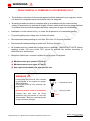
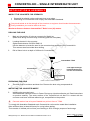
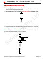
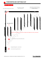
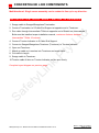
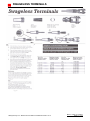
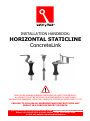
INSTALLATION HANDBOOK: HORIZONTAL STATICLINE ConcreteLink READ ENTIRE HANDBOOK BEFORE INSTALLING ANY SAFETYLINK PRODUCT. ALL PRODUCTS MUST BE INSTALLED IN ACCORDANCE WITH SAFETYLINK’S INSTALLATION HANDBOOK, USING ONLY PRODUCTS SUPPLIED BY SAFETYLINK PTY LTD. FAILURE TO FOLLOW ALL WARNINGS AND INSTRUCTIONS MAY RESULT IN A SERIOUS INJURY OR DEATH. If you are uncertain and need help please email: [email protected] Phone: +61 249 972272 or 1300 789545 | Fax: +61 249 971104 or visit our website www.heightsafety.com Table of Contents INSTALLATION OF A SAFETYLINK STATICLINE SYSTEM USING CONCRETELINK SINGLE UNITS WARNINGS ........................................................................................................................................ 3 MAINTENANCE – PERIODIC INSPECTIONS ......................................................................................... 4 WARRANTIES ..................................................................................................................................... 5 CONCRETELINK – SINGLE END UNIT................................................................................................... 6 PRODUCT CODE: STAT.CONCL006 ....................................................................................................... 6 COMPONENTS ............................................................................................................................. 6 INSTALLATION & ASSEMBLY......................................................................................................... 7 FITTING THE END ANCHOR ASSEMBLY ......................................................................................... 8 CONCRETELINK – SINGLE INTERMEDIATE UNIT ................................................................................. 9 PRODUCT CODE: STAT.CONCL001 ....................................................................................................... 9 COMPONENTS ............................................................................................................................. 9 INSTALLATION & ASSEMBLY....................................................................................................... 10 FITTING THE END ANCHOR ASSEMBLY ....................................................................................... 11 CONCRETELINK – SINGLE CORNER UNIT .......................................................................................... 12 PRODUCT CODE: STAT.CONCL007 ..................................................................................................... 12 COMPONENTS ........................................................................................................................... 12 INSTALLATION & ASSEMBLY....................................................................................................... 13 FITTING THE END ANCHOR ASSEMBLY ....................................................................................... 14 CONCRETELINK SETTING OUT .......................................................................................................... 15 CONCRETELINK LINE COMPONENTS ................................................................................................ 16 SWAGELESS TERMINALS .................................................................................................................. 17 IN CASE OF ACCIDENT ...................................................................................................................... 18 SafetyLink Pty Ltd – StaticLine ConcreteLink Handbook Version 10.14 Back to Table of Contents Page 2 of 18 WARNINGS READ CAREFULLY SOMEONE’S LIFE DEPENDS ON IT The building or structure for the anchorages should be assessed by an engineer, unless it is clear to a competent person that the structure is adequate. All safety procedures must be complied with in accordance with the current safety code(s) of practice(s) for working at heights. Ensure safety at all times by being attached to suitable anchor points and approved safety equipment or approved scaffolding. Installation is to be carried out by, or under the supervision of a competent person. To prevent galling use a spray can of nickel anti-seize. Recommended waterproofing for roof tiles: Sika Flex Co-Polymer Sealant. Recommended waterproofing for metal roof: Silicone Sealant. All threads must be coated with Locktite prior to assembly. (IMPORTANT NOTE: Before applying Loctite 243 use Loctite 7471 primer to activate the surface according to manufacturer’s instructions). SafetyLink StaticLine’s must be installed to roofs below 25 degrees. Maximum user per system is Four (4). Maximum person per span is Two (2). See system information for site specific use. WARNING Locking Hex Nut must be fully screwed up the thread of the eyebolt to expose 30mm of thread. This thread must be fully screwed into the bracket. Intermediate T Bolt (Locktite must be used on all threads) Locking Hex Nut Locking Hex Nut must be firmly tightened onto the bracket to stop the Intermediate T Bolt from unscrewing and to gain maximum strength. SafetyLink Pty Ltd – StaticLine ConcreteLink Handbook Version 10.14 30mm Back to Table of Contents Page 3 of 18 MAINTENANCE – PERIODIC INSPECTIONS All items of equipment which are in regular use shall be subjected to periodic inspection and servicing. These regular scheduled inspections and servicing must be carried out by a competent person (refer to AS/NZS 1891.4:2009 if clarification required or contact SafetyLink). SafetyLink Anchorages (In accordance with AS/NZS 1891.4:2009) ALL ANCHORAGES MUST BE INSPECTED EVERY 12 MONTHS. Procedures to be followed at inspection time: - Visually inspect anchors for signs of deterioration. - The Single End Anchor and Intermediate T Bolts should remain straight, a bent Single End Anchor or Intermediate T Bolt will indicate that the StaticLine has arrested a fall (The design features of the Single End Anchor and Intermediate T Bolts includes the ability to bend like a fishing pole starting from the top and working its way to the bottom, enabling it to use up energy as the Anchor bends whilst lessening the force on the person falling and the attachment point). - Visually inspect the components of the anchor for corrosion, superficial surface marking is permitted while deeper corrosion or pitting would require attention. - Manually (by hand) check the Single End Anchor and Intermediate T Bolt for rigidity and tightness, if the Single End Anchor and Intermediate T Bolt can turn in the anticlockwise direction it will require attention. - Visually inspect the attachment component of the anchorage where practically possible. - Visually inspect the parent structure for modifications or deterioration which might lead to loss of anchorage strength. - Check the condition of line Tensioners and Energy Absorbers. - Check for any evidence of wear, cuts, looseness, extension, interstrand wear, corrosion, stiffness, brittleness or fraying of the steel cable. - Check the integrity of cable terminations. - Check for the presence of contaminants or exposure to a corrosive or extreme environment which could significantly reduce the working load of the StaticLine. - Run the SafeLink Shuttle along the length of the line to verify its correct function. IN ADDITION TO SAFETYLINK PTY LTD EQUIPMENT, ALL ANCILLARY EQUIPMENT MUST BE INSPECTED IN ACCORDANCE WITH APPLICABLE REGULATORY REQUIREMENTS AND THE MANUFACTURER’S INSTRUCTIONS. FOR MAINTENANCE ADVICE AND SERVICES PLEASE CONTACT SAFETYLINK ON 0249 972272 OR 1300 789545 FOR YOUR NEAREST SAFETYLINK INSPECTION SERVICE CENTRE OR EMAIL: [email protected] To download Installation Manuals on other SafetyLink products please visit our website at www.heightsafety.com SafetyLink Pty Ltd – StaticLine ConcreteLink Handbook Version 10.14 Back to Table of Contents Page 4 of 18 WARRANTIES EXTRACT: SafetyLink Pty Ltd STANDARD TERMS AND CONDITIONS 11.1 To the extent permitted by law all implied conditions, warranties and undertakings are expressly excluded. 11.2 Except as provided in this clause the Company shall not be liable for any loss or damage, whether direct or indirect (including consequential losses or damage) arising out of any breach of contract by the Company or any negligence of the Company, its employees or agents. 11.3 Should the Company be liable for a breach of a guarantee, condition or warranty implied by the Australian Consumer Law (not being a guarantee, condition or warranty implied by sections 51, 52 and 53 of that Law) then its liability for a breach of any such condition or warranty express or implied shall be limited, at its option, to any one or more of the following. A) (I) (II) (III) (IV) B) 11.4 in case of Goods the replacement of the Goods or the supply of equivalent Goods. the repair of the goods, the payment of the cost of replacing the Goods or acquiring equivalent Goods. The payment of the cost of having the Goods repaired. Provided that any such Goods are returned to the Company by the Purchaser at the Purchaser’s expense. in the case of services (i) the supply of the services again, (ii) the payment of the cost of having the services supplies again. The Company will not liable for the costs of recovery of the Goods from the field, loss of use of the Goods, loss of time, inconvenience, incidental or consequential loss or damage, nor for any other loss or damage of her than as stated above, whether ordinary or exemplary, caused either directly or indirectly by use of the Goods. 11.5 The Company warrants that at the time of shipment, Products manufactured by it will be free from defects in material and workmanship. In the absence of a modified written warranty, the Company agrees to making good any such defects by repairing the same or at the Company ’s option by replacement, for a period of (1) one year from the date of shipment. This limited warranty applies provided that: (a) (b) (c) (d) (e) (f) defects have arising solely from faulty materials or workmanship; the Products have not received maltreatment, inattention or interference; the Products have been installed in accordance with the Company’s Installation Handbooks using only products supplied by the Company; accessories used with the Products are manufactured by or approved by the Company ; the Products are maintained in accordance with Australian Standard 1891.4 (section 9). you notify any claim under this warranty to SafetyLink in writing to the address below no later than 14 days after the event or occurrence concerning the produce giving rise to the claim and you pay all costs related to your claim. This warranty does not apply to any defects or other malfunctions caused to the Goods by accident, neglect, vandalism, misuse, alteration, modification or unusual physical, environment or electrical stress. Please note that the benefits to the purchaser (as a consumer) given by this warranty are in addition to your other rights and remedies under the Australian Consumer Law. Our goods come with guarantees that cannot be excluded under the Australian Consumer Law. You are entitled to a replacement or refund for a major failure and compensation for any other reasonably foreseeable loss or damage. You are also entitled to have the goods repaired or replaced if the goods fail to be of acceptable quality and the failure does not amount to a major failure. 11.6 If any goods are not manufactured by the Company, the guarantee of the manufacturer thereof shall be accepted by the Purchaser as the only express warranty given in respect of the goods. 11.7 Except as provided in this clause 11, all express and implied warranties, guarantees and conditions under statute or general law as the merchantability, description, quality, suitability or fitness of the Products for any purpose or as to design, assembly, installation, materials or workmanship or otherwise are hereby expressly excluded (to the extent to which they may be excluded by law). PLEASE SEE SAFETYLINK PTY LTD FULL STANDARD TERMS OF CONDITIONS OF SALE FOR FURTHER REFERENCE. SafetyLink Pty Ltd – StaticLine ConcreteLink Handbook Version 10.14 Back to Table of Contents Page 5 of 18 CONCRETELINK – SINGLE END UNIT Product Code: STAT.CONCL006 INSTALLATION OF A SAFETYLINK STATICLINE SYSTEM USING CONCRETELINK SINGLE END UNIT COMPONENTS 14 mm Nuts 14 mm Spring Washers S Cable End Support Single End Anchor Absorbing Bolt Concrete Insert SafetyLink Pty Ltd – StaticLine ConcreteLink Handbook Version 10.14 Back to Table of Contents Page 6 of 18 CONCRETELINK – SINGLE END UNIT Product Code: STAT.CONCL006 INS TALLATION & AS SEMBLY INSPECT THE CONCRETE FOR STRENGTH ConcreteLink should not be positioned close to an edge. Positioning of ConcreteLink must comply with Australian Standards. If any doubt exists as to the strength of the structure an engineer should make the assessment. During installation you must be safe at all times. Maximum distance between Intermediate T Bolts is ten (10) metres. DRILLING THE HOLE 1. Mark out the position of holes on concrete for StaticLine. 2. Locating the steel in the concrete: Digital metal detector: BOSCH DMO 10 Use the detector to locate the steel in the concrete when positioning the ConcreteLink. This ensures steel is avoided when drilling. 3. Drill a 28mm hole to a depth of 100mm for the ConcreteLink. ConcreteLink Single End Unit Lock tight the Single End Anchor into the ConcreteLink Concrete PREPARING THE HOLE 4. The hole must be moisture and dust free. Remove the dust using compressed air. INSTALLING THE CONCRETE INSERT 5. Installing the concrete insert: Recommended chemical anchor is Power-Fast epoxy injection adhesive gel. Read instructions on product carefully. The entire surface of the ConcreteLink unit that is in contact with the concrete must have sufficient adhesive gel, as specified on the product. Concrete anchor has to be proof loaded to a pull-out force of 7.5kN. To comply with Australian Standards each ConcreteLink unit must be tested after installation. Allow sufficient time (at least 48 hours) for curing before testing. Test consists of ultimate pull out force proof loading to 50% of design purpose of anchorage. SafetyLink Pty Ltd – StaticLine ConcreteLink Handbook Version 10.14 Back to Table of Contents Page 7 of 18 CONCRETELINK – SINGLE END UNIT Product Code: STAT.CONCL006 FITTING THE END ANCHOR ASSEMBLY 6. Lock tite the Single End Anchor Absorbing Bolt into the concrete insert. (IMPORTANT NOTE: Before applying Loctite 243 use Loctite 7471 primer to activate the surface according to manufacturer’s instructions). 7. Note: Threads need to have a minimum of six full 360º turns into the ultimate thread. 8. Place the S Cable End Support onto the Single End Anchor Absorbing Bolt and secure with a 14mm Spring Washer and 14mm Nut. Note: Use Locktite on all threads. (IMPORTANT NOTE: Before applying Loctite 243 use Loctite 7471 primer to activate the surface according to manufacturer’s instructions). 9. Ensure S Cable End Support lines up with the run of the Staticline. SafetyLink Pty Ltd – StaticLine ConcreteLink Handbook Version 10.14 Back to Table of Contents Page 8 of 18 CONCRETELINK – SINGLE INTERMEDIATE UNIT Product Code: STAT.CONCL001 INSTALLATION OF A SAFETYLINK STATICLINE SYSTEM USING CONCRETELINK SINGLE INTERMEDIATE UNIT Intermediate T Bolt COMPONENTS Intermediate T Bolt with Locking Hex Nut Concrete Insert SafetyLink Pty Ltd – StaticLine ConcreteLink Handbook Version 10.14 Back to Table of Contents Page 9 of 18 CONCRETELINK – SINGLE INTERMEDIATE UNIT Product Code: STAT.CONCL001 INSTALLATION & ASSEMBLY INSPECT THE CONCRETE FOR STRENGTH ConcreteLink should not be positioned close to an edge. Positioning of ConcreteLink must comply with Australian Standards. If any doubt exists as to the strength of the structure an engineer should make the assessment. During installation you must be safe at all times. Maximum distance between Intermediate T Bolts is ten (10) metres. DRILLING THE HOLE 1. Mark out the position of holes on concrete for StaticLine. (Mark holes along concrete using connecting plate as a template) 2. Locating the steel in the concrete: Digital metal detector: BOSCH DMO 10 Use the detector to locate the steel in the concrete when positioning the ConcreteLink. This ensures steel is avoided when drilling. 3. Drill a 28mm hole to a depth of 100mm for ConcreteLink. Intermediate T Bolt Lock tight the Single Intermediate Anchor into the ConcreteLink ConcreteLink Concrete PREPARING THE HOLE 4. The hole must be moisture and dust free. Remove the dust using compressed air. INSTALLING THE CONCRETE INSERT 5. Installing the concrete insert: Recommended chemical anchor is Power-Fast epoxy injection adhesive gel. Read instructions on product carefully. The entire surface of the ConcreteLink unit that is in contact with the concrete must have sufficient adhesive gel, as specified on the product. Concrete anchor has to be proof loaded to a pull-out force of 7.5kN. To comply with Australian Standards each ConcreteLink unit must be tested after installation. Allow sufficient time (at least 48 hours) for curing before testing. Test consists of ultimate pull out force proof loading to 50% of design purpose of anchorage. SafetyLink Pty Ltd – StaticLine ConcreteLink Handbook Version 10.14 Back to Table of Contents Page 10 of 18 CONCRETELINK – SINGLE INTERMEDIATE UNIT Product Code: STAT.CONCL001 FITTING THE END ANCHOR ASSEMBLY 6. Screw the Locking Hex Nut onto the Intermediate T Bolt making sure it is fully screwed up exposing 30mm of thread, coat threads with Locktite (IMPORTANT NOTE: Before applying Loctite 243 use Loctite 7471 primer to activate the surface according to manufacturer’s instructions). 7. When screwing the Locking Hex Nut onto the stainless steel Intermediate T Bolt make sure it is fully screwed up exposing 30 mm of thread, coat threads with Locktite (IMPORTANT NOTE: Before applying Loctite 243 use Loctite 7471 primer to activate the surface according to manufacturer’s instructions). 8. Note: Threads need to have a minimum of six full 360º turns into the ultimate thread. Intermediate T Bolt Locking Hex Nut 30mm 9. Locktite the Intermediate T Bolt into the concrete insert. 10. Ensure T Bolt lines up with the run of the staticline. SafetyLink Pty Ltd – StaticLine ConcreteLink Handbook Version 10.14 Back to Table of Contents Page 11 of 18 CONCRETELINK – SINGLE CORNER UNIT Product Code: STAT.CONCL007 INSTALLATION OF A SAFETYLINK STATICLINE SYSTEM USING CONCRETELINK SINGLE CORNER UNIT Corner Assembly Single End Anchor Concrete Insert COMPONENTS Corner Unit 14 mm Nuts 14 mm Spring Washers Single End Anchor Absorbing Bolt Concrete Insert SafetyLink Pty Ltd – StaticLine ConcreteLink Handbook Version 10.14 Back to Table of Contents Page 12 of 18 CONCRETELINK – SINGLE CORNER UNIT Product Code: STAT.CONCL007 INSTALLATION & ASSEMBLY INSPECT THE CONCRETE FOR STRENGTH ConcreteLink should not be positioned close to an edge Positioning of ConcreteLink must comply with Australian Standards. If any doubt exists as to the strength of the structure an engineer should make the assessment. During installation you must be safe at all times. Maximum distance between Intermediate T Bolts is ten (10) metres. DRILLING THE HOLE 1. Mark out the position of holes on concrete for StaticLine. 2. Locating the steel in the concrete: Digital metal detector: BOSCH DMO 10 Use the detector to locate the steel in the concrete when positioning the ConcreteLink. This ensures steel is avoided when drilling. 3. Drill a 28mm hole to a depth of 100mm for the ConcreteLink. ConcreteLink Single Corner Unit Lock tight the Single Corner Anchor into the ConcreteLink PREPARING THE HOLE 4. The hole must be moisture and dust free. Remove the dust using compressed air. INSTALLING THE CONCRETE INSERT 5. Installing the concrete insert: Recommended chemical anchor is Power-Fast epoxy injection adhesive gel. Read instructions on product carefully. The entire surface of the ConcreteLink unit that is in contact with the concrete must have sufficient adhesive gel, as specified on the product. Concrete anchor has to be proof loaded to a pull-out force of 7.5kN. To comply with Australian Standards each ConcreteLink unit must be tested after installation. Allow sufficient time (at least 48 hours) for curing before testing. Test consists of ultimate pull out force proof loading to 50% of design purpose of anchorage. SafetyLink Pty Ltd – StaticLine ConcreteLink Handbook Version 10.14 Back to Table of Contents Page 13 of 18 CONCRETELINK – SINGLE CORNER UNIT Product Code: STAT.CONCL006 FITTING THE END ANCHOR ASSEMBLY 6. Lock tite the Single End Anchor Absorbing Bolt into the concrete insert. (IMPORTANT NOTE: Before applying Loctite 243 use Loctite 7471 primer to activate the surface according to manufacturer’s instructions). 7. Note: Threads need to have a minimum of six full 360º turns into the ultimate thread. 8. Place the Corner Unit onto the Single End Anchor Absorbing Bolt and secure with a 14mm Spring Washer and 14mm Nut. 9. Note: Use locktite on all threads. (IMPORTANT NOTE: Before applying Loctite 243 use Loctite 7471 primer to activate the surface according to manufacturer’s instructions). 10. Ensure Corner Unit lines up with the run of the Staticline. SafetyLink Pty Ltd – StaticLine ConcreteLink Handbook Version 10.14 Back to Table of Contents Page 14 of 18 CONCRETELINK SETTING OUT SETTING OUT ConcreteLink Single Corner Unit ConcreteLink Single Intermediate Unit ConcreteLink Single End Unit Swaged/Swageless Tensioner Tension indicator ConcreteLink Single Intermediate Unit Maximum space between ConcreteLink Single Intermediate Unit is ten (10) metres. ConcreteLink Single Intermediate Unit Swaged/Swageless Termination ConcreteLink Single End Unit SafetyLink Pty Ltd – StaticLine ConcreteLink Handbook Version 10.14 Back to Table of Contents Page 15 of 18 CONCRETELINK LINE COMPONENTS Multidirectional: Single corner assembly can be rotated to line up in any direction. INSTALLATION: ROOF SHEET BELOW 25 DEGREES 1. Swage cable to Swaged/Swageless Termination. 2. Connect Termination to S Cable End Support at opposite end to Tensioner. 3. Run cable through Intermediate T Bolts to opposite end of StaticLine (Intermediate T Bolts must be installed as per installation manual, maximum distance between Intermediate T Bolts 10 metres). 4. Connect Tension Indicator to S Cable End Support. 5. Connect a Swaged/Swageless Tensioner (Tensioner) to Tension Indicator. 6. Open out Tensioner. 7. Match up cable so it reaches into Tensioner and mark cable. 8. Cut cable to length. 9. Swage cable to Tensioner. 10.Tension cable till disc on Tension Indicator can be spun freely. Complete layout diagram on previous page. SafetyLink Pty Ltd – StaticLine ConcreteLink Handbook Version 10.14 Back to Table of Contents Page 16 of 18 SWAGELESS TERMINALS SafetyLink Pty Ltd – StaticLine ConcreteLink Handbook Version 10.14 Back to Table of Contents Page 17 of 18 IN CASE OF ACCIDENT A FALL RESCUE PLAN SHOULD BE DEVELOPED PRIOR TO USING SAFETYLINK EQUIPMENT. Persons working at heights should not work alone. It is critical that before using any SafetyLink Systems a fall rescue plan is in place for any persons suspended mid-air following a fall. Serious injury or death can occur in a matter of minutes, particularly if a person’s movement or breathing is restricted or loss of consciousness has occurred. In accordance with your fall rescue plan and appropriate first aid procedures it is essential to remove the person from the suspended position as quickly as possible. In accordance with AS/NZS 1891.4:2009 clause 9.5 EQUIPMENT WHICH HAS ARRESTED A FALL OR SHOWS A DEFECT Any piece of equipment including both personal and permanently installed items, which has been used to arrest a fall or which shows any defect during operator or periodic inspection shall be withdrawn from service immediately and a replacement obtained if necessary. A label indicating the condition or defect should be attached to the equipment, and it should be examined by a competent person who will decide whether the equipment is to be destroyed or repaired if necessary and returned to service. In the latter case, details of any repair shall be documented and a copy given to the operator. DISTRIBUTOR: www.heightsafety.com SafetyLink Pty Ltd – StaticLine ConcreteLink Handbook Version 10.14 Back to Table of Contents Page 18 of 18