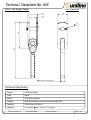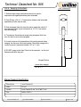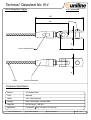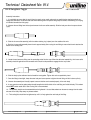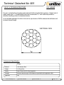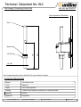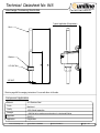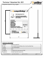
1
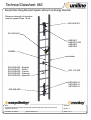
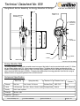
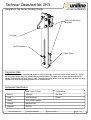
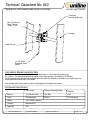
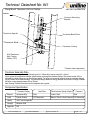
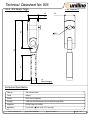
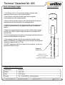
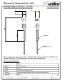
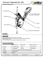
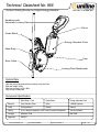
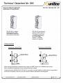
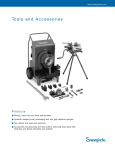
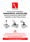
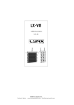
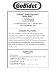
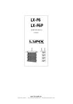
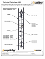
Technical Datasheet: 981
EasyClimber Rung Mounted System with Line Energy Absorber
Minimum strength of structure
must be greater than 12 kN
Ladder
020-669-300
010-669-600
U8S0401
U8S0401-SW
U8S0403
U8S0406
U80802
022-208-600 - English
022-208-601 - Dutch
022-208-602 - French
022-208-603 - German
022-208-604 - Spanish
020-116-200
U8T0400-21
U8T0400-31
U8T0400-41
020-669-400
Notes:
For detailed technical information see individual component data sheets, end user manual and
installation instructions.
Issue Date : 01/12/2006
Revision Number: 01
Approvals:
EN 353 - 1
Sheet 1 of 1
Technical Datasheet: 982
EasyClimber Rung Mounted System without Line Energy Absorber
Minimum strength of structure
must be greater than 18 kN
020-669-301
010-669-601
U8S0401
U8S0401-SW
U8S0403
U8S0406
U80802
Ladder
022-208-600 - English
022-208-601 - Dutch
022-208-602 - French
022-208-603 - German
022-208-604 - Spanish
020-116-200
U8T0400-21
U8T0400-31
U8T0400-41
020-669-400
Notes:
For detailed technical information see individual component data sheets, end user manual and
installation instructions.
Issue Date : 01/12/2006
Revision Number: 01
Approvals:
EN 353 - 1
Sheet 1 of 1
Technical Datasheet No: 939
Rung Mount Anchor Assembly inc Energy Absorber & Clamps
Part No: 020-669-300
A
Section A-A
Scale 1 : 6
Energy Absorber
Assembly
MAX CTRS 350
MIN CTRS 200
Common
Mounting
Bracket
M10
Fasteners
* Swage
Ladder
* Cable
A
Back Plate
* Please order separately
Energy Absorber Data
The energy absorber is design to be mounted across two rungs of the ladder. It can be mounted on both round (12 - 30mm
dia) and square ladder rungs (20 - 40mm) using a common bracket. The ladder which is being considered should be
capable of withstanding fall arrest loads of 12kN, in turn the energy absorber will limit the fall load on the structure and the
user to less than 6kN as advised in EN353:1. The back plate design allows the energy absorber to be fitted to a range of
ladders that have a rung spacing between 200 to 350mm centres.
Component Specification
Spring Assembly
Back Plate
Absorber Fin
Material
Mild Steel
Steel / Acetal / Ph. Bronze
Finish
H.D Galvanized
Spin Galv / Natural / Powder Coated Electropolished
Quality
100% Visual Inspection
Strength
Minimum 15kN
Approvals
EN 353-1
www.unilinesafety.com
Issue Date: 30/08/2006
Stainless Steel
Revision Number: 01
Weather Cover
Fasteners
ABS / PVC
Steel
Natural
H.D Galvanized
Page 1 of 1
Technical Datasheet No: 0974
Rung Mount Top Anchor Including Clamps
Part No: 020-669-301
Common Mounting
Brackets
Fin Plate
M10 Fasteners
Back Plate
Top Anchor Data
The Top Anchor is design to be mounted across two rungs of the ladder. It can be mounted on both round (12 - 30mm
dia) and square ladder rungs (20 - 40mm) using a common bracket. The ladder which is being considered should be
capable of withstanding fall arrest loads of 12kN. The back plate design allows the energy absorber to be fitted to a range
of ladders that have a rung spacing between 200 to 350mm centres.
Component Specification
Back Plate & Fin Plate
Cast Brackets
Material
Mild Steel
Zinc Alloy
Finish
Spin Galvanized
Natural
Quality
100% Visual Inspection
Strength
Minimum 15kN
Approvals
EN 353-1
www.unilinesafety.com
Issue Date: 29/08/2006
Revision Number: 0
Page 1 of 1
Technical Datasheet No: 940
Rung Mount Intermediate Cable Guide inc Clamps
Part No: 020-116-200
Common
Mounting Bracket
M10 Fasteners
Max Torque
15Nm (TYP)
Ladder
Cable Guide
1 x 19, 8mm
Stainless Steel
Cable
Intermediate Bracket Assembly Data
The intermediate bracket assembly can be fitted to both round (12 -30mm dia) and square rungs
(20 - 40mm ). The cable guide has been designed to allow easy passage of the Monkey (Fall Arrester).
The Common Mounting Bracket has two tapped holes in to allow the assembly to be fixed on to a single rung in two
simple operations from the front of the ladder.
Note; Isolation pads are provided to isolate the cable guide from the galvanized ladder.
Component Specification
Cable Guide
Common Mounting Bracket
Fasteners
Material
316 Stainless Steel
Zinc Alloy
Steel
Finish
Electropolished
Natural
H.D Galvanizing
Quality
100% Visual Inspection
Strength
Minimum 6 kN
Approvals
N/A
www.unilinesafety.com
Issue Date: 08/02/07
Revision Number: 02
Page 1 of 1
Technical Datasheet No: 941
Rung Mount Tensioner Unit inc Clamps
Part No: 020-669-400
Ladder
Common Mounting
Bracket
Tensioner Spindle
Tensioner Back Plate
* Tensioner Stud
Tensioner Casing
M10 Fasteners
Max Torque
20Nm (TYP)
* Please order separately
Tensioner Assembly Data
The tensioner assembly can be fitted to both round (12 -30mm dia) & square rungs (20 - 40mm ).
As the system is tensioned the indicator spindle moves up through the tensioner casing. The correct tension (1kN) is
indicated by a white silicone ring on the indicator spindle. The system is tensioned correctly when the complete coloured
ring is just clear of the machined bore. The back plate design allows the energy absorber to be fitted to a range of ladders
that have a rung spacing between 200 to 350mm.
Note: Casting is sealed & isolated from the backplate with a gasket.
Component Specification
Tensioner Casting
Back Plate
Back Indicator Spindle & Spring
Fasteners
Steel
Material
Aluminium Alloy
Steel
Acetal / Steel
Finish
Powder Coated
H.D Galvanized
Natural / Zinc & Yellow Passivate H.D Galvanized
Quality
100% Visual Inspection
Strength
Minimum 6 kN
Approvals
N/A
www.unilinesafety.com
Issue Date: 08/02/2007
Revision Number: 02
Page 1 of 1
Technical Datasheet No: 905
Uni 8 - Roll Swage Toggle
Part: U8S0401
30
30
83
21
75
179
12.5
16
Before Swaging
Component Specification
Material
316 Stainless Steel
Finish
Natural
Quality
100% Visual Inspection
Strength
18kN max permitted arrest load, min break strength 36kN
Approvals
EN795 Class C & EN353-1
Application
For use with
www.unilinesaftey.com
8mm 1x19 or 7x7 wire only
Issue Date: 26/07/2006
Revision Number: 3
Page 1 of 2
Technical Datasheet No: 905
Uni 8 - Roll Swage Toggle
Part No: U8S0401
1. Only Ø 8mm 1x19 or 7x7 construction stainless steel wire cable
approved by Uniline may be used. (system specific).
2. Insert the pair of roller dies for 8mm cable into the cogwheel
synchronising pins of the swaging machine.
3. Ensure that the hydraulic plunger is fully retracted and that the dies are
positioned so that the arrow points in the swaging direction.
4. Attach the swage terminal to the appropriate fixture on the drawing arm
so that the roller dies meet on the swage terminal shank at the desired
position.
5. Apply just enough hydraulic pressure so that the rollers hold the swage
terminal firmly. Mark the cable to length and insert into the bottom of the
terminal throat.
6. Put the transparent guard in position and then apply hydraulic pressure to
draw the terminals between the roller dies.
8. DO NOT swage any further than 70mm in to the connector – as the stud
becomes solid after this point
75
7. After swaging, open the roller dies and release the hydraulic plunger.
Measure the diameter of the swaged area and check against recommended
dimension of approximately 14.07 mm.
Broken out
section view
Swaged Section
(check after swaging)
14.07 - 14.3mm
Swage Machine Specification
Manufacturer
Wireteknik
Model
Type A-250
Size
5/16" Dash 10
Contact
Tel: + (0)46 86436733 - www.wireteknik.se
www.unilinesaftey.com
Issue Date: 26/07/2006
Revision Number: 3
Page 2 of 2
Technical Datasheet No: 946
Roll Swage Toggle + 1st metre of 1 x 19 Cable
Part: U8S0401-SW
30
30
179
21
75
Swaged
Cable 1 x 19
When ordering a pre-swaged system order 1 x U8S0401-SW, plus the required XXm of U80802 (1x19
Stainless Steel Cable). For cable information, refer to Technical Datasheet 925.
Component Specification
Toggle
Material
316 Stainless Steel
Finish
Natural
Quality
100% Visual and dimensional test.
Strength
18kN maximum permitted arrest load, minimum break strength 36 kN.
Approvals
EN353-1
www.unilinesaftey.com
Issue Date: 27/07/06
Revision Number: 1
Page 1 of 1
Technical Datasheet No: 906
Uni 8 - Hex Swage Toggle
Part: U8S0403
30
30
21
180
83
12.5
12.5 Before Swaging
Component Specification
Material
316 Stainless Steel
Finish
Natural
Quality
100% Visual Inspection
Strength
18kN max permitted arrest load, min break strength 36kN
Approvals
EN795 Class C & EN353-1
Application
For use with
www.unilinesaftey.com
8mm 1 x 19 or 7 x 7 wire only
Issue Date: 05/06/06
Revision Number: 3
Page 1 of 2
Technical Datasheet No: 906
Uni 8 - Swaging Instructions
Part: U8S0403
1. Stainless steel swage terminations can only be used in
conjunction with approved stainless steel wire cable.
2. Only Ø 8mm 1x19 or 7 x 7 construction stainless steel wire cable
approved by Uniline may be used.
3. 6mm hexagonal form dies must be used to swage the cable in 6
dis-continuous ‘bites’ to give a dimension of 10.7 to 11mm across
flats after swaging.
4. To achieve a dis-continuous swage using hexagonal ‘bite’ form
dies, the ‘bites’ must not be overlapped.
6. DO NOT swage further than 70mm into the connector - as the stud
becomes solid after this point.
75
5. In order to ensure full compression of the housing material when
swaging, the dies must fully mate together. Check each swage with a
vernier to ensure it measures between 10.7 to 11.1mm
Swaged Section
( check after swaged )
10.7 to 11.1
Manual Swaging Specification
Manufacturer
Izumi Products Co.
Model
EP-410
Contact
Izumi Products Uk Ltd, Tel: 01388 777132
Dies
Model: 12/05/10
www.unilinesaftey.com
Issue Date: 05/06/06
Revision Number: 3
Page 2 of 2
Technical Datasheet No: 914
Uni 8 Swageless Toggle
Part: U8S0406
123
Split Pin
30
83
83
30
22.5mm ACCROSS FLATS
CABLE
COLLET (WITHIN BODY)
Component Specification
Material
316 Stainless Steel
Finish
Machined
Quality
100% Visual Inspection
Strength
Batch Test Strength - minimum 38kN
Approvals
EN 795 Class C + EN 353-1
Applications
For use with
www.unilinesaftey.com
8mm 1x19mm or 7x7 wire only
Issue Date: 02/06/06
Revision Number: 2
Page 1 of 2
Technical Datasheet No: 914
Uni 8 Swageless Toggle
Part: U8S0406
Assembly Instructions
1 - It is advisable to ensure that the end of the wire rope is cut as neatly and evenly as possible before starting to attach any
swage-less termination. At all times take care when handling the wire rope and the groups of strands, avoid kinking or un-laying
of individual strands from their group.
2 - Unscrew the end fitting from the body and remove the tri-cone collet assembly. Slide the body over the wire rope as shown
(right).
3 - Slide the tri-cone collet assembly (with the rubber retaining ring in place) over the outside of the wire.
4 -Push the tri-cone collet assembly down the wire approximately 30mm using the end fitting to ensure that the wire touches the
bottom of the locating hole.
5 - Locate the end connector fitting over the protruding end of the wire rope. When the cable has located fully, the tri-cone collet
assembly should sit against the end connector and it should not be possible to engage the wire any further.
6 - Slide the body up the cable and start to thread the two together. Tighten this as far as possible by hand.
7 - Once the fitting is hand tight, clamp the outer body and use a spanner to tighten the end fitting until this is done up firmly.
8 - Unscrew the assembly and visually inspect to ensure that the cone is seated properly in the main body.
9 - A none corrosive marine grade sealant should be applied to the blind hole in the end fitting and inside the body. This sealant
should NOT contain acetic acid - Dow Corning 744 is recommended.
10 - The assembly should now be reassembled and re-tightened. It is usual that sealant can be seen to emerge from the cable
entrance in the body. Wipe away any excess sealant.
11 - The Locking Nut should then be tightened up until it is firmly against the main body of the fitting.
www.unilinesaftey.com
Issue Date: 01/08/06
Revision Number: 2
Page 2 of 2
Technical Datasheet No: 925
Uni 8 1 x 19 Stainless Steel Cable
Part: U80802
For use in vertical fall arrest systems and overhead Uni-8 horizontal lifeline systems. A higher level of
rigidity means that 1 x 19 cable deflects less than conventional 7 x 7 wire cable and provides a
smoother travelling surface for attachment device.
In an overhead application the wire is to be set to a pre-tension of 5kN to reduce static deflection and
increase the span length.
SECTIONAL VIEW
8
Component Specification
Cable
Material
316 Stainless Steel
Weight
31.20 kg/100m
Quality
Batch Tested & 100% Visual Inspection
Strength
Minimum break strength 45.5kN Maximum permitted load in application 18kN
Approvals
N/A
www.unilinesaftey.com
Issue Date: 02/06/06
Revision Number: 2
Page 1 of 1
Technical Datasheet No: 944
Roll Swage Tensioning Stud & Nut
Part No: U8T0400-21
Typical Application (Easyclimber)
Stud
145
1/2" UNF Nut
237
Washer
1/2" UNF
* For roll swage instructions refer to sheet 947. For use with 8mm 1x19 cable.
Component Specification
Material
316 Stainless Steel
Finish
Machined
Quality
100% Visual Inspection
Strength
< 6kN Not to be used as an end anchor in a horiziontal lifeline
Approvals
EN353-1
Application
Easyclimber
www.unilinesaftey.com
Issue Date: 21/06/2006
Revision Number: 0
Page 1 of 1
Technical Datasheet No: 945
Hex Swage Tensioning Stud & Nut
Part No: U8T0400-31
Typical Application (Easyclimber)
Stud
1/2" UNF Nut
246
142
Washer
1/2" UNF
* Refer to page 906 for swaging instructions. For use with 8mm 1x19 cable.
Component Application
Material
316 Stainless Steel
Finish
Machined
Quality
100% Visual Inspection
Strength
< 6kN Not to be used as an end anchor in a horizontal lifeline
Approvals
EN353-1
Application
Easyclimber
www.unilinesaftey.com
Issue Date: 01/06/2006
Revision Number: 0
Page 1 of 1
Technical Datasheet No: 942
Easyclimber Swageless Tensioning Stud and Nut
Part No: U8T0400-41
Typical Application
(Easyclimber)
Cable
Washer
141
1/2 UNF Nut
Stud
* Refer to technical datasheet 959 for assembly and installation instructions
Component Specification
Material
316 Stainless Steel
Finish
Machined
Quality
100% Visual inspection
Strength
< 6kN Not to be used as an end anchor in a horizointal lifeline
Approvals
EN353-1
Appication
Easyclimber
www.unilinesaftey.com
Issue Date: 04/08/2006
Revision Number: 0
Page 1 of 1
Technical Datasheet No: 960
Easyclimber System ID Tag - English
Part No: 022-208-600
120
5
90
1
Component Specification
Material
Aluminium grade 5251
Finish
Front: Sateen Anodized 25 Micron Coat + Seal. Rear: Milled Finish
Quality
100% Visual Inspection
Stength
N/A
Approvals
Complies with the requirements of EN365
Application
English Easyclimber Systems Only
www.unilinesaftey.com
Issue Date: 01/08/2006
Revision Number: 0
Page 1 of 1
Technical Datasheet No: 961
Easyclimber System ID Tag - Dutch
Part No: 022-208-601
120
5
1
90
Component Specification
Material
Aluminium grade 5251
Finish
Front: Sateen Anodized 25 Micron Coat + Seal. Rear: Milled Finish
Quality
100% Visual Inspection
Stength
N/A
Approvals
Complies with the requirements of EN365
Application
Dutch Easyclimber Systems Only
www.unilinesaftey.com
Issue Date: 01/08/2006
Revision Number: 0
Page 1 of 1
Technical Datasheet No: 962
Easyclimber System ID Tag - French
Part No: 022-208-602
120
5
1
90
Component Specification
Material
Aluminium grade 5251
Finish
Front: Sateen Anodized 25 Micron Coat + Seal. Rear: Milled Finish
Quality
100% Visual Inspection
Stength
N/A
Approvals
Complies with the requirements of EN365
Application
French Easyclimber Systems Only
www.unilinesaftey.com
Issue Date: 01/08/2006
Revision Number: 0
Page 1 of 1
Technical Datasheet No: 963
Easyclimber System ID Tag - German
Part No: 022-208-603
120
5
1
90
Component Specification
Material
Aluminium grade 5251
Finish
Front: Sateen Anodized 25 Micron Coat + Seal. Rear: Milled Finish
Quality
100% Visual Inspection
Stength
N/A
Approvals
Complies with the requirements of EN365
Application
German Easyclimber Systems Only
www.unilinesaftey.com
Issue Date: 01/08/2006
Revision Number: 0
Page 1 of 1
Technical Datasheet No: 964
Easyclimber System ID Tag - Spanish
Part No: 022-208-604
120
5
1
90
Component Specification
Material
Aluminium grade 5251
Finish
Front: Sateen Anodized 25 Micron Coat + Seal. Rear: Milled Finish
Quality
100% Visual Inspection
Stength
N/A
Approvals
Complies with the requirements of EN365
Application
Spanish Easyclimber Systems Only
www.unilinesaftey.com
Issue Date: 01/08/2006
Revision Number: 0
Page 1 of 1
Technical Datasheet No: 938
Vertical Climbing Device
Part No: 010-669-600
Guide Block
Karabiner with
Automatic Locking Gate
Main Body
Clevis
8mm Cable
Cam
Locking Plate Mechanism
System Data
Only one user to be attached to the monkey at any one time
Max user weight 150kg (Only on systems incorporating energy absorber 020-669-302)
Max force on user < 6kN
Only for use on 8mm wire and system with energy absorber at top anchor
Component Specification
Main Body + Cam
Guide Block
Other Components
Material
Cast Stainless Steel
Nylon
Stainless Steel
Finish
Electropolished
Natural
Electropolished
Quality
X-ray / die pen inspected. 100% visual & functional inspection
Strength
Minimum 15kN
Approvals
EN353-1
www.unilinesaftey.com
Issue Date: 30/08/06
Revision Number: 0
Page 1 of 1
Technical Datasheet No: 966
Vertical Climbing Device c/w Integral Energy Absorber
Part No: 010-669-601
Karabiner with
Automatic Locking Gate
Clevis
Guide Block
Energy Absorber Pack
Main Body
Cam
8mm Cable
Locking Plate Mechanism
System Data
Only one user to be attached to the monkey at any one time
Max user weight 136kg
Max force on user in a fall < 6kN
Only for use on 8mm wire
Component Specification
Main Body + Cam
Guide Block
Energy Absorber Pack
Material
Cast Stainless Steel
Nylon
1900dN Polyester
Finish
Electropolished
Natural
Natural
Quality
X-ray / die pen inspected. 100% visual & functional inspection
Visual and Batch
Strength
Minimum 15kN
Min 22kN
Approvals
EN353-1
www.unilinesaftey.com
Issue Date: 30/08/06
Revision Number: 0
Page 1 of 1
Technical Datasheet No: 996
Common Mounting Bracket
(B-Bracket) Fixing Details
Part No: 022-330-500 / 501
022-330-500 is a tapped
mounting bracket ( M10).
This bracket is common to
all Easyclimber Assemblies.
022-330-501 has clearance
holes to suit M10 fasteners.
This bracket is only found
on systems incorporating
an "In Line Energy
Absorber". (Additional
fasteners are supplied).
Fixing Instructions
Mounting on a Square Rung
Mounting on a Round Rung
Note: Orientation of
Bracket to suit rung.
Note: Orientation of
Bracket to suit rung.
Parallel
Parallel
When mounting Easyclimber components onto a ladder you MUST always use a calibrated torque wrench.
Refer to individual the datasheets for the recommended torque settings.
Torque the brackets (022-330-500 & 022-330-501) up evenly to ensure the bracket is pulled onto the rung parallel to
the face of the assembly. Failure to do so, will stress the brackets and bend the mounting plates.
www.unilinesafety.com
Issue Date: 07/02/07
Revision Number:
Page 1 of 1