1
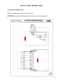
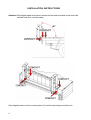
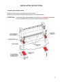
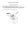
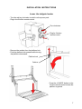
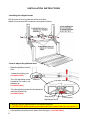
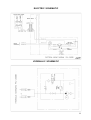
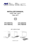
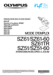
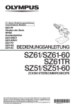
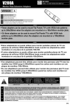
Office:
Factory:
Hauptplatz 23
ALUHEBETECHNIK Tel. (43) 2142 64260
Gesellschaft mbH Fax. (43) 2142 6434
Bahnstraße 34
(43) 2142 64360
(43) 2142 64366
A-2474 Gattendorf
E-Mail:
[email protected]
QUICK INSTALLATION
GUIDE
FOR THE “AHT”
TAIL LIFT
PKL-300.110AL/AL
Max. load capacity: 300kg at 500mm
For Truck: Max. Loading High: 1100mm unloaded
Min. Door Intermediate Width: 1700mm
Gattendorf, August 2008
.
UNPACKING THE TAILGATE LOADER
The tailgate loader is completely assembled and ready for use:
Plus- and MinusCable (7m)
Power Pack
The power pack is in the inside of the main frame and ready for work.
Only the Plus and Minus cable must be connected on the vehicle battery.
2
INSTALLATION INSTRUCTIONS
- Position the tailgate loader:
Center the tailgate loader on the end of truck floor.
ATTENTION: Comply the fitting requirements as shown in the picture below.
3
INSTALLATION INSTRUCTIONS
Attention:The tailgate loader must have a contact on the under side and on the front side
with the truck floor. (on both sides)
If the tailgate loader is in the correct position, fix it with screw clamps onto the truck.
4
INSTALLATION INSTRUCTIONS
- Installing the tailgate loader
Drill 4x holes ø11mm on each side into the truck floor.
Install 4x hex screws M10 on both sides as shown in the picture below.
ATTENTION:
Use a steel plate (approximately. 200x300mm; not supplied) 5mm thick
on the underside of the truck floor for stiffening the truck floor.
5
INSTALLATION INSTRUCTIONS
Energize the power pack
Be sure the vehicle and the tailgate loader are of the same current (12V or 24V).
Fuse is in the power pack. (12V = 16 Amp and 24V = 8 Amp).
Connect the positive cable, directly from the battery, to the starter solenoid. (min. 16mm²)
Connect the negative cable, directly from the battery, to the motor ground. (min. 16mm²)
- Build in between Battery (+) and (+)-Cable the Main Fuse
ow
MAIN FUSE
12V = 125 Ampere
24V = 80 Ampere
FUSE BOX
6
P
to ck
Pa
er
INSTALLATION INSTRUCTIONS
Lower the tailgate loader
- Turn the red key clockwise to switch on the power pack.
- Plug in the 2-button remote control.
Turn clockwise
Plug for 2-button
remote control
- Remove the carbine from the platform lock.
- Push the platform lock upwards while turning
the platform downwards.
Platform lock
Carbine
- Press the „LOWER“ button on the
2-button remote control to lower the
platform to ground.
7
INSTALLATION INSTRUCTIONS
- Installing the tailgate loader
Drill 4x holes ø11mm on the rear of the truck floor.
Install 4x hex screws M10 as shown in the picture below.
- How to adjust the platform level
- Raise the platform to truck
floor.
-
Loosen the locking nut.
(on both sides)
- Turn the adjusting screw
clockwise for lower the
platform tip
(on both sides)
- Turn the adjusting screw anti clockwise for
raise the platform tip
(on both sides)
Stop plate
Locking nut
Adjusting screw
- Check the correct adjustement of the adjusting screws
!!! ATTENTION: Both adjusting screws must have contact with the stop plate !!!
- If the platform level is correct, fasten the locking nut. (on both sides)
8
9
10
ELECTRIC SCHEMATIC
HYDRAULIC SCHEMATIC
11