1
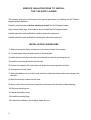
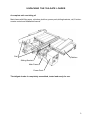
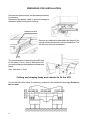
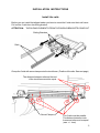
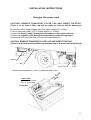
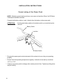
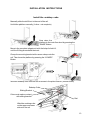
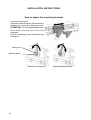
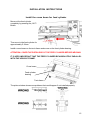
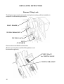
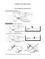
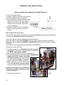
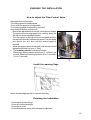
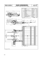
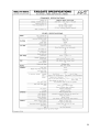
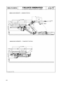
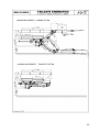
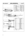
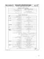
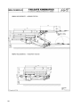
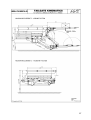
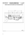
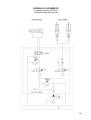
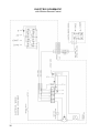
Office:
Factory:
Hauptplatz 23
ALUHEBETECHNIK Tel. (43) 2142 64260
Gesellschaft mbH Fax. (43) 2142 6434
Bahnstraße 34
(43) 2142 64360
(43) 2142 64366
A-2474 Gattendorf
E-Mail:
[email protected]
INSTALLER’S MANUAL
FOR THE “AHT”
TAIL LIFT
UTK-1000ST/AL
UTK-2000ST/AL-SS
with double-acting feed cylinder
LEFT HAND DRIVER
AU
Gattendorf, 2011
SERVICE QUALIFICATIONS TO INSTALL
THE TAILGATE LOADER
The installer should be well trained in the proper procedure for installing the AHT before
beginning the installation.
Carefully read the manual before starting to install the AHT tailgate loader.
Only mature adults, age 18 and above, should install the AHT tailgate loader.
Installer should be well qualified for installing hydraulic equipment.
Installer should be well qualified for installing the electrical equipment.
INSTALLATION GUIDELINES
1) Remove bumpers, lights, tool box etc. from rear of vehicle if necessary.
2) Cut and shape the body and chassis to fit the tailgate.
3) Install the rails onto the truck frame and check them with the checking device.
4) Install the mounting brackets onto the rails.
5) Position the tailgate unit under the truck. Adjust the correct position and fix it.
6) Energize the Power Pack.
7) Raise the platform to truck floor level and fix the sliding brackets with screw clamps onto
the rails.
8) Weld the end stop cubes onto the rails.
9) Move out the feed cylinder and install the cross beam with the feed cylinder bearing.
10) Remove the tilting lock.
11) Adjust the platform level.
12) Install the warning flags.
13) Finish the installation: Mount lights, spare tire, etc.
2
UNPACKING THE TAILGATE LOADER
A complete unit consisting of:
Main frame with lifting arms, cylinders, platform, power pack,sliding brackets, rail, 2 buttonremote-control and installation manual.
Rail
Platform
Sliding Bracket
Main Frame
Power Pack
The tailgate loader is completely assembled, tested and ready for use.
3
PREPARING FOR INSTALLATION
Remove rear lights, bumper, tool box and spare wheel,
if necessary.
Disconnect the battery cable to prevent damage to
the battery while working on truck body.
Subframe Tie-down
Remove any obstruction attached to the frame of the
vehicle that would interfere with the installation. The
rail will cover the truck mainframe.
Rail
The measurement of dimension A and B must
be the same. If A is >1mm in difference of B,
you have to attach a sheet between rail and main
frame.
max. Tolerance +/-1mm
Cutting and shaping body and chassis to fit the UTK
Cut out the rear of the frame, if necessary, as shown in the installation drawings. Reinforce
the cut outs.
4
INSTALLATION INSTRUCTIONS
Install the rails
Before you can install the tailgate loader you have to mount the 2 rails onto the truck frame.
Pull out the 2 rails from the sliding bracket.
ATTENTION:
THE SLIDING ELEMENTS FROM THE SLIDING BRACKETS COME OUT.
Sliding Brackets
Rails
Clamp the 2 rails with screw clamps onto the truck frame. (Position of the rails: See next page)
The distance between rails and the end
of the truck frame must be equal.
Screw Clamps
The 2 rails must be parallel.
The distance between truck
frame and rails must be equal
(max. +/- 1mm)
5
INSTALLATION INSTRUCTIONS
Install the rails
Positionthe the rails as shown in the kinematic drawings. (Page 20 - 28)
Place 1 checking device onto the rails as shown in the picture below.
CONTACT between rail and
checking device.
Fasten the screw if the correct
width is adjusted.
Check the width of the rails with 1 checking device on the front, middle and rear.
If the difference between front, middle and rear is >1mm, you have to attach a sheet between
rail and main frame.
max. Tolerance +/-1mm
Check the width of the
rails on the front,
middle and rear side.
6
INSTALLATION INSTRUCTIONS
Install the rails
Now place the second checking device onto the rail. One on the front and the other on the
rear of the rail.
If you looking behind from the truck, the 2 checking devices must be parallel.
Distance must be equal
WRONG - The 2 checking devices are not parallel ==> The 2 rails are not parallel (See
Page 5).
NOT PARALLEL
If all dimension are OK and the 2 rails are parallel, drill holes ø16 in the truck frame (12 per rail)
12 holes ø16 per rail
Drill 2 holes in the truck frame, put a bolt in each one and secure. Then drill all other holes.
NUMBER OF SCREWS PER RAIL: 12 pieces M16x50
THEN REMOVE ALL SCREW CLAMPS.
7
INSTALLATION INSTRUCTIONS
Install the mounting brackets
Loosen the 4 screws per mounting bracket and remove the mounting brackets from the
main frame.
Cross bar
Loosen the 4 screws per
mounting bracket.
Remove the 2 mounting
brackets
Move the mounting brackets onto the rails.
ATTENTION: ALL SLIDING ELEMENTS MUST PLACE IN THE SLIDING BRACKETS
(6 SLIDING ELEMENTS PER SLIDING BRACKET)
Loose all nuts
8
INSTALLATION INSTRUCTIONS
Install the mounting brackets
ATTENTION: The Angle between mounting bracket and cross bar must be 90°
You can adjust the angle with the 2 adjusting nuts on the inner side of cross bar.
If the Angle is correct, you have to lock the 2 cross bars with the locking nut.
Locking nut
Adjusting nut
Locking nut
The mounting brackets must move easily with hand.
9
INSTALLATION INSTRUCTIONS
Position the Tailgate
Place the tailgate with a fork lift under the truck. The
mainframe of the tailgate must be under the mounting
brackets. The tailgate must be centric to the truck.
Raise the complete tailgate with a
fork lift to the correct position and
install the mounting brackets onto
the main frame. Don’t fasten the 4
screws per mounting bracket
complete.
ATTENTION:
THE ANGLE BETWEEN MOUNTING BRACKET AND MAIN FRAME MUST
BE 90°. THE POSITION OF THE MAIN FRAME MUST BE CENTRIC TO
THE TRUCK.
If the tailgate is in the correct
position, fasten all screws at the
mounting brackets. (4 per mounting
bracket)
4 screws per mounting
bracket
10
INSTALLATION INSTRUCTIONS
Energize the power pack
CAUTION: REMOVE TRANSPORT FILLER CAP AND INSERT DIPSTICK:
(There is no air hole in filler cap and the pump or reservoir will be destroyed)
Be sure the vehicle and the liftgate are of the same voltage (12V or 24V).
Fuse is in the power pack. (12V = 25 Amp and 24V = 16 Amp).
Connect the positive cable, directly from the battery, to the starter solenoid.
Connect the negative cable, directly from the battery, to the motor ground.
Complete all other electrical work. (Connect all control switches)
CAUTION: REMOVE TRANSPORT FILLER CAP AND INSERT DIPSTICK:
(There is no air hole in transport filler cap and the pump or reservoir will be destroyed)
Batterie
+ / - cable
Power Pack
- Build in between Battery (+) and (+)-Cable the Main Fuse
ow
MAIN FUSE
12V = 125 Ampere
24V = 80 Ampere
er
P
to ck
Pa
FUSE BOX
11
INSTALLATION INSTRUCTIONS
Correct wiring of the Power Pack
NOTE: All battery power leads must have a core area not less than 35mm² (at DC-Motor
2.0kW)and be double insulated.
Connect both battery cables (+ and -) directly from the battery to the power pack.
ATTENTION:
By fixing the battery cable on the starter switch, you must hold up the
lock nut.
Battery Cable
Lock Nut
NI
TUR
NG
HO
LD
UP
Starter Switch
* Energize the power pack and actuate each of the valves to be sure they are operating
properly.
* Please check the operating temperature regularly. It should not increase by more than
-20°C to +70°C.
* Check a new power pack for leakage after a short period of time. Tighten any fittings that
may be leaking.
12
INSTALLATION INSTRUCTIONS
Install the endstop cube
Manually slide the tail lift out to the end of the rail.
Unfold the platform manually (1x time - not complete)
Now raise the
platform to the truck floor level by pressing the
“RAISE”-Button.
Move in the complete tailgate unit with the help of a fork lift,
until the 2 lifting arms attach the truck.
Clamp the mounting bracket with a screw clamp onto the
rail. Then lower the platform by pressing the “LOWER”Button.
==>
Weld the endstop cube onto the rail as shown in the picture below. (on both sides)
Endstop Cube
Sliding Bracket
Cube must make a contact
with sliding bracket
Rail
Weld the endstop cube
on the upper and lower
side onto the rail
13
INSTALLATION INSTRUCTIONS
How to adjust the mounting brackets
- Loosen the locking nut
- Adjust the easy movement of the mounting
brackets by turning the adjusting screw.
ATTENTION: The mounting brackets must
move easily, but they don’t have any
clearance.
- Hold the adjusting screw and fasten the
locking nut.
locking nut
adjusting screw
Loosen the locking nut
14
Adjust the sliding bracket
INSTALLATION INSTRUCTIONS
Install the cross beam for feed cylinder
Move out the feed cylinder
completely by pressing the „OUT“Button.
Then move in the feed cylinder for
approximately 5-10mm.
Install a cross beam on the truck frame and screw on the feed cylinder bearing.
ATTENTION: COVER THE PISTON ROD OF THE FEED CYLINDER BEFORE WELDING.
IT IS VERY IMPORTANT THAT THE FEED CYLINDER BE ABSOLUTELY PARALLEL
WITH THE VEHICLE FRAME.
Cross beam
Feed cylinder
bearing
Truck frame
The pictures below show some problems that could happen if not installed properly.
15
INSTALLATION INSTRUCTIONS
Remove Tilting Lock
The tilting lock prevents the automatic leveling from working until the installation is
complete. It is the last thing to remove.
MAIN FRAME
TILTING BRACKET
TILTING LOCK
LIFT
CYLINDER
Remove the screw M6x25 on both sides.
(Before removing the screw M6x25 the platform must
be raised from ground)
SCREW M6x25
for TILTING LOCK
TILTING BRACKET
16
FINISHING THE INSTALLATION
How to adjust the platform level
1) Unfold the platform completely.
2) Loosen the locking nut on both sides.
Locking nut
Screw to adjust
the platform level
Adjust the platform:
- Turn out the screw for raise the platform tip.
Turn out the screw for raise
the platform tip
- Turn in the screw for lower the platform tip.
Turn in the screw for lower
the platform tip
contact
contact
contact
no contact
3) If the platform level is correct, fasten the locking nut on both sides.
17
FINISHING THE INSTALLATION
How to adjust the maximum Lifting Pressure
1)
2
3)
4)
Turn on the Main Switch
Open the platform and lower to the ground.
Lower the platform tip to the ground.
Load the platform with the maximum rated
load and one person. Be sure to place
the load in the center of platform and at
1000mm from the vehicle. (Check the
vehicle data plate)
5) Press the “Raise”-Button. If the platform
does not raise, the relief valve is set
too low.
How to adjust the relief valve:
The relief valves are sealed at the factory. The seals must not be removed unless authorized
by the factory. Warranty is void if seal is broken.
There are 2 different places to adjust the hydraulic pressure:
Relief Valve 3A is to adjust the LIFTING pressure. Factory setting is 220bar (3190PSI).
Relief Valve 3B is to adjust the SLIDE IN and SLIDE OUT pressure. Factory setting is 100bar
(1450PSI).
All 2 relief valves are adjustable from 50-250bar (700-3600PSI).
* Adjustment of the relief valve:
a) To adjust pressure, a calibrated pressure gauge is
required and it should be connected at the test point plug
(8). NOTE: 1bar equals 14.5PSI
b) Remove the seal and cover from the adjusting nut.
c) Turn the adjusting screw with a hex wrench, clockwise (for
higher pressure) or counter-clockwise
(for lower pressure). Be sure to keep an
eye on the pressure gauge. The maximum
pressure should be 220bar (3190PSI).
d) When pressure is correct, lock the cap
screw and check the pressure again to
be sure it has not changed. Seal the cover.
Caution: Never bottom the relief valve.
The power pack and/or hydraulic system
could be damaged.
8
6) Turn the main switch off.
3B
18
3A
FINISHING THE INSTALLATION
How to adjust the Flow Control Valve
Adjustable flow control valve:
The Lifting speed is not adjustable.
The In and Out speed is not adjustable.
The lowering speed is adjusted by position 7.
How to adjust the flow control valve:
- Be sure the adjustable flow control valves are not closed.
To regulate the lowering speed, first carefully loose the
M4 lock nut at the adjustable throttle.
- Turn the cap nut to the right to lower the speed and turn
the cap nut to the left to increase the speed. Turn the screw
one quarter turn at a time until the desired speed is
reached.
- When the desired speed is reached, hold the cap nut and
tighten the M4 lock nut (max. 1.5Nm).
• The lowering speed should be as follows:
Maximum lowering speed should be 6” (150mm) per
second. (Maximum lowering speed is 40” in 7 seconds).
(1 m in 7 seconds)
7
Install the warning flags
Mount the warning flags with 3 rivets on each flag.
Finishing the Installation
- Lubricate all grease fittings.
- Check all Locking brackets.
- Check the oil level.
- Check all hydraulic hoses and cylinders for tightness.
19
20
21
22
23
24
25
26
27
28
HYDRAULIC-SCHEMATIC
for pump head PK-UTK-2000
for double-acting feed cylinder
29
ELECTRIC-SCHEMATIC
with 2-Button-Remote Control
30