1
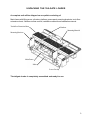
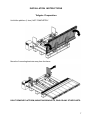
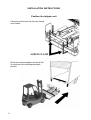
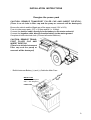
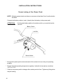
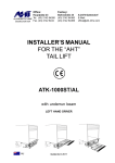
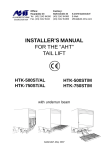
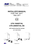
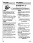
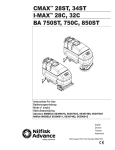
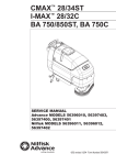
Office:
Factory:
Hauptplatz 23
ALUHEBETECHNIK Tel. (43) 2142 64260
Gesellschaft mbH Fax. (43) 2142 6434
Bahnstraße 34
(43) 2142 64360
(43) 2142 64366
A-2474 Gattendorf
E-Mail:
[email protected]
INSTALLER’S MANUAL
FOR THE “AHT”
TAIL LIFT
ATK-500ST/AL
ATK-750ST/AL
ATK-500ST/ST
ATK-750ST/ST
without underrun beam
LEFT HAND DRIVER
AU
Gattendorf, August 2009
SERVICE QUALIFICATIONS TO INSTALL
THE TAILGATE LOADER
The installer should be well trained in the proper procedure for installing the AHT before
beginning the installation.
Carefully read the manual before starting to install the AHT tailgate loader.
Only mature adults, age 18 and above, should install the AHT tailgate loader.
Installer should be well qualified for installing hydraulic equipment.
Installer should be well qualified for installing the electrical equipment.
INSTALLATION GUIDELINES
1) Remove bumpers, lights, tool box etc. from rear of vehicle if necessary.
2) Install the truck floor extension on truck body.
3) Cut and shape the body and chassis to fit the tailgate.
4) Unfold the platform and place the mounting brackets on each side. Clamp the main frame
onto the pallet.
5) Place the tailgate loader under the truck at its approximate location.
6) Energize the Power Pack.
7) Raise the platform above the pallet.
8) Install the mounting device.
9) Position the main frame to its final position.
10) Place the mounting brackets on the truck frame.
11) Remove mounting device and tilting lock.
12) Adjust the platform level.
2
UNPACKING THE TAILGATE LOADER
A complete unit will be shipped on one pallet consisting of:
Main frame with lifting arms, cylinders, platform, power pack,mounting brackets, truck floor
extension sheet, 2 button-remote-control, installation material and installation manual.
Truckfloor Extension Sheet
Platform
Mounting Material
Mounting Bracket
Main Frame
Pallet
Power Pack
The tailgate loader is completely assembled and ready for use.
3
PREPARING FOR INSTALLATION
Remove rear lights, bumper, tool box and spare wheel,
if necessary.
Disconnect the battery cable to prevent damage to the
battery while welding.
Subframe Tie-down
Remove any obstruction attached to the frame of the
vehicle that would interfere with the installation. The
mounting brackets will cover the mainframe and subframe.
Mounting bracket
The ATK-Tailgate requires a truck floor extension sheet
at the rear of the vehicle. The extension sheet allows
the required space for the platform to be stowed.
The extension sheet can be fitted inside of truck body.
4
PREPARING FOR INSTALLATION
If truck floor extension sheet is installed at the rear of vehicle:
It’s necessary to weld the truck floor extension onto the truck body.
WELDING DETAILS: STITCH WELD ONLY
* Weld 25mm Miss 300mm TOP AND BOTTOM AS REQUIRED
EXTENSION MUST BE
FLUSH WITH TRUCK FLOOR
TRUCK FLOOR
EXTENSION
5
PREPARING FOR INSTALLATION
Cutting and shaping body and chassis to fit the ATK
See the drawings “body preperation” from page 22, to shape the body to fit the folded tailgate.
Trim and grind all rough ends after cutting the chassis and the body before painting.
6
INSTALLATION INSTRUCTIONS
Tailgate Preparation
Unfold the platform (1 time). NOT COMPLETELY
Move the 2 mounting brackets away from the frame.
DON’T REMOVE PLATFORM, MOUNTING BRACKETS, PINS OR ANY OTHER PARTS.
7
INSTALLATION INSTRUCTIONS
Position the tailgate unit
- Clamp the main frame with 2 screw clamps
onto a pallet.
SCREW CLAMP
- Place the complete tailgate unit with a fork
lift under the truck to the approximately
position.
8
INSTALLATION INSTRUCTIONS
Energize the power pack
CAUTION: REMOVE TRANSPORT FILLER CAP AND INSERT DIPSTICK:
(There is no air hole in filler cap and the pump or reservoir will be destroyed)
Be sure the vehicle and the liftgate are of the same current (12V or 24V).
Fuse is in the power pack. (12V = 25 Amp and 24V = 16 Amp).
Connect the positive cable, directly from the battery, to the starter solenoid.
Connect the negative cable, directly from the battery, to the motor ground.
Complete all other electrical work. (Connect all control switches)
CAUTION: REMOVE TRANSPORT FILLER CAP AND
INSERT DIPSTICK:
(There is no air hole in transport
filler cap and the pump or
reservoir will be destroyed)
- Build in between Battery (+) and (+)-Cable the Main Fuse
ow
MAIN FUSE
12V = 125 Ampere
24V = 80 Ampere
er
P
to ck
Pa
FUSE BOX
9
INSTALLATION INSTRUCTIONS
Correct wiring of the Power Pack
NOTE: All battery power leads must have a core area not less than 16mm² and be double
insulated.
Connect both battery cables (+ and -) directly from the battery to the power pack.
ATTENTION:
By fixing the battery cable on the starter switch, you must hold up the
lock nut.
Battery Cable
Lock Nut
NI
TUR
NG
HO
LD
UP
Starter Switch
* Energize the power pack and actuate each of the valves to be sure they are operating
properly.
* Please check the operating temperature regularly. It should not increase by more than
-20°C to +70°C.
* Check a new power pack for leakage after a short period of time. Tighten any fittings that
may be leaking.
10
INSTALLATION INSTRUCTIONS
Position the Main Frame
-
Press the “RAISE”-Button to raise the platform approximately to the final position.
(see the drawing below)
ATTENTION:
Don’t raise the platform higher than 620mm (Liftarm
length=625) or 700mm (Liftarm length=715 & 750mm)
above the pallet - lift cylinders are without end stop!!!
Lift cylinder will be demaged!!!
FORBIDDEN
Never raise the liftarm at the stabilizer tube!!
FOR ALL MODELS FROM
SERIAL NO. 8800
STOP PLATE
MAINFRAME
LIFTARM
The maximum height is reached when the stop
plate at the liftarm has a contact with the
mainframe.
11
INSTALLATION INSTRUCTIONS
Installing the mounting device
-
Install mounting device at platform bearing (on both sides) as shown in the picture below.
MOUNTING
DEVICE
-
Place the tailgate loader with a fork lift and the help of mounting devices to its final
position (See drawings below). Be sure that the platform is in the middle of the truck body.
MOUNTING
DEVICE
FORKLIFT
12
INSTALLATION INSTRUCTIONS
Installing the mounting device
-
Be sure that both mounting devices make a contact with the truck floor extension
sheet. (on lower and back side)
TRUCK FLOOR
EXTENSION
SHEET
MOUNTING
DEVICE
VERY IMPORTANT FOR CORRECT POSITION OF THE TAILGATE
-
If the tailgate loader is in the correct position, fix the mounting devices with screw clamps.
SCREW CLAMP
TRUCK FLOOR
EXTENSION SHEET
MOUNTING DEVICE
13
INSTALLATION INSTRUCTIONS
Position the main frame
-
Press the “Lower”- Button and raise the complete tailgate unit with the forklift at the
same time until the main frame is in the right position.
LOWER
BUTTON
RAISE
- Place the mounting brackets to its exact final position.
- Before you can fix the mounting brackets, you have to displace the power pack.
Loosen the 4 screws
M10x25 on the power
pack
Now displace the power pack
It is not necessarry to remove any hydraulic hoses, fittings
and electric wirings.
14
INSTALLATION INSTRUCTIONS
Install mounting brackets
- Place the mounting brackets to its exact final position.
- Clamp the mounting brackets on the truck frame.
Mounting Bracket
Truck Main Frame
Screw Clamp
Check the
right-angled
- Fix the mounting brackets on the main frame.
- Drill 16mm (5/8”) holes into chassis and mounting brackets.
Screw M16 (5/8”) is 8.8 Strength (Grade 8) Max. Torque 195 Nm (145 ft lbs.)
Drill two holes in each bracket, put a bolt in
each one and secure. Then drill the other holes.
Truck Main Frame
4 HOLES
ø 16mm (5/8“)
Screw Clamp
Mounting Bracket
NUMBER OF SCREWS PER MOUNTING BRACKET: 4 pieces M16x50
15
INSTALLATION INSTRUCTIONS
Remove mounting device
- 1)
- 2)
- 3)
- 4)
Press the”Raise”-Button short.
Remove screw clamp.
Lower the platform for ~20cm by pressing the “Lower”-Button.
Remove mounting device.
RAISE
LOWER
REMOVE
Remove all other screw clamps and the pallet.
16
REMOVE
INSTALLATION INSTRUCTIONS
Adjust the position of power pack
- Mount the power pack again. Fasten the 4 screws M10x35.
- Adjust the position of power pack.
Loosen the two
M10 screws.
- Adjust the power pack to the right position
(see in the picture below).
- Fasten the two M10 screws.
Truck Body
Power Pack
17
INSTALLATION INSTRUCTIONS
Remove Tilting Lock
The tilting lock prevents the automatic leveling from working until the installation is
complete. It is the last thing to remove.
TILTING LOCK
Remove the screw M6x55 on both sides.
(Before removing the screw M6x55 the platform must
be raised from ground)
SCREW M6x55
for TILTING LOCK
MAIN FRAME
TILTING BRACKET
18
INSTALLATION INSTRUCTIONS
How to adjust the platform level
- Raise the platform nearly up to truck floor level.
Adjusting
screw M16
-
Loosen the locking nut.
(on both sides)
Joint plate
Locking nut
- Turn the adjusting screw clockwise for
lower the platform tip
(on both sides)
- Turn the adjusting screw anti clockwise for
raise the platform tip
(on both sides)
- Check the correct adjustement of the adjusting screws
On lower position, both adjusting screws must have contact with the joint plate.
OK
WRONG
contact
contact
contact
no contact
- If the platform level is correct, fasten the locking nut. (on both sides)
19
FINISHING THE INSTALLATION
Install a platform lock
Mount a mechanical platform lock according to the picture below.
EYE ON TRUCK BODY
EYE ON PLATFORM
CHAIN WITH HOOK
It’s also possible to mount other forms of platform lock to prevent the tailgait against
abnormal lowering.
20
21
22
23
24
25
26
27
28
29
ELECTRIC AND HYDRAULIC DIAGRAM
with mechanical hose burst valve
with 2-Button-Remote-Control
with 1-Button-Hand-Control
38
I N D E X
Page
Service qualifications
2
Installation guidelines
2
Unpacking the tailgate loader
3
Preparing for installation
4-7
Position the tailgate unit
8
Energize the power pack
9 - 10
Position the main frame
11
Installing the mounting device
12 - 13
Position the main frame
14
Installing the mounting brackets
15
Remove mounting device
16
Adjust the position of power pack
17
Remove tilting lock
18
How to adjust the platform level
19
Install a platform lock
20
Data Sheets
Electric and hydraulic diagram
21 - 37
38