1
Master Controller User Manual for v2.2.1 Firmware (Manual Revision 1.02) Last updated 06/17/2009 Master Controller User Manual NOTICE This manual, software and electronic circuitry are copyrighted. All rights reserved. Under the copyright laws, this manual, software and electronic circuitry may not be copied, in whole or in part without written prior consent of JTECH Communications, Inc. (JTECH). All information provided in this document is carefully prepared and offered in good faith as a guide in the installation, use and servicing of our products. Installers must ensure that the final installation operates satisfactorily within the relevant regulatory requirements. JTECH accepts no responsibility for incorrect installation. JTECH reserves the right to change products, specifications, and installation data at any time, without notice. JTECH makes certain limited warranties with respect to defective diskettes, documentation and electronic circuitry. Please see the associated information contained on this page. SOFTWARE LICENSE STATEMENT This manual, software and electronic circuitry are protected by international copyright laws. Under the copyright laws, this manual, software and electronic circuitry may not be copied, in whole or in part without written prior consent of JTECH, except in the normal use of the software to make an archival copy of the software for the sole purpose of backing up the software and protecting your investment from loss or damage. LIMITED WARRANTY With respect to the physical documentation and physical electronic circuitry enclosed herein, JTECH warrants the same to be free of defects in materials and workmanship for a period of one year from the date of purchase. In the event of notification within the warranty period of defects in material or workmanship, JTECH will replace the defective diskettes, documentation and electronic circuitry. The remedy for breach of this warranty shall be limited to replacement and shall not encompass any other damages, including but not limited to loss of profit, and special, incidental, consequential, or other similar claims. JTECH specifically disclaims all other warranties, expressed or implied, including but not limited to implied warranties of merchantability and fitness for a particular purpose with respect to defects in the documentation and electronic circuitry, and the program license granted herein, in particular, and without limiting operation of the program license with respect to any particular application, use, or purpose. COMPLIANCE NOTICES CE (EUROPE) JTECH declares under our sole responsibility that the product Master Controller to which this declaration relates, is in conformity with the following standards and/or other normative documents. ‐ EN 55022: 1994 +A1: 1995 +A2: 1997 ‐ EN 301 489 ‐2 v1.3.1 (2002‐08) ‐ EN 301 489 ‐7 v1.3.1 (2005‐11) ‐ EN 60950‐1: 2001 We hereby declare that all essential radio test suites have been carried out and that the above named product is in compliance to all the essential requirements of Directive 1999/5/EC. The conformity assessment procedure referred to in Article 10(5) and detailed in Annex IV of Directive 1999/5/EC has been followed with the involvement of the following notified body: Bay Area Compliance Laboratory Corporation, 1274 Anvilwood Ave., Sunnyvale, CA 94089, USA Identification mark: 1313 (Notified Body Number) The technical documentation relevant to the above equipment can be made available for inspection on application to JTECH. Page 2 © JTECH Communications, Inc. User Manual Master Controller COMPLIANCE NOTICES (continued) ROHS & WEEE To minimize the environmental impact and take more responsibility to the earth we live, JTECH hereby confirms that the following product series comply with Directive 2002/95/EC (RoHS) and 2002/96/EC (WEEE) of the European Parliament. SAA (AUSTRALIA) To ensure compliance with ACA Technical Standards, this equipment is labeled with a Telecommunications Compliance Label. For safety reasons, this equipment should only be connected to compliant telecommunications equipment in accordance with the manufacturer’s instructions. FCC (USA) Part 15 This equipment has been tested and found to comply with FCC Rules and Regulations, Part 15 with the limits of a Class B digital device, designed to provide reasonable protection against harmful interference. This equipment generates, uses and can radiate frequency energy and if not installed and used in accordance with the instructions, may cause interference harmful to radio communications. On the base of the equipment is a label containing an FCC Registration Number, if applicable. Part 68 This equipment complies with Part 68 of the FCC rules. Located on the equipment is a label that contains, among other information, the FCC registration number and ringer equivalence number (REN.) If requested, this information must be provided to the telephone company. The REN is used to determine the quantity of devices which may be connected to the telephone line. Excessive REN’s on the telephone line may result in the devices not ringing in response to an incoming call. In most, but not all areas, the sum of the REN’s should not exceed five (5.0). To be certain of the number of devices that may be connected to the line, as determined by the total REN’s contact the telephone company to determine the maximum REN for the calling area. This equipment cannot be used on the telephone company‐provided coin service. Connection to Party Line Service is subject to State Tariffs. If this equipment causes harm to the telephone network, the telephone company will notify you in advance that temporary discontinuance of service may be required. If advance notice isn’t practical, the telephone company will notify the customer as soon as possible. Also, you will be advised of your right the file a complaint with the FCC if you believe it is necessary. The telephone company may make changes in its facilities, equipment, operations, or procedures that could affect the operation of the equipment. If this happens, the telephone company will provide advance notice in order for you to make the necessary modifications in order to maintain uninterrupted service. If trouble is experienced with this equipment, please contact: JTECH Communications, Inc., 6413 Congress Avenue, Suite 150, Boca Raton, FL 33487, Ph: 561‐997‐0772 If the trouble is causing harm to the telephone network, the telephone company may request you to remove the equipment from the network until the problem is resolved. This equipment uses the following USOC jacks: RJ11C It is recommended that the customer install an AC surge arrester in the AC outlet to which this device is connected. This is to avoid damaging the equipment caused by local lightning strikes and other electrical surges. IC (INDUSTRY CANADA, INDUSTRIE CANADA) This class B digital apparatus complies with Canadian ICES‐003. © JTECH Communications, Inc. Page 3 Master Controller User Manual SAFETY AND GENERAL INFORMATION Important information on safe and efficient operation. Read this information before using the unit Electromagnetic Interference/Compatibility Nearly every electronic device is susceptible to electromagnetic interference (EMI) if inadequately shielded, designed, or otherwise configured for electromagnetic compatibility. Potentially Explosive Atmospheres Do not operate the Master Controller in any area with a potentially explosive atmosphere. Sparks in a potentially explosive atmosphere can cause an explosion or fire resulting in bodily injury or even death. Areas with potentially explosive atmospheres include fueling areas such as below decks on boats, fuel or chemical transfer or storage facilities, areas where the air contains chemicals or particles such as grain, dust, or metal powders, and any other area where you would normally be advised to turn off your vehicle engine. Areas with potentially explosive atmospheres are often but not always posted. Blasting Caps and Areas To avoid possible interference with blasting operations, do not use the Master Controller near electrical blasting caps, in a blasting area, or in areas posted: “Turn off two‐way radio.” Obey all signs and instructions. SELV/TNV‐3 warning The TITAN Telephone Router and Master Controller have been assessed as having TNV‐3 and SELV circuits, all non PSTN ports shall be connected to approved SELV circuits or an approved isolation unit shall be used. PSTN Line Cord warning To comply with PSTN safety requirements the use of 26AWG line cords is recommended. Page 4 © JTECH Communications, Inc. User Manual Master Controller Table of Contents 1 ABOUT THE MASTER CONTROLLER................................................................................................... 8 1.1 Introduction ...........................................................................................................................8 1.2 Master Controller Kit..............................................................................................................9 1.3 Front Panel...........................................................................................................................10 1.3.1 LED Indicators.................................................................................................................... 10 1.3.2 Connectors ........................................................................................................................ 11 1.4 Rear Panel............................................................................................................................12 1.4.1 Mains Input‐ Rear.............................................................................................................. 12 2 INSTALLATION ............................................................................................................................... 13 2.1 Enclosure Mounting ............................................................................................................. 13 3 BASIC CONFIGURATION ................................................................................................................. 14 3.1 Connecting ...........................................................................................................................14 3.2 Logging In.............................................................................................................................16 3.3 Logging Out ..........................................................................................................................16 3.4 Entering a License Key .......................................................................................................... 17 3.5 Regional Settings..................................................................................................................18 3.6 IP Settings ............................................................................................................................19 3.7 Setting up Users ................................................................................................................... 21 3.8 Setting up Ports.................................................................................................................... 24 3.9 Setting up Gateways.............................................................................................................27 3.10 Setting up Contacts ..............................................................................................................28 3.11 Setting up Groups................................................................................................................. 30 3.12 Sending a Message ...............................................................................................................32 3.13 Viewing Sent Messages ........................................................................................................35 3.14 Changing Your Password ......................................................................................................37 4 ADVANCED CONFIGURATION......................................................................................................... 38 4.1 Inbox....................................................................................................................................38 4.2 Site Survey ...........................................................................................................................40 4.3 Setting up Escalations...........................................................................................................41 4.4 Setting up Common Messages ..............................................................................................45 4.5 Advanced Message Settings..................................................................................................46 4.6 Updating the Master Controller’s Firmware ..........................................................................48 4.7 Database Tools.....................................................................................................................50 4.8 Display Unit Temperature.....................................................................................................51 4.9 Port Communications ........................................................................................................... 52 4.10 System Log ...........................................................................................................................54 4.11 Support Contact Information ................................................................................................ 55 4.12 PDA, Cell /Mobile Phone Client.............................................................................................57 5 GATEWAY CONFIGURATION EXAMPLES ......................................................................................... 58 5.1 SMTP (email)........................................................................................................................ 59 5.1.1 Master Controller Settings ................................................................................................ 59 5.1.2 Master Controller Input Settings....................................................................................... 61 5.1.3 Master Controller Output Settings.................................................................................... 62 5.1.4 Configuring an incoming Email System using Outlook Express......................................... 63 © JTECH Communications, Inc. Page 5 Master Controller User Manual Table of Contents 5.1.5 Configuring an incoming Email System using Microsoft Exchange Server........................ 66 System with Alarm Inputs (Connected to an Alarm Router)...................................................69 5.2.1 Master Controller Settings ................................................................................................ 69 5.3 PBX Paging with a TITAN Telephone Router .......................................................................... 75 5.3.1 Setting up the System ....................................................................................................... 75 5.3.2 Master Controller Settings ................................................................................................ 75 5.3.3 Sending a Message............................................................................................................ 75 5.4 Configuring a Generic Gateway............................................................................................. 76 5.4.1 Fire Panel Example ............................................................................................................ 77 5.4.2 More Examples.................................................................................................................. 78 5.4.3 Real World Example .......................................................................................................... 78 5.4.4 Generic InterfaceHints ...................................................................................................... 81 5.5 POCSAG Paging over IP.........................................................................................................82 5.5.1 Setting up the System ....................................................................................................... 82 5.5.2 Master Controller Settings ................................................................................................ 82 5.5.3 SmartPage‐E Settings ........................................................................................................ 84 5.5.4 Sending a Message............................................................................................................ 88 5.6 TAP Protocol using Dialup Modem........................................................................................89 5.6.1 Setting up the System ....................................................................................................... 89 5.6.2 Master Controller Settings ................................................................................................ 89 5.6.3 Sending a Message............................................................................................................ 91 5.7 SMS (Short Message Service to Cell Phones using Cellular Router) ........................................92 5.7.1 Setting up the System ....................................................................................................... 92 5.7.2 Master Controller Settings ................................................................................................ 92 5.7.3 Sending SMS...................................................................................................................... 95 5.7.4 Receiving SMS ................................................................................................................... 95 5.8 Messaging to Cisco System ................................................................................................... 97 5.8.1 Setting up the System ....................................................................................................... 97 5.8.2 Master Controller Settings ................................................................................................ 97 5.8.3 System Operation............................................................................................................ 100 5.8.4 Sending a Message.......................................................................................................... 100 5.9 Messaging to Kirk Wireless Server 600v3 System ................................................................ 102 5.9.1 Setting up the System ..................................................................................................... 102 5.9.2 Master Controller Settings .............................................................................................. 103 5.9.3 Sending a Message.......................................................................................................... 110 5.10 Messaging to Kirk 500 and 1500 Systems ............................................................................ 112 5.10.1 Setting up the System ..................................................................................................... 112 5.10.2 Master Controller Settings .............................................................................................. 113 5.10.3 Sending a Message.......................................................................................................... 119 5.11 Messaging to Spectralink Handsets..................................................................................... 120 5.11.1 Setting up the System ..................................................................................................... 120 5.11.2 Master Controller Settings .............................................................................................. 121 5.11.3 System Operation............................................................................................................ 123 5.11.4 Sending a Message.......................................................................................................... 124 5.12 Reporting ........................................................................................................................... 125 5.12.1 Setting up the System ..................................................................................................... 125 5.12.2 Master Controller Settings .............................................................................................. 125 5.2 6 APPENDIX .....................................................................................................................................126 6.1 Cable pin‐outs .................................................................................................................... 126 Page 6 © JTECH Communications, Inc. User Manual Master Controller Table of Contents 6.2 6.3 6.4 6.5 RS485 Communications ...................................................................................................... 128 ASCII Character Set............................................................................................................. 129 Further Help and Support ................................................................................................... 130 Technical Specifications...................................................................................................... 131 About This Handbook This manual is designed to assist with installation of the TITAN Master Controller. Every component of the system is described in a separate section of the manual with step‐by‐step instructions to facilitate hardware installation and software configuration. Conventions NOTE: A note preceded with this symbol indicates secondary information pertaining to the topic under discussion. IMPORTANT: A Right‐pointing arrow followed by text in this manner presents important information. ▲ WARNING: Warnings like this alert you to the fact that you might damage your equipment or lose data if you don't follow instructions carefully. © JTECH Communications, Inc. Page 7 Master Controller 1
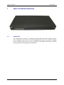
User Manual ABOUT THE MASTER CONTROLLER 1.1
Introduction The TITAN Master Controller is a message routing module with built in paging encoder, alarm management and various forms of messaging protocol inputs and outputs. Messages can be routed to and from any port. A multi‐user multi‐lingual web browser interface provides generalized messaging and configuration. Page 8 © JTECH Communications, Inc. User Manual 1.2
Master Controller Master Controller Kit Your Master Controller Kit will contain: •
Master Controller Unit •
IEC Mains power cable •
Pack including 2 x rack ears, 6 x black countersunk screws, 4 x rubber feet •
Communications cables o
1 x Green – Crossover serial cable (RJ45 to RJ45) o
1 x Black – Serial cable (RJ45 to DB9 female) o
1 x Blue – Straight through cable (RJ45 to RJ45) o
1 x Red – Crossover Ethernet cable (RJ45 to RJ45) •
This Master Controller Installation Manual •
A CD containing manuals and configuration programs © JTECH Communications, Inc. Page 9 Master Controller 1.3
User Manual Front Panel 1.3.1
LED Indicators •
Power Indicator Power (Yellow) ‐ Indicates that power is applied to the back of the unit and that it is operational. •
Ethernet Indicators IP Activity (Green) ‐ Indicates activity on the network IP Link (Green) ‐ Indicates device is successfully connected to the network. •
Transmitter Indicators PTT (Yellow) ‐ Indicates that the externally connected POCSAG transmitter is currently busy transmitting (“Keyed up”) Data (Red) ‐ Indicates POCSAG data activity. IMPORTANT: The Transmitter indicators will operate as described above if used with a TITAN Transmitter which uses PTT invert and Data non‐invert. If these PTT or Data settings are changed to suit third party transmitters, then these LED’s may stay on permanently and flash off when there is activity. •
Modem Indicator Modem (Yellow) ‐ Indicates that the modem port is in use (off hook). •
RS232/RS485 Indicators TX (Red) ‐ Indicates transmit data activity on the RS232/RS485 ports. RX (Green) ‐ Indicates receive data activity on the RS232/RS485 ports. Page 10 © JTECH Communications, Inc. User Manual 1.3.2
Master Controller Connectors All the connectors are of RJ45 type (8 pin ‐ socket) except for the modem connector which is a RJ12 type (4pin ‐ socket) Pin numbers, socket view, viewed from the front of the unit. RJ45 RJ12 Transmitter Interface Connector The Master Controller allows the use of an external paging transmitter. The transmitter socket is shown in the figure below. Pin No. 1 2 3 4 5 6 7 8 Name NC NC NC PTT GND DATA NC BUSY Description Unused Unused Unused Push To Talk/ Transmit (active‐low‐input) Ground Digital Data (active‐high‐input) Unused Carrier detect (active‐low‐output) RS232 Serial Port Connector (COM 1, 2, 3, 4) Pin No. 1 2 3 4 5 6 7 8 Name DSR/RI CD DTR GND RXD TXD CTS RTS Dir IN IN OUT IN OUT IN OUT Description Data Set Ready / Ring Indicator Carrier Detect Data Terminal Ready System Ground Receive Data Transmit Data Clear to Send Request to Send RS485 Connectors (COM 4) Pin No. Name Description 1 2 3 4 5 6 7 8 LINE+ LINE‐ NC SGND NC NC NC NC RS485 A termination RS485 B termination Signal Ground © JTECH Communications, Inc. Page 11 Master Controller User Manual Modem Connector (Line 1) Pin No. 1 2 3 4 1.4
Rear Panel 1.4.1
Mains Input‐ Rear Name NC Tip Ring NC Description Tip Ring This IEC connector is used to supply power to the unit. You can plug 110‐240VAC 50/60Hz into here without the need to change power supplies or settings (input is auto‐sensed). You will have been supplied with a mains lead in the Master Controller kit which will plug straight into this connector. Page 12 © JTECH Communications, Inc. User Manual Master Controller 2
INSTALLATION 2.1
Enclosure Mounting Before mounting the enclosure, you will need to decide where to place the unit. The Master Controller can be desk mounted or installed into a standard 19 inch rack frame. Your Master Controller package contains four adhesive rubber feet which can be placed on the underside of the unit if you wish to desk mount it. If the unit is to be rack mounted you will need to attach a pair of rack ears. Your Master Controller package contains a set of rack ears and six screws. Use a Phillips screwdriver to attach the ears to the chassis. Use the supplied IEC mains power lead to connect 110‐240VAC 50/60 Hz supply to the Master Controller unit. © JTECH Communications, Inc. Page 13 Master Controller 3
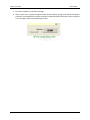
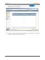
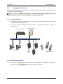
BASIC CONFIGURATION 3.1
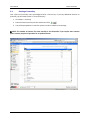
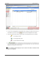
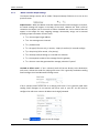
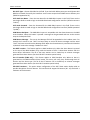
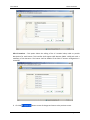
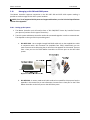
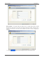
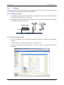
Connecting User Manual In order to view the user interface, you must first connect to the Master Controller via its Ethernet port. There are two ways that you can connect to the unit. 1. Directly with a PC or laptop using the supplied crossover Ethernet cable (red RJ45 ‐ RJ45). 2. By connecting the unit to a local area network (LAN) by connecting it to a spare port or to a switch/hub, using the supplied straight through Ethernet cable (blue RJ45 ‐ RJ45). Once you have plugged in the unit you can use a utility called “IPDiscover” to locate your Master Controller on the network and start a web session with the unit. This program is included on the CD included in the package. Run the program and you will see all TITAN products on the network. NOTE: DHCP is enabled by default. If no DHCP server is found on the network, the default IP of 192.168.0.1 will be used. In the example above, there is a Master Controller on the network at IP Address 192.168.100.234. If you would like to configure the IP settings of this unit you may click the “CfgIP” button. You can then turn off DHCP if it is not required or change the units IP Address. Page 14 © JTECH Communications, Inc. User Manual Master Controller IMPORTANT: If you cannot connect to the Master Controller, you should set your PC’s network card IP Address to be on the same subnet as the Master Controller. For example if the Master Controller is set to 192.168.1.100 you should set your PC IP Address to 192.168.1.x. (where x is 1‐
255) NOTE: Default password is the same as the maint password, which should be left blank. If you are happy with the IP settings, highlight the unit in the IPDiscover program and click the “Web” button. A browser window will open shortly displaying the login screen as shown below. © JTECH Communications, Inc. Page 15 Master Controller 3.2
User Manual Logging In At the Login Screen you will be prompted to enter your details. The default login details are: Username: maint Password: leave blank The New Message Screen will then be shown. NOTE: The Master Controller has many features and protocols that are enabled by license key. As a result not all features explained in the manual may be available on your Master Controller. For more details contact your place of purchase. 3.3
Logging Out To logout at any time, simply click the Log Off button. Page 16 © JTECH Communications, Inc. User Manual 3.4
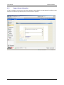
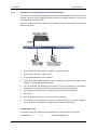
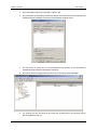
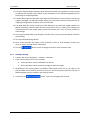
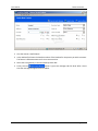
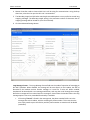
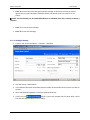
Master Controller Entering a License Key Your system will normally come preconfigured with a license key. If you buy additional features or protocols, you will need to enter in a new license key. 1. Click Setup ‐> Licensing 2. Paste the new license key into the text box and click . 3. You will be prompted to re‐start the system in order to load the new settings. NOTE: The number of contacts for some interface is also licensable. If you require more contacts please contact you place of purchase for an updated license. © JTECH Communications, Inc. Page 17 Master Controller 3.5
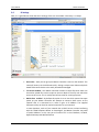
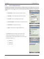
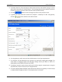
User Manual Regional Settings As part of the initial setup, time and date settings need to be configured. Click Setup ‐> Time Zone. •
Time server – This is the time server on the internet that your Master Controller will periodically try to synchronize with in order to keep the correct time. •
Current time – Shows the current time on Master Controller •
Time zone – This setting helps the Master Controller calculate the current local time. •
Manually Set time – If your Master Controller is never connected to the internet you can manually set the time in this field in 24hr format. ▲ WARNING: The time and date is not stored if the unit is turned off. If you are not using a time server, the time will need to be manually entered each time the unit is turned on. When finished making changes on this page, click to save all new settings. Page 18 © JTECH Communications, Inc. User Manual 3.6
Master Controller IP Settings Next, it is a good idea to check that the IP settings of the unit are suitable. Click Setup ‐> IP Setup. •
Host name – Here you can give your Master Controller a name on the network. This name will show up in the IPDiscover utility. Giving a unique name allows multiple IP based TITAN series devices to be easily located and managed. •
FTP server enabled – Your Master Controller contains a simple ftp server which can be used to upload files such as scripts to the unit. Maint is the only user which has access to this server. This is usually best left set to No for security purposes. •
DHCP client enabled – By default this option is set to Yes which means that upon power up your Master Controller will attempt to contact a DHCP server on the network that it is connected to in order to gain an IP Address. The supplied IPDiscover utility can then be used to locate units on your network. In some situations, such as if your network has no DHCP server or when interfacing with the TITAN Telephone Router or SmartPage‐E, the Master Controller may need a fixed IP Address. In this case you will need to fill in the IP Address, IP Mask, Default Gateway and DNS field below. © JTECH Communications, Inc. Page 19 Master Controller User Manual •
IPv6 enabled – IPv6 (Internet Protocol Version 6) is the latest revision of the Internet Protocol. IPv6 was designed as an evolutionary set of improvements to the current IP Version 4. The most obvious improvement in IPv6 over the IPv4 is that IP addresses are lengthened from 32 bits to 128 bits. This extension anticipates considerable future growth of the Internet and provides relief for what was perceived as an impending shortage of network addresses. Your Master Controller supports IPV6 for future compatibility. This field is normally set to No. •
Syslog enabled – Syslog is a simple way of performing logging of some of the Master Controller’s activities. This includes all messages processed, when users log on/off, when a gateway goes up/down or when certain settings are changed such as IP Settings. The Master Controller will need a network connection and a Syslog server on the network in order to use this function. If this function is required enter the IP Address of the Syslog server in the field below. The supplied CD contains a freeware Syslog server that you can use to log these messages. •
Reporting Server/Reporting Server Port – See the Configuration Examples section of this manual for details on setting on Reporting. •
Ethernet stats – Click this button to view statistics regarding the Ethernet port. •
Network stats – Click this button to view statistics regarding the network. When finished making changes on this page, click to save all new settings. Page 20 © JTECH Communications, Inc. User Manual 3.7
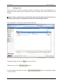
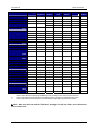
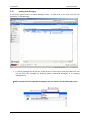
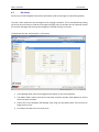
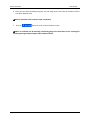
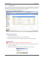
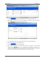
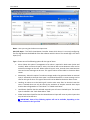
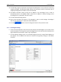
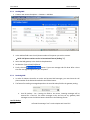
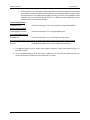
Master Controller Setting up Users Users have access to log into the Master Controller and perform certain tasks depending on the privileges that they have been given. By default the only user installed is maint, which has full access to all areas. NOTE: In order to add more users you will need a license key that allows for more than 1 user on the system. See the Setup ‐> Licensing screen to view the current licensing restrictions. Click on Recipients ‐> Users to see a list of currently setup users. To edit and existing user click the link next to that user. To delete a user, click the button. To send a message to another user, click the in the users Inbox. button. The message will appear © JTECH Communications, Inc. Page 21 Master Controller To add a new user, click the User Manual button. The following window will be shown. Enter the Name and Password for the new user you wish to setup and then click the Edit Privileges button. The following screen will then be shown. NOTE: Some of the privileges shown above wont been shown unless the Master Controller has certain licenses installed. Tick the options that this new user should have access to. The table on the next page explains in more detail the access rights for each tick box. When finished, click the button. Page 22 © JTECH Communications, Inc. User Manual Master Controller Messaging Edit Recipients
Edit Interfaces
Manage Users Manage Alarms Nursecall Staff Allocation
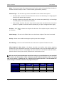
Send Message Sent items View sent items of others Inbox Recipients: Delete Create Edit Gateways: Delete Create Edit Users: Delete Create Edit Disconnect session View active alarms Create and edit ADM inputs Common messages: Delete Create Edit Settings: Messaging IP Regional Licensing Temperature Database Tools Update Firmware Site Survey Change own password View Staff Allocation Menu View Nursecall Menu Users require both the Messaging and Manage Users privilege to view the sent items of others. Users require both the Edit Interfaces and Manage Alarms privilege to create/edit alarm inputs. Users require both the Edit Recipients and Edit Interfaces privilege to perform these actions. NOTE: Most users will not need the “Edit Users” privilege. This will not allow a user to disconnect users or create users. © JTECH Communications, Inc. Page 23 Master Controller 3.8
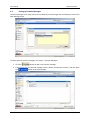
User Manual Setting up Ports A myriad of external devices and third party products can communicate with the Master Controller via its physical “Ports”. The data may be in formats such as RS232, RS485, TCP/IP, POCSAG or via modem In order to communicate with another device via its “Ports”, Master Controller must first be told some basic information about the connection such as data speed, bandwidth, baud rate etc. Click on Interfaces ‐> Ports to see the list of ports. To edit the properties of a port, click the link. There are four different port types available in a Master Controller: 1. RS232/485 – If data is to come in or out of one of the Com ports, the port will need to be configured here. The properties on this page will need to match that of the equipment you are connecting to. Once the settings are correct, click the button. IMPORTANT: Com4 can be set to RS232 or RS485. Page 24 © JTECH Communications, Inc. User Manual Master Controller 2. IP – The IP port will be used if you are interfacing with products such as the TITAN SmartPage‐E using the Ethernet connection. In most cases Method will be set to TCP. In the Bandwidth drop down box select the connection speed between the Master Controller and the equipment it is being interfaced to. The Port refers to the port that the Master Controller will use for TCP/IP connections. This must match that of the external equipment. If the port you are configuring is an input, select Yes for the Listen on this port field. NOTE: Internet based messaging protocols like WCTP, SNPP, Cisco, Kirk 600/6000, SMTP (email), are implemented directly upon TCP/IP sockets, and thus do require a port to be configured. Once the settings are correct, click the button. 3. Modem – Your Master Controller contains an internal modem which can be used to dial out to a remote system using the TAP protocol. The Baud, Data bits, Parity and Stop bit fields must match that of the other system that is being dialed. If the Master Controller unit is being dialed for TAP in, the Answer Rings field determines how many rings it takes before the Master Controller will pick up the line. © JTECH Communications, Inc. Page 25 Master Controller User Manual To ensure compliance with regulatory requirements, the country that the Master Controller resides in must be selected in the Country field. The Speaker option can be used to give an audible indication of line activity. You will be able to hear the modem dialing, answering calls and handshaking if this option is enabled. Once the button. settings are correct, click the 4. Transmitter – This port will be used if the Master Controller is being connected directly to a paging transmitter. If connecting to a standard JTECH transmitter, select Standard Transmitter in this field. If using a non‐Jtech transmitter select Custom. If Custom is selected, you will then be able to configure all properties of the transmitter. Consult the documentation that came with your paging transmitter for more information on the required settings. Once the settings are correct, click the button. Page 26 © JTECH Communications, Inc. User Manual 3.9
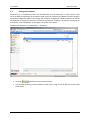
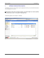
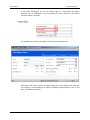
Master Controller Setting up Gateways Whilst the Ports screen explained above is used to configure basic information about the connection, the Gateway screen is used to configure protocol specific settings. A Gateway uses a Port to implement the various input and output messaging protocols upon. Thus providing physical / communications layer independence. Each gateway is of a particular protocol type. The gateway maybe either input, output, or both if the protocol supports concurrent sending and receiving. (e.g. SMS, Email etc) NOTE: For a list of gateways that the Master Controller supports, see the Technical Specifications section of the Appendix. The Master Controller is essentially a messaging router – it can take in any of the input protocols and send it out as any of the output protocols. Click on Interfaces ‐> Gateways to see the list of gateways. In the example below there are two gateways configured. At any time, a gateway can be individually started/stopped, deleted or edited by clicking the links next to each. To create a new gateway, click the button. Examples of how gateways are configured are outlined later in the Gateway Configuration Examples section later in this manual. © JTECH Communications, Inc. Page 27 Master Controller 3.10
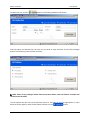
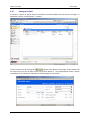
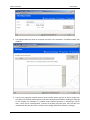
User Manual Setting up Contacts A contact is a person or device setup in the Master Controller database that can be sent messages. To administer contacts, click Recipients ‐> Contacts. button at the bottom of the page. A new window will Create a new contact by clicking the be shown where you will be able to enter the contact details in. The example below shows a person named Bob, who is wearing an alphanumeric POCSAG pager on cap code 8. Page 28 © JTECH Communications, Inc. User Manual Master Controller NOTE: The “Send Via” drop down box contains a list of all Gateways configured on the Master Controller. This setting determines how messages to this contact are routed. After you have entered all the details, click the button. The new entry will now be shown on the contact screen. Try sending a test message to the new contact by highlighting the row and pressing the button. NOTE: You can sort by Name or Local ID by clicking the column heading. © JTECH Communications, Inc. Page 29 Master Controller 3.11
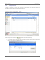
User Manual Setting up Groups A Group is a collection of contacts, users, escalations or other groups. This allows easy dispatch of messages to multiple recipients by selecting just one group. To administer contacts, click Recipients ‐> Groups. Create a new group by clicking the button at the bottom of the page. 1. A new window will be shown where you will be able to enter the name of the group, local id and priority. Then click the Edit Members button. Page 30 © JTECH Communications, Inc. User Manual Master Controller 2. You will then be prompted to select the recipients for this group. Type the name of the recipient button. followed by the NOTE: You cannot search by Local ID in this field – you must search by the assigned name. 3. In the example below we will choose two contacts named John and Tim. NOTE: Hold the [CTRL] key to multi‐select recipients. NOTE: You can filter the recipient list by contact, group, escalation, user or all types by clicking the relevant buttons. 4. After selecting the required recipients click the followed by . button, followed by 5. The group will then be shown on the Group Screen. © JTECH Communications, Inc. Page 31 Master Controller 3.12
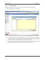
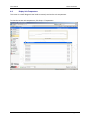
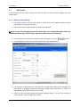
User Manual Sending a Message Messages can be manually sent to any recipient from the Master Controller’s web interface. To test this, click Messaging ‐> New Message. 1. In the Find Recipients field, start typing the name of the recipient you wish to contact. Any matches will show up in a list. You can see in the example below that we have started to type “Jo” and the matches “Johns Email” and “Johns Pager” have been found. 2. Your mouse or the up/down/enter keys can be used to select the required recipient from the matching results. Once selected, it will be added to the Current Recipients list. Page 32 © JTECH Communications, Inc. User Manual Master Controller NOTE: You can also type a Local ID in the Find Recipients field. The Master Controller will look up the Local ID and find the recipient it corresponds to. 3. A message can now be typed to the recipient. If required, the current date or time can be inserted into the message by clicking the or buttons. button. This will make the message jump 4. If the message is important, click the to the front of the message queue and it will be sent with an urgent flag. © JTECH Communications, Inc. Page 33 Master Controller User Manual 5. Click the Send button to send the message. 6. After a short time, a popup will appear under the Send button, giving confirmation that Master Controller has attempted to send the message. For detailed status information and any possible error messages, check the Sent Messages screen. Page 34 © JTECH Communications, Inc. User Manual 3.13
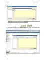
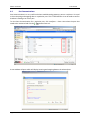
Master Controller Viewing Sent Messages A list of sent items is kept in the Sent Messages screen. To view these at any time, click this click Messaging ‐> Sent Messages. 1. To view all messages sent by the unit, choose All in the “Select user to view” drop down box. You can also filter sent messages by selecting System (automated messages) or by choosing individual users. NOTE: A maximum of 20 completed messages per user are shown in the Sent Messages screen. © JTECH Communications, Inc. Page 35 Master Controller User Manual 2. Double click on any message to view all of its details such as the status or error information. NOTE: If a message has been sent to multiple recipients, this screen will show the status for each individual. 3. If a message is in the Escalating state, it can be manually canceled by selecting the message and then pressing the button. link is a useful option as it allows the Sent Messages Screen to be 4. The detached. If you have a dual monitor setup, the detached window can be maximized on one screen while other programs can be opened in the other screen. 5. The “Show control characters” tick box can enable display of non‐printable characters within sent messages. 6. Various icons will be shown under the Status column. The meaning for each icon is described below. ‐ This message has been received or read ‐ You have replied to this message ‐ This message has been dispatched ‐ This message is queued ‐ Sending of this message failed ‐ This message has been sent NOTE: Not all devices that are sent messages, support “receive” or “read” notification. Page 36 © JTECH Communications, Inc. User Manual 3.14
Master Controller Changing Your Password If you need to change your password, click Setup ‐> Password. This option is used to change the password for the currently logged in user. 1. Simply enter your old password followed by the new password two times. 2. Click the button to save the new password. © JTECH Communications, Inc. Page 37 Master Controller 4
User Manual ADVANCED CONFIGURATION 4.1
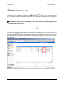
Inbox The Inbox is where messages sent to you as a user, are stored. To view your Inbox, click Messaging ‐> Inbox. For example if you were logged in as maint and you manually sent a message to a recipients email address, that message would appear on their computer as an email. This recipient can answer your message by selecting reply, typing a message and selecting send. This message reply would then appear in your Inbox. 1. When you have unread messages waiting in your Inbox, an alert in the bottom right corner will show “You have unread messages” as can be seen below. A sound will also play through the computer speakers if the “Unread messages sound notification” tick box on the Inbox Screen is checked. The number of unread messages will also be shown in brackets next to Inbox under the Messaging menu bar. Page 38 © JTECH Communications, Inc. User Manual Master Controller 2. To see all of the message details, simply double click a message. The details will be shown in a new window. You can even click the button to send a message back to the sender. 3. Various icons will be shown under the Status column. The meaning for each icon is as follows. ‐ This message is unread ‐ This message has been read ‐ You have replied to this message link is a useful option as it allows the Inbox Screen to be detached. If you 4. The have a dual monitor setup the detached window can be maximized on one screen while other programs can be opened in the other screen. NOTE: A maximum of 100 messages per user are stored in the Inbox. A maximum of 200 messages are stored globally. © JTECH Communications, Inc. Page 39 Master Controller 4.2
User Manual Site Survey Site survey is a useful diagnostic tool used to periodically send out messages via a particular gateway. This tool is often used to the test coverage area of a paging transmitter. This is accomplished by setting up the site survey function to send out a message to a pager every 15 seconds. You can now walk around the site with the pager and ensure that messages are received correctly in all areas. To administer this tool, click Interfaces ‐> Site Survey. 1. In the Message field, enter the message that will appear on the receiving device. 2. The Address field is where you enter the cap code, cell phone number, email address etc for the device you wish to contact. 3. Choose the correct Gateway and Message Type using the drop down boxes and click Start to begin the site survey. 4. Click Stop to end the site survey at any time. Page 40 © JTECH Communications, Inc. User Manual 4.3
Master Controller Setting up Escalations Occasionally it is a requirement that a call unconditionally must be answered – in some cases it could mean the difference between life and death. Under these circumstances the Master Controller employs escalation management and priority queuing. The escalation management enables a sequence of staff to be contacted, at varying time intervals, until the call is answered. In addition, the priority system ensures that the call is sent immediately, by moving it to the front of the queue. To administer escalations, click Recipients ‐> Escalations. 1. Click the button to create a new escalation. 2. In the popup window, give the escalation a useful name, assign a Local ID and then click the Edit Steps button. © JTECH Communications, Inc. Page 41 Master Controller User Manual 3. The popup window will show all recipients currently in the escalation. Click Add to add a new recipient. 4. You can start typing the recipient name or local id of the contact you wish to add, or simply click the Find link to manually add recipients. Also select the delay period before sending the message to this recipient. For example in a situation where Master Controller is monitoring a freezer door, a chef may be contacted after 1 minute of the door being left open, but if he does not respond and close the door after 3 minutes, the message could be escalated to a manager. Page 42 © JTECH Communications, Inc. User Manual Master Controller 5. Click the button to return to the Edit Steps screen. © JTECH Communications, Inc. Page 43 Master Controller User Manual 6. Once you have finished adding recipients, the Edit Steps screen will show all members and the time delay between each. NOTE: A maximum of 10 escalation steps are allowed. 7. Click the button to return to the Escalations screen. NOTE: An escalation can be manually canceled by going to the Sent Items screen, selecting the escalating message and pressing the End Escalations button. Page 44 © JTECH Communications, Inc. User Manual 4.4
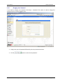
Master Controller Setting up Common Messages Common messages are an easy way to store and quickly send messages that are frequently used on the New Message screen. To add or edit the common messages, click Setup ‐> Common Messages. button to add a new common message. 1. Click the 2. Enter the text for the common message such as “Please call extension number:” and then press the button to save the changes. © JTECH Communications, Inc. Page 45 Master Controller 4.5
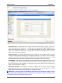
User Manual Advanced Message Settings To administer the global message settings, click Setup ‐> Messaging. Normal Beep Tone – Some devices such as pagers and Kirk wireless handsets support “beep tones” (sometimes also called “sub‐addresses” or “beep codes”). A typical pager supports beep codes A – D whilst a Kirk handset can support A – P. In summary these devices can provide different alerting patterns for each different beep code. The beep code selected in this field will be sent to a device when a normal message is dispatched. Priority Beep Tone – The beep code selected in this field will be sent to a device when a priority message is being dispatched. Messages can be flagged as a priority in a number of ways. Some input protocols such as scope or email include priority information. The New Message screen has a Priority Message button that can be clicked so that manually sent messages can be sent as priority. Local ID Digits – Every recipient in the Master Controller database must be assigned a Local ID. This ID is a unique numeric code to distinguish recipients internally. Incoming messages normally contain local ID information so that messages can be routed to the correct recipient. This field adjusts the length of the local ID from 1 ‐9 digits. Maintenance Recipient – This field is to define a recipient that will receive special messages generated by the system such as gateway faults, communication errors and polling errors. The table below shows the events which cause maintenance messages to be sent. IMPORTANT: If a message comes into the Master Controller with no defined local id, then it will be sent to the maintenance recipient selected in this field. If no maintenance recipient is defined, system messages will be sent to the recipient with local ID 0. Page 46 © JTECH Communications, Inc. User Manual Master Controller Gateway Trigger Alarm Router When an Alarm Router unit stops responding to polling. When an Alarm Router unit starts responding to polling after not responding. Cisco Comp 1 Could not connect to Cisco Call Manager. Target recipient is not defined in Comp 1 advanced settings or the target recipient was deleted. Generic Interface Watchdog timer has expired. Kirk 500 Communication polling with Kirk has broken down. Reporting Service Communication polling with Kirk has been restored. Cannot connect to Reporting Server. Login refused by Reporting Service. Cellular Router SMS Message could not be sent (all retries exhausted). SIM card is not inserted within a Cellular Router. Invalid SMS with PDU. Site Name – This field is used to add a site name to the Web GUI. This is a useful feature for users as it confirms that they are logged into the correct system. The site name is displayed on the main login screen and in the bottom right hand corner once logged in. Messaging Language – Currently the Master Controller supports English and Swedish character sets. button. Once you are happy with all settings click the © JTECH Communications, Inc. Page 47 Master Controller 4.6
User Manual Updating the Master Controller’s Firmware Your dealer may send you a new firmware file at some stage. This is a way to easily upgrade the unit’s functionality without returning it to the factory. To manage this process, click Setup ‐> Firmware Update. 1. The firmware file will usually be a .cfw format file. If the file has been zipped or sent via email, extract or save the .cfw file to your desktop. 2. Click the Browse button and browse to the location of the saved file. 3. Click Upload. The file will be sent over the network to the Master Controller. This may take several minutes depending on the speed of the connection between your PC and the Master Controller unit. Page 48 © JTECH Communications, Inc. User Manual Master Controller 4. Once the file has finished transferring the following message will be displayed. Press OK to continue. 5. Press the Install button to write the new firmware to the Master Controller unit. 6. After the firmware has been successfully installed you must restart the Master Controller for the new firmware to be loaded. IMPORTANT: You may also need to clear your browsers cache in order for new pages to be displayed properly in your browser. © JTECH Communications, Inc. Page 49 Master Controller 4.7
User Manual Database Tools All of the Master Controller settings, including recipients, port information, gateway information and network information, are stored in a database. Once a system is configured and operating correctly it is a good idea to backup a database as part of the site’s data recovery plan. To manage this process, click Setup ‐> Backup/Restore. Making a backup of a database 1. Click the Make Backup button 2. You will be prompted for a location where to save the database file. 3. Save the file to somewhere on your PC ready for burning to a CD or other backup device. Restoring a database ▲ WARNING: Restoring a database clears all settings currently on the unit! 1. Click Browse to locate the database file you wish to install on the current Master Controller unit. 2. Click the Restore DB button. 3. A popup will be shown prompting to continue. Click OK and the system will restart. Page 50 © JTECH Communications, Inc. User Manual 4.8
Master Controller Display Unit Temperature This screen is a useful diagnostic tool used to remotely monitor the unit temperature. To view the current unit temperature, click Setup ‐> Temperature. © JTECH Communications, Inc. Page 51 Master Controller 4.9
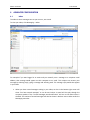
User Manual Port Communications Port communications is a very useful tool when troubleshooting gateways, ports or recipients. It is used to show incoming and outgoing data on a particular port. This is useful because it can be used to confirm that data is flowing to or from a port. To view Port Communications for a particular port, click Interfaces ‐> Ports. Now select the port that button next to it. needs to be monitored and click the A new window will open which will display incoming and outgoing data on the selected port. Page 52 © JTECH Communications, Inc. User Manual Master Controller To save the data that is currently shown on the screen to a file on your computer, click the button, followed by File ‐> Save As. and buttons. This is useful when the The display can be temporarily frozen using the trace window is showing large amounts of data and you need to pause the display to look through the data. NOTE: When the display is frozen by clicking the “Stop” button, data is still flowing through the port – it is only the display that is frozen. To clear the data shown in the window at any time, click the button. The ability to view communication data is also available for some gateways such as Kirk and Cisco. This is done by clicking button next to the gateway when viewing the Interfaces ‐> Gateways screen. It will not show protocol level data like the Port communications page does, however it is still useful diagnostic tool. © JTECH Communications, Inc. Page 53 Master Controller 4.10
User Manual System Log The System Log shows very detailed information about the Master Controller such as all messages processed, when users log on/off, when a gateway goes up/down or when certain settings are changed such as IP Settings. The System Log screen shows the same information as that which is sent out to a syslog server (see the syslog section on the Interfaces ‐> IP Setup page discussed previously in this manual). However the advantage is the system log screen requires no syslog server to be configured. The disadvantage is system log is cleared whenever the Master Controller is turned off. To view the system log, click Setup ‐> Display Log. Page 54 © JTECH Communications, Inc. User Manual 4.11
Master Controller Support Contact Information If you are a dealer, you may enter your own company contact details into the Master Controller so that end users can contact you directly if they have an issue or question. © JTECH Communications, Inc. Page 55 Master Controller User Manual To enable this menu item and edit the details, login to the Master Controller unit with login:dealer pass:dealerdata. The screen shown below will then be shown. Simply enter all of you contact details, tick the Show Dealer Page tick box and click Save. To prevent unauthorized access to these details, you can change the password. When finished click the Logout button. Page 56 © JTECH Communications, Inc. User Manual 4.12
Master Controller PDA, Cell /Mobile Phone Client The Master Controller web interface can detect if a compact browser is connecting to such as those used on mobile phones and PDA’s. In this case the Master Controller will display a cut down version of its web interface. After you have logged in with your normal login and password, you will have the following six options: •
Send Message – Send a message to a contact or group •
Inbox (0/0) – View messages that have been sent to you •
Sent Items – View sent messages and their status •
Active Alarms (0/0) – Active alarms can be viewed or cleared •
User Password – Change your password •
Logout – Exit the system or login as a different user The PDA/Mobile phone client does not use frames so that browsers from mobile phones and PDA’s that do not use frames are able to view the pages properly. Currently the three supported user agents are: •
Windows CE •
Symbian OS •
Apple iPhone © JTECH Communications, Inc. Page 57 Master Controller 5
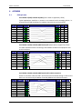
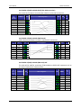
User Manual GATEWAY CONFIGURATION EXAMPLES The following section has some example system configurations which you may find useful information when setting up your own system. NOTE: Because of the nature of setting up gateways, you should configure any “output” gateways first, followed by any “input” or 2‐way (input + output) gateways. To administer gateways, click Interfaces ‐> Gateways. Page 58 © JTECH Communications, Inc. User Manual 5.1
Master Controller SMTP (email) In this example, we will setup a system which will can send and receive email messages and route appropriately. 5.1.1
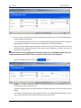
Master Controller Settings 1. The Master Controller unit will need to have an “Email” license key installed. Contact your place of purchase for this type of license key. 2. A Port for the email in gateway does not need to be configured. NOTE: Internet based messaging protocols like WCTP, SNPP, Cisco, Kirk 600/6000, SMTP (email), are implemented directly upon TCP/IP sockets, and thus do require a port to be configured. 3. An email gateway will need to be created. To add a new gateway, click the button. 4. Give the gateway a useful name and select Email in the Type drop down box. 5. The Character Set field determines the character set used when sending Email messages. For more details on language support and code page settings contact your dealer or JTECH. If in doubt please use the default character set (UTF‐8). 6. Choose Yes for the Input Gateway and Output Gateway options. If you are only sending or receiving emails, select the appropriate option. © JTECH Communications, Inc. Page 59 Master Controller User Manual 7. The Max Length, Split and Max Count options are very useful options to control outgoing email message length. Max Length – This setting refers to the maximum number of characters that an outgoing email message will be limited to. Use 0 for unlimited. Split – If an outgoing email is greater than the Max Length setting, you can select Yes to split the message up into multiple messages. Select No to send out only one message no matter what the message length. Max Count – If you selected Yes to the Split option, you can enter the maximum number of separate messages that will be dispatched. Use 0 for unlimited. 8. If the gateway is setup as an input gateway, you will see two extra fields named Local ID Lookup and Send Via. These settings determine the how a valid incoming message is routed out of the Master Controller. In the Send Via drop down box, select the gateway you wish the incoming email to be sent out of. Set Local ID Lookup to Yes if the incoming email should be scanned for a local ID so that the message can be delivered to the appropriate person. If this is set to No, Master Controller will assume that the incoming message contains the actual address of the recipient such as an email address, pager cap code, cell phone number etc. 9. When setting up this gateway, advanced details will need to be configured. Click the Advanced Settings button to administer these options. Page 60 © JTECH Communications, Inc. User Manual Master Controller 10. The Domain field refers to the domain that the email gateway will be working with. In the example above, if Master Controller dispatches an email to some recipient the email will appear from <message id>@TITAN.jtech.com. Emails sent to the Master Controller will need to be in the format <local id or recipient name>@ TITAN.jtech.com. 5.1.2
Master Controller Input Settings The Input Settings section will be visible if Input Gateway field was set to Yes on the previous screen. Size limit – This field can be used to limit the size of incoming emails. Emails containing more characters than the number in this field will be rejected. Default 200 characters. Ignore sender domain / Only accept from domains in list – For security purposes, Master Controller can be set to only accept emails from a known domain. In the example below, Master Controller would only accept incoming emails sent from “<anyone>@jtech.com”. Forward subject – Incoming emails may be sent to the Master Controller with text in the subject line. Select Yes here to accept this text and use it as part of the message. Forward body – Incoming emails may be sent to the Master Controller with text in the body. Select Yes here to accept this text and use it as part of the message. Forward sender – Incoming emails contain information about the sender. Select Yes here to accept this information and use it as part of the message. © JTECH Communications, Inc. Page 61 Master Controller 5.1.3
User Manual Master Controller Output Settings The Output Settings section will be visible if Output Gateway field was set to Yes on the previous screen. Subject format – When the Master Controller module sends an email message to a recipient, the actual message will appear in the body of the email. However this field is used to customize the subject line of the email as follows. Standard text can be entered that will appear in the subject for every outgoing message. Alternatively strings can be entered providing unique information for each email. •
%a ‐ the message's target address. •
%m ‐ the message text is inserted. •
%n ‐ product name. •
%t ‐ the type (0 for tone only, 1 numeric, 2 alpha, 3 email etc) is inserted as a digit. •
%p ‐ the priority (0 for normal, 1 for priority). •
%b ‐ the beep code (A through J) is inserted as a character. •
%s ‐ the sequence number of the message from this gateway. •
%u ‐ the user name that generated the message, otherwise "System". Use DNS to deliver email – If Yes is selected, email will be sent directly to the destination mail server, without the need of a relaying mail server. This is generally used when sending Email messages via a local Microsoft Exchange server. If No is selected, email will be sent to a relaying mail server. This is generally used when sending Email messages via an external mail server such as your ISP. You will need to configure the mail server name or IP address and a login/password. Click the Page 62 button to save all changes © JTECH Communications, Inc. User Manual 5.1.4
Master Controller Configuring an incoming Email System using Outlook Express Any device or PC capable of sending emails can be used to send Master Controller an email message. Once you have configured incoming email on the Master Controller you can test by following the directions below. Outlook is used as the e‐mail program in this example. Other e‐mail programs that support POP3 may be used. 1.
Open up Outlook Express (Start ‐> Programs ‐> Outlook Express) 2.
Select Tools ‐> Accounts ‐> Add ‐> Mail 3.
Enter a Display Name for this connection. 4.
In the Email Address field any address can be entered. This address will appear as the “Sender” to the Master Controller module. 5.
For the Incoming and Outgoing mail servers, enter the IP Address of the Master Controller unit. The Master Controller should be setup on a fixed IP Address. 6.
In the Account name field type any name and leave the Password field blank. 7.
Click Finish. 8.
Click the Create Mail button to create a new email message. 9.
The To field is used by Master Controller to determine where a message should be sent. The format of the address will depend on the Local ID Lookup field. Local ID Lookup = Yes If this field is set to Yes, emails sent to the Master Controller must be in this format. localid@domain © JTECH Communications, Inc. or recipientname@domain Page 63 Master Controller User Manual IMPORTANT: The domain must match that of the Domain field on the Email Gateway settings screen. For example, if a message was sent to Master Controller as follows, the unit would look in its database for a recipient named john and send the message to that person. Another example, if a message was sent to Master Controller as follows, the unit would look in its database for a Local ID of “3” and send the message to that person. Local ID Lookup = No If this field is set to No, emails sent to the Master Controller must be in this format. address@domain Page 64 © JTECH Communications, Inc. User Manual Master Controller IMPORTANT: The domain must match that of the Domain field on the Email Gateway settings screen. In this case the Send Via field becomes available. An outgoing gateway will need to be chosen which determines which gateway the message will be sent via. Therefore the address field will depend on the gateway chosen in the Send Via field. •
For an SMS gateway, the address will be a cell phone number. •
For an Email gateway, the address will be an email address. •
For a POCSAG gateway, the address will be a pager cap code. •
Or the address may be a Local ID which will be looked up by another system such as an SmartPage‐E unit. For example, if a message was sent to Master Controller with the Send Via option set to an SMS gateway, the unit will send the message to the cell phone number 90402567426. © JTECH Communications, Inc. Page 65 Master Controller 5.1.5
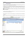
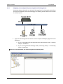
User Manual Configuring an incoming Email System using Microsoft Exchange Server Connecting a Master Controller to a Microsoft Exchange Server is also possible which allows for some more flexibility with Email messaging. The following section outlines how to setup an example system. 1. Login into the Exchange Server machine and run the System Manager program from the Start Menu. a. If you are using Microsoft Exchange 2003 Click Administrative Groups ‐> Routing Groups ‐> Connectors. b. If you are using Microsoft Exchange 2000, click Routing Groups ‐> First Routing Group ‐> Connectors. NOTE: In the example below, we will be using Microsoft Exchange 2003. Page 66 © JTECH Communications, Inc. User Manual Master Controller 2. Right click on the Connectors folder and select New ‐> SMTP Connector. 3. On the General tab, select Forward all mail through this connector to the following smart hosts field and then type the IP address of the Master Controller unit in square brackets as shown below. 4. In the Local Bridgeheads section, select the Microsoft Exchange email server that normal email messages are sent to on the network. © JTECH Communications, Inc. Page 67 Master Controller User Manual 5. Go to the Address Space tab. Click Add ‐> SMTP ‐> OK. 6. The information in the Address field shown below must match that of the Email Domain field described in the Master Controllers Email Gateway settings screen. 7. This will allow all emails sent to the @TITAN.jtech.com domain to be automatically forwarded and processed by the Master Controller. 8. Click OK to save the configuration and return to the Exchange System Manager. 9. The settings can now be tested in the same way as described in the previous section discussing Outlook Express. Page 68 © JTECH Communications, Inc. User Manual 5.2
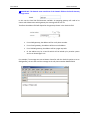
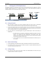
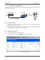
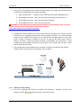
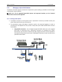
Master Controller System with Alarm Inputs (Connected to an Alarm Router) The Master Controller can be connected to a TITAN Alarm Router for management of alarm inputs. This allows any device to be monitored which can close/open switch contacts or provide a voltage change when an action occurs. A message can be dispatched to a recipient with a delay or escalation if required. Se
Setting up the System 1. The Master Controller unit will need to have an “Alarm Router” license key installed. Contact your place of purchase for this type of license key. In most cases, the Alarm Router itself will not require a license key as it will be operating in RS485 polled mode. 2. Firstly the units need to be connected using their RS485 ports. Run a blue straight‐through RJ45‐
RJ45 cable between COM1 on the Alarm Router and COM4 on the Master Controller. 3. Wire up the alarm inputs and power as described in the Alarm Router User Manual. 4. The RS485 ID and Baud rate must be set on the Alarm Router. Set the baud rate to be 9600bps and the RS485 ID to be 01. 5. Additional Alarm Router units can be added to the system simply by running a blue straight‐
through RJ45‐RJ45 cable between COM1 on the first Alarm Router and COM1 on the next Alarm Router. Each Alarm Router contains two physical RS485 connectors allowing extra units to be daisy chained. On any extra Alarm Router, the Baud rate must also be 9600bps and the RS485 ID must be unique. 5.2.1
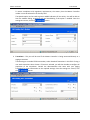
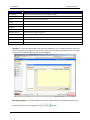
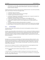
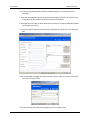
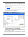
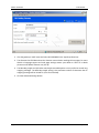
Master Controller Settings 1. The Port that the Alarm Router will be using must be configured. Since the Alarm Router operates over RS485, Com4 is the only port that can be used with an Alarm Router system. 2. Click Interfaces ‐> Ports and click the link next to Com4. These settings can normally be left to default as shown below. Make sure the RS‐485 field is set to Yes. © JTECH Communications, Inc. Page 69 Master Controller User Manual 3. Click the button to save all changes and return to the previous screen. 4. A gateway will now need to be created. Click Interfaces ‐> Gateways. To add a new gateway, click the button and this screen will be shown. 5. Give the gateway a useful name and select Alarm Router in the Type drop down box. 6. Select Com4 (RS485) in the Port drop down box. 7. Click the button to save all changes. 8. Next we need to configure the individual alarm settings. Click Interfaces ‐> Alarm Settings followed by the button. In this example we will configure alarm input #1 on an Alarm Router with RS485 ID #03. The alarm input will be connected to switch on a freezer door to alert someone if the door is accidentally left open for more than 60 seconds. Page 70 © JTECH Communications, Inc. User Manual Master Controller Name – Here you can give the alarm a unique name. Unit ID & Input – This field is how Master Controller knows which alarm it is currently configuring. The first digit denotes the RS485 ID of the Alarm Router with this alarm. The second digit is the alarm input (1‐16). Type – Choose one of the following options for the type of alarm. •
Alarm: Select this option if management of an alarm is required in both states (active and inactive). When an external input is active, the internal alarm state becomes active and an activation message can be sent. When external input is reset, internal alarm state becomes reset and a reset message can be sent. This type of alarm will be visible in the Active Alerts screen. •
Momentary: Select this option if an alarm message needs to be generated when an external input is activated. No internal alarm state is maintained therefore no reset message can be sent for this type of alarm. This type of alarm will not be added to the Active Alerts screen. •
Latching: An alarm set to be latching will remain active even after its electrical state has reset. A latched alarm can only be reset by the activation of another external alarm input that has been designated as a “Latch Reset” or “Global Latch Reset”. •
Latch Reset: Specifies that the selected external input will reset a latched input. The latched input is selected in the “Latch Reset Alarm” field. •
Global Latch Reset: Specifies that the selected external input will reset any other inputs that may be latched at that time. IMPORTANT: Some of the following options will not be available, depending on the option selected in the Type field. © JTECH Communications, Inc. Page 71 Master Controller User Manual Delay – The electrical state of the input must persist for this number of seconds before the alarm is activated. Activation delays can be 0 – 65535 seconds (approximately 18 hours) Activation Type – The activation type must be selected from one of these three options: •
Normally Open: An alarm will initiate when the contacts are closed (dry) or a voltage applied (opto) on the relevant input contacts. •
Normally Closed: An alarm will initiate when the contacts are opened (dry) or the voltage removed (opto) on the relevant input contacts. •
State Change: An alarm will occur every time the input state transitions from one state to another i.e. opened to closed or closed to opened (dry), or upon a voltage transition (opto). Recipient – Click or escalation. to choose the recipient for this alarm. The recipient may be a contact, user Active Message – The text in this field will be sent to the chosen recipient if the alarm is activated. Priority – Choose Yes to send the message as a priority over other messages. Reset Message – The text in this field will be sent to the chosen recipient if the alarm is reset. Allow Recipient To Clear Alarm – The Master Controller can interface with wireless telephony systems such as Kirk, Spectralink and Cisco. If an alarm message is sent to one of these handsets, the user has the ability to clear or ‘acknowledge’ the alarm. Select Yes in this field to enable this feature, otherwise alarms can only be manually cleared on the Active Alarms screen. NOTE: Due to the interaction between certain alarm settings, some combinations are not permitted to be saved to the Alarm Router. These restrictions prevent undesired operation such as not being able to reset alarms or allowing the unit to perform other illogical operations. The table below lists which settings are allowed to co‐exist on any single alarm input. Send resets State change Normally open Normally closed Latching Reset Latched Alarms N/A Momentary N/A Global Latch Reset N/A Alarm Page 72 © JTECH Communications, Inc. User Manual 9. Once you have finished configuring the alarm input, click the changes and return to the main screen Master Controller button to save 10. To view the currently active alarms, click Messaging ‐> Active Alerts. This window will automatically refresh keeping the status up to date. © JTECH Communications, Inc. Page 73 Master Controller User Manual 11. An alarm can be manually cleared (acknowledged) by selecting the alarm and then clicking the button. link is a useful option as it allows the Active Alerts Screen to be 12. The detached. If you have a dual monitor setup the detached window can be maximized on one screen while other programs can be opened in the other screen. Page 74 © JTECH Communications, Inc. User Manual 5.3
Master Controller PBX Paging with a TITAN Telephone Router Your Master Controller can seamlessly connect to the TITAN Telephone Router for paging over a PBX or standard analogue telephone line. The Master Controller will act as the master whilst any number of Telephone Routers can be connected to the system as slaves. 5.3.1
Setting up the System 1. Both the Master Controller unit and the Telephone Router will need to have a “distributed mode” license key installed. Contact your place of purchase for this type of license key. 2. Consult the Telephone Router user manual for details on how to set up each unit for distributed mode. The most important point is that the IP Address of the Master Controller must be entered into the Telephone Routers in its Distributed Mode Menu. 3. The units need to be connected together using their Ethernet ports. There are two ways to achieve this: i. Put both devices on a network or LAN using a network hub, switch or over the Internet. This method will make configuration and expansion easier. Note however your network administrator will have to ensure that firewall rules allow communication between the two units. ii. Use the supplied red cross‐over RJ45‐RJ45 cable between the Ethernet port on each module 5.3.2
Master Controller Settings 1. A port or gateway is not required to be setup in the Master Controller for this type of system. 2. The Telephone Router simply queries the Master Controller’s recipient database (master) over the network during each step of a call. 5.3.3
Sending a Message 1. The system will now need to be tested. Consult the documentation that came with your Telephone Router for details on operation. © JTECH Communications, Inc. Page 75 Master Controller 5.4
User Manual Configuring a Generic Gateway The Generic Interface gateway is an extremely flexible method of passing messages from external systems into the Master Controller. Typical applications include sending fire alarm panel alerts through to pagers and Nurse‐call events through to wireless handsets. Basically any simple (or not so simple!) incoming text alert event can be accepted by the Generic gateway and passed out to a multitude of devices and destinations as a text message. Text events and strings can be received by either a wired serial port or by a TCP IP connection. The core of the Generic Interface gateway is the scan string. The scan string determines the portions of the incoming text event that are considered to be important or relevant to route the message to a recipient. An incoming event may contain the actual message text, information about who is to receive the text or possibly just keywords that can be used to determine the recipient. The scan string is made up of a sequence of commands that can be built up to define the action to be taken upon receipt of a valid message. A command may be a Length command, an Until command, or a Match command. A Length Command is of the form Type*Digit(s), an Until Command is of the form Type^Expression, and a Match Command is of the form M=Term(s). The Generic Interface is very flexible, and consequently, the scan string can be quite complex. With experience, the scan string may be configured to accept particularly sophisticated messages. Type (used in Length and Until Commands) may be one of the following: • ? denotes “Ignore” • m denotes “Include in message” • p denotes “Local ID” • P denotes “Capcode” • i denotes “Alarm ID (not included in message)” • I denotes “Alarm ID (included in message)” • b denotes “Beep Code” Expression (used in Until Commands) may be one of the following: • k denotes “Keyword” (not included in message) • K denotes “Keyword” (included in message) • @ denotes “Delimiter” • Term Term (used in Expressions and Match Commands) refers to a standard string of one or more characters, and is made up of the following: • Characters not reserved for special meanings (those shown above) may also be used as expressions. If you wish to use one of the characters defined above as expressions, precede these characters with a backslash (\). Page 76 © JTECH Communications, Inc. User Manual •
Master Controller # followed by one to three digits, representing the decimal ASCII code of the character. Please note that this syntax may also be used in the Start Delimiter, End Delimiter and Separated By fields for the Generic Gateway. Conditional expressions may also be used by enclosing multiple expressions in curly braces separated by spaces. Some examples of valid commands appear below: • ?*12 denotes “Ignore 12 characters” • m*6 denotes “Include the next 6 characters in the message” • ?^k denotes “Ignore until keyword is received” • m^K denotes “Message test is anything (after start delimiter) until a keyword is received” and the keyword is to be included in the message. • m^@ denotes “Include all characters until a delimiter in the message to be sent” • ?^{ X Y Z } denotes “Ignore all characters until either an X, Y or Z character is received” • m^#13 denotes “Include all characters in the message to be sent until ASCII character 13 is received” • ?^\p denotes “Ignore all characters until the character ‘p’ is received” • p*4 denotes “The next four characters will define the Local ID of the recipient for this message” • M=Nurse denotes “If the next part of the string is not ‘Nurse’, then do not page send message” 5.4.1
Fire Panel Example The easiest way to explain the functionality of the Generic Interface gateway is perhaps to look at an example text string. Consider a system that possibly just alerts when there is a fire in a certain part of a building. Perhaps the system is capable of delivering text out of a serial port at 1200 baud, 8 data bits, no parity and 1 stop bit. The contents of the text string may simply be a pre‐programmed location name and the word “FIRE” possibly terminated by a carriage return (CR). Connecting its output to a dumb terminal may result in an output something like: 2007‐08‐01 13:21 Main Hall FIRE<CR> So we get the current date and time followed by the location and the word FIRE terminated by a <CR>. One of the first steps with Generic in is to determine what kind of information needs to be sent to the recipient and which recipient needs to receive the information. Another consideration is if the event should trigger an alarm or just a one off message (“send and forget”). See the hints at the end of this section for more information. Assume that the TITAN Master Controller is already configured with some output gateways and that there are some contacts created and working for messages to be sent to. The scan string required to pass the above message through to a recipient would be as follows: m^K?^@ In words this means ‘The message text includes everything up until the keyword, and the keyword is included in the message (Upper case K). Then ignore anything until the end delimiter. The message text sent to the recipient will be as follows: © JTECH Communications, Inc. Page 77 Master Controller User Manual 2007‐08‐01 13:21 Main Hall FIRE If the user just wanted the message text without the date and time, the following scan string could be used: ?*16m^K?^@ This would ignore the first 16 characters and then send through the remaining portion of the text including the keyword, i.e. Main Hall FIRE 5.4.2 More Examples Assume end delimiter of #13 in all cases Incoming string 666 FIRE Room1 East Wing <CR> Scan String p*3m^@ End Result FIRE Room1 East Wing sent to localID 666 Incoming string FIRE Room1 East Wing <CR> Scan String ?^Km^@ End Result FIRE Room1 East Wing sent to whatever contact is setup against the keyword FIRE 5.4.3
Real World Example 1. Check the Port settings match that of the external system. (baud rate etc) 2. Create the Generic Interface Gateway 3. If you are using the incoming string to directly address a local ID (“p” option in scan string) then there is no need to create alarms and keywords. Page 78 © JTECH Communications, Inc. User Manual Master Controller 4. This scan string shown below will directly address recipients, no need for alarms or keywords 5. If you are not using the incoming string to directly address a local ID (“p” option in scan string) then you will need to create some alarms and keywords 6. Keywords are tied to alarms which determine the action or recipient. Multiple keywords can be tied to one alarm. 7. This scan string will wait for a keyword then include the rest of the line as the message text. 8. The keyword fire will trigger the alarm called “fire alarm” which will raise an alarm and sent to the recipient listed. 9. The alarm will be raised and the message sent to the recipient listed. © JTECH Communications, Inc. Page 79 Master Controller User Manual •
•
•
10. This screen has several sections which will be described in more detail below. Name ‐ Give each alarm a unique name. Identifier ‐ The alarm identifier is used in conjunction with the scripting interface to identify alarms. Type ‐ A generic text event can cause various actions. o Momentary: Send a message – no alarm raised o Alarm: Activate an alarm. Optionally send a message to a recipient. Alarm can be reset manually (from GUI) or via 2‐way messaging o Latching: Activate an alarm. Optionally send a message to a recipient. Alarm can be reset manually (from GUI), via 2‐way messaging or by a Latch Reset event. o Latch Reset: Reset selected latched alarms (configurable) o Global Latch Reset: Reset all active LATCHING alarms that are active against this gateway NOTE: All alarms are by definition latching and must be cleared by some method. A latching alarm in Master Controller is essentially the same as an Alarm except that is has the capability of being reset by another generic event. A standard Alarm cannot be reset by another generic event and must be cleared by one of the 2 methods listed above. • Recipient ‐ Select the contact that will receive the alarm message • Priority ‐ Select if message is high importance • Reset Message ‐ A message will be sent to the same contact when the alarm is reset. • Allow Recipient to Clear Alarm ‐ If this alarm triggers a message to a 2‐way capable device (i.e. DECT or WiFi phone) then that recipient then has the option of clearing the alarm. Page 80 © JTECH Communications, Inc. User Manual 5.4.4
•
•
•
Master Controller Generic Interface Hints When entering non‐printing characters, enter as #nn (ASCII decimal values) i.e. a <CR> in the end delimiter field would be entered as #13 Keywords are processed in order, so in the below case the full keyword FIRE NOW EMERGENCY will trigger the top entry and FIRE NOW will trigger the lower entry. If the keywords are entered in the opposite order then the FIRE NOW keyword is triggered regardless of which string comes in via the input. Maybe useful for differentiating strings that have keywords at the end. The m type character can be used more than once. For example a scan string may be: ?*10m*3?*9m*7?^@ This would mean to ignore the first 10 characters in the incoming data, treat the next 3 as the message, ignore the next 9 characters then the next 7 are the remainder of the message. Ignore everything else until the end delimiter. The message text will therefore be the 3 characters and the 9 characters combined into one string. © JTECH Communications, Inc. Page 81 Master Controller 5.5
User Manual POCSAG Paging over IP The Master Controller can communicate with multiple TITAN products over a network such as a LAN or the Internet. One such product is the TITAN SmartPage‐E range of IP based POCSAG transmitters. This connected by an IP connection, sending messages to POCSAG pagers is possible. It also means that existing infrastructure can be utilized rather than the need for long distance custom wiring. 5.5.1
Setting up the System 1. The Master Controller unit will need to have a “TAP” license key installed. Contact your place of purchase for this type of license key. 2. The two units need to communicate over their Ethernet ports, which can be achieved in two ways: i. Put both devices on a network or LAN using a network hub, switch or over the Internet. This method will make configuration and expansion easier. Note however your network administrator will have to ensure that firewall rules allow communication between the two units. ii. Use the supplied red cross‐over RJ45‐RJ45 cable between the Ethernet port on each module 5.5.2
Master Controller Settings 1. The Port that the SmartPage‐E unit will be using must be configured. In this example we will use the TAP over IP protocol. 2. Click Interfaces ‐> Ports and click the link next to an unused IP port. 3. For this type of system, leave the Method field set to TCP. Page 82 © JTECH Communications, Inc. User Manual Master Controller 4. In the Bandwidth field, select the speed of the network connection between the SmartPage‐E and Master Controller unit. 5. The Port field must match that of the Port setting in the SmartPage‐E unit. Setting up the SmartPage‐E unit is discussed in the next section. 6. The remaining field, Listen on this Port, should be set to No since this is an outgoing TAP gateway only. 7. Click the button to save all changes and return to the previous screen. 8. A gateway will now need to be created. Click Interfaces ‐> Gateways. To add a new gateway, click the button and this screen will be shown. 9. Give the gateway a useful name and select TAP in the Type drop down box. 10. The Character Set field determines the character set used when sending TAP messages. For more details on language support and code page settings contact your dealer or JTECH. If in doubt please use the default character set (UTF‐8). 11. Master Controller needs to know which Port it will be using for communication with the SmartPage‐E. Using the drop down box, select the Port that you configured above. (IP1 in the example above) 12. The Input Gateway/Output Gateway option determines whether this gateway is used to accept or dispatch TAP messages. Either option can be selected but in this example the gateway will be functioning as an Output gateway. © JTECH Communications, Inc. Page 83 Master Controller User Manual 13. The Max Msg Length and Split when max length exceeded options are very useful to control long outgoing messages. The Max Msg Length setting is the maximum number of characters that an outgoing message will be limited to. (use 0 for unlimited). 14. The Master Controller needs to know the IP Address of the SmartPage‐E unit in order to communicate with it. The Address field is where this IP Address is entered. Setting up the SmartPage‐E unit is discussed in the next section. 15. Click the Advanced Settings button. 16. Some service providers will require a TAP password in order to send messages. SmartPage‐E does not use a password, so simply leave these fields blank. 17. Click the button to save all changes and return to the previous screen. 5.5.3
SmartPage‐E Settings 1. There are three important screens that must be setup on the SmartPage‐E unit in order for this system to operate. Firstly log into to your SmartPage‐E unit via its web interface. Remember the login credentials are username “maint” with no password. 2. Click the Network Settings menu. Turn off DHCP and give the unit a unique fixed IP Address on the network. This IP address will need to be entered in the gateway settings on the Master Controller. Page 84 © JTECH Communications, Inc. User Manual Master Controller 3. Click the Protocol menu. Make sure the Ethernet Protocol Use is set to TAP. 4. There are two ways of setting up messaging with this type of system. i.
In the TITAN SmartPage‐E, tick Lookup Pager ID – This means that the address for each recipient in the Master Controller must be a Local ID. SmartPage‐E will look up the Local ID in its internal database and determine the cap code that it should be sending this message to. For example, the recipient in the Master Controller below is address 1. © JTECH Communications, Inc. Page 85 Master Controller User Manual The SmartPage‐E will look up its internal pager database and determine that it should be send the message to cap code 16. Page 86 © JTECH Communications, Inc. User Manual ii.
Master Controller In the TITAN SmartPage‐E, do not tick Lookup Pager ID ‐ Alternatively the Master Controller can be configured so that the address for each recipient in the Master Controller will be a cap code. For example, the recipient in the Master Controller below is address 16. SmartPage‐E will simply send the message straight out on the required cap code (16). This method is recommended as it allows all database configurations to stay in one place. (The Master Controller) © JTECH Communications, Inc. Page 87 Master Controller 5.5.4
User Manual Sending a Message 1. To test the new TAP over IP output gateway is working properly, you will need a pager with a known cap code. 2. The pagers baud rate (512/1200/2400bps) and will need to match that of the setting in SmartPage‐E on the POCSAG menu. 3. The frequency of the pager will also need to match that of the transmitter inside the SmartPage‐
E unit. 4. Create a new contact. Recipients ‐> Contacts ‐> Add New. 5. The Address field should contain the cap code of the test pager. In the Send via field, choose the TAP out via IP gateway that you created in the previous section. 6. Finally click the button. Type a test message and click Send. The pager should display the message you typed. If the pager does not receive the message, check important settings such as the baud rate, frequency and cap code. Page 88 © JTECH Communications, Inc. User Manual 5.6
Master Controller TAP Protocol using Dialup Modem The Master Controller can communicate with TAP SMS/Paging service providers and wide area pager carriers via its built in modem. 5.6.1
Setting up the System 1. The Master Controller unit will need to have a “TAP” license key installed. Contact your place of purchase for this type of license key. 2. Run a standard RJ12‐RJ12 phone cable from the Modem connector on the Master Controller to the analogue phone line that will be used for outgoing calls. 5.6.2
Master Controller Settings 1. First of all, the modem port must be configured. 2. Click Interfaces ‐> Ports and click the link next to the Modem Port. © JTECH Communications, Inc. Page 89 Master Controller User Manual 3. The Baud, Data bits, Parity and Stop bit fields can be left to their default settings as shown above. These settings determine the speed of connection between the Master Controller hardware and its internal modem. 4. To comply with local telecommunication regulations, you must select the Country where the Master Controller unit is situated. 5. The Master Controller contains a speaker on board which can be used to provide an audible indication of dial tones and handshaking during calls. Select Off to disable sounds. 6. Click the button to save all changes and return to the previous screen. 7. A gateway will now need to be created. Click Interfaces ‐> Gateways. To add a new gateway, click the button and this screen will be shown. 8. Give the gateway a useful name and select TAP in the Type drop down box. 9. The Character Set field determines the character set used when sending TAP messages. For more details on language support and code page settings contact your dealer or JTECH. If in doubt please use the default character set (UTF‐8). 10. Master Controller needs to know which Port it will be using for communication. Using the drop down box, select the Modem. Page 90 © JTECH Communications, Inc. User Manual Master Controller 11. The Input Gateway/Output Gateway option determines whether this gateway is used to accept or dispatch TAP messages. Either option can be selected but in this example the gateway will be functioning as an Output gateway. 12. The Max Msg Length and Split when max length exceeded options are very useful to control long outgoing messages. The Max Msg Length setting is the maximum number of characters that an outgoing message will be limited to. (use 0 for unlimited). 13. The Baud, Data bits, Parity and Stop bit fields determine the connection speed between the Master Controllers internal modem and the remote device that it is calling. The settings must match those used by the remote system. You should contact your carrier or service provider for these settings. 14. In the Phone Number field, enter the phone number of the remote system the Master Controller will be dialing. 15. Click the Advanced Settings button. 16. Some service providers will require a TAP password in order to send messages. Contact your carrier or service provider for this information. 17. Click the button to save all changes and return to the previous screen. 5.6.3
Sending a Message 1. Create a new contact. Recipients ‐> Contacts ‐> Add New. 2. There are two types of TAP service providers. a. Service providers used to send SMS to cell phones b. Service providers used to send text messages to wide area pagers 3. Depending on the receiving device, the Address field should contain the ID, cap code or cell phone number of the recipient you wish to contact. In the Send via field, choose the TAP out via Modem gateway that you created in the previous section. 4. Finally click the button. Type a test message and click Send. © JTECH Communications, Inc. Page 91 Master Controller 5.7
User Manual SMS (Short Message Service to Cell Phones using Cellular Router) In conjunction with a TITAN Cellular Router, Master Controller can send SMS messages directly to cell phones anywhere in the world. The system can also receive SMS and route these messages out to the required recipients pager, email or wireless telephony handset. 5.7.1
Setting up the System 1. The Master Controller unit will need to have a “Cellular Router” license key installed. Contact your place of purchase for this type of license key. 2. The two units need to be connected using a straight through RJ45‐RJ45 cable such as the supplied blue cable. Connect the Com1 on the TITAN Cellular Router to a spare Com port on the TITAN Master Controller. 5.7.2
Master Controller Settings 1. First of all, the Com port must be configured. 2. Click Interfaces ‐> Ports and click the connected to. link next to the Com port the Cellular Router is Page 92 © JTECH Communications, Inc. User Manual Master Controller 3. The Baud, Data bits, Parity and Stop bit fields should be left to their default settings as shown above when connecting to a Cellular Router. These settings determine the speed of connection between the Master Controller and the external modem (Cellular Router). 4. Click the button to save all changes and return to the previous screen. 5. A gateway will now need to be created. Click Interfaces ‐> Gateways. To add a new gateway, click the button and this screen will be shown. 6. Give the gateway a useful name and select Cellular Router in the Type drop down box. 7. The Character Set field determines the character set used when sending SMS messages. For more details on language support and code page settings contact your dealer or JTECH. If in doubt please use the default character set (UTF‐8). 8. The Master Controller needs to know which Port it will be using for communication. Using the drop down box, select the Com port you configured above. 9. The Input Gateway/Output Gateway option determines whether this gateway is used to accept or dispatch SMS messages (or both). In this example select Yes for both. © JTECH Communications, Inc. Page 93 Master Controller User Manual 10. The Max Msg Length and Split when max length exceeded options are very useful to control long outgoing messages. The Max Msg Length setting is the maximum number of characters that an outgoing message will be limited to. (use 0 for unlimited). 11. If the gateway is setup as an input gateway, you will see two extra fields named Local ID Lookup and Send Via. These settings determine the how a valid incoming message is routed out of the Master Controller. This will be discussed in detail in the Receiving SMS section below. 12. Click the Advanced Settings button. 13. If you are using a third party cellular modem, it may require an Init String. If using the TITAN Cellular Router leave this field blank. 14. For security purposes, some SIM cards have a PIN which must be entered before messages can be sent. If the SIM you are using requires a PIN enter it in the GSM PIN field. 15. The Use 16 bit encoding (UCS2) field should be set to Yes if you are sending messages to international languages such as Chinese, Japanese, Korean etc. For English, this field can be left set to No and messages will 7 bit encoded. 16. The Validity field tells the SMS service provider how long to store a message before it is discarded, even if the message has not been read. 17. Click the button to save all changes and return to the previous screen. Page 94 © JTECH Communications, Inc. User Manual 5.7.3
Master Controller Sending SMS 1. Create a new contact. Recipients ‐> Contacts ‐> Add New. 2. In the Address field enter the cell phone number of the person you wish to contact. NOTE: Cell phone numbers can be in international format (leading “+”) 3. Select the SMS gateway in the Send Via drop down box. 4. Set Receiver Type to Email/Unfiltered. 5. Finally click the button. Type a test message and click Send. After a short time the message will appear on your cell phone. 5.7.4
Receiving SMS 1. In order for Master Controller to receive and process SMS messages, you must know the cell phone number of the SIM card installed in the Cellular Router. 2. The format for sending a message depends on the Local ID Lookup field in the gateway setting. a. Local ID Lookup = Yes – Setting this field to Yes means, incoming messages will be scanned for a Local ID. This allows messages to be sent out via any gateway. SMS messages sent to the Cellular Router should be in the following format. Local ID lookup 002 test will send the message “test” to the recipient with Local ID 2 © JTECH Communications, Inc. Page 95 Master Controller User Manual b. Local ID Lookup = No – Setting this field to No means incoming messages will be scanned for an Address. You will need to select the gateway that messages will be routed to using the Send Via field. This means that messages can only be sent out via one gateway. SMS messages sent to the Cellular Router will be in a different format depending on the selection in the Send Via field as follows. Send via SMS gateway 0414854657 test will send the message “test” to the cell phone number 0414854657 Send via Email gateway [email protected] test will send the message “test” to [email protected] Send via POCSAG gateway 0000008 test will send the message “test” to the pager with cap code 8 Send via gateway which uses Local ID to communicate with another system such as SmartPage‐E 002 test will send the message “test” to the recipient with Local ID 2 3. If an SMS messages is sent to a User, the message will appear in their Inbox when they log in to the web interface. 4. Incoming SMS messages that do not have an addressee (i.e. no prefix to indicate local ID) are sent to maintenance recipient first then local ID 0 if no maint. Page 96 © JTECH Communications, Inc. User Manual 5.8
Master Controller Messaging to Cisco System The Master Controller supports connection to Cisco Call Manager making it possible to send messages to Cisco wireless and wired handsets. NOTE: For a list of supported Call Manager or Unified Communications Manager versions and supported handsets, see the Technical Specifications section of the Appendix. 5.8.1
Setting up the System 1. The Master Controller unit will need to have a “Cisco” license key installed. Contact your place of purchase for this type of license key. 2. The Cisco system and Master Controller need to be connected together in order to communicate. Titan Master Controller
Server running
Cisco Call Manager
Ethernet
LAN / WAN / INTERNET
Wired Handsets
5.8.2
Wireless
Access
Points
Wireless Handsets
Master Controller Settings 1. First of all, a gateway will need to be created. Click Interfaces ‐> Gateways. To add a new gateway, click the © JTECH Communications, Inc. button and this screen will be shown. Page 97 Master Controller User Manual 2. Give the gateway a useful name and select Cisco in the Type drop down box. 3. The Character Set field determines the character set used when sending Cisco messages. For more details on language support and code page settings contact your dealer or JTECH. If in doubt please use the default character set (UTF‐8). 4. The Max Msg Length and Split when max length exceeded options are very useful to control long outgoing messages. The Max Msg Length setting is the maximum number of characters that an outgoing message will be limited to. (use 0 for unlimited). 5. Click the Advanced Settings button. Page 98 © JTECH Communications, Inc. User Manual Master Controller 6. This screen contains several mandatory fields which must be filled correctly for the system to operate. •
Service Name: The name of the inbox that will be shown in phone. •
Call Mgr Address: The IP address or computer name of the server hosting Cisco Call Manager. •
Call Mgr Port: The port that Cisco Call Manager uses to accept HTTPS requests. •
Call Mgr Auth: The authorization string that Call Manager requires, to be able to make an HTTP request. Usually consists in a string like "user:password" (without the quotes). •
Call Mgr Version: Select the version of Call Manager software you are using. •
Update Addr (min): This field adjusts how often the Master Controller polls Call Manager for the active device list and current IP addresses. This time should be reduced (i.e., 1 – 3 minutes) if the phones change IP addresses frequently or can roam from one WLAN to another. However reducing this time may cause message delays if there are hundreds or thousands of devices in the response from Call Manager. •
Phone Auth: Another authorization string required by the phone when Master Controller sends an HTTP request directly to it. Usually consists in a string like "user:password" (without the quotes). •
Requests Port: The port in which Master Controller will be listening for phone requests. •
Implements Messages button: The messaging service can be implemented either through the handsets "Messages" button or the "Services" button, this option establishes which of the services is being used. •
Prompt on new message: This option is used when a new message is sent to the handset. If "Yes" is selected a notification of a new message will be sent, if "No" is selected the actual message will be sent. •
Sound File: Name of the sound file that will be played when a message is sent (this file has to exist in the Cisco system FTP server). •
Show Accept Option: This option is used to display or not the "Accept" option in the handset when a message is sent. •
Show Clear Option: This option is used to display or not the "Clear" option in the handset when a message is sent. •
Show Escalate Option: This option is used to display or not the "Escalate" option in the handset when a message is sent. •
Msg Alert Policy: This option applies to messages sent directly to phones. That is, when a new message or a notification is sent to the phone this message will be shown in the phone taking into account the value of this field. •
Retries: Number of additional handset alert attempts that will be made, before indicating an error on any messages in the queue. •
Retry Timeout: Number of seconds since start of previous alert before re‐alert attempt. A new message to a handset will pre‐empt this. © JTECH Communications, Inc. Page 99 Master Controller •
User Manual Complete Timeout: Number of seconds after a message has been read that it will automatically be deleted from the handsets message queue, and the message system status set to Complete. 7. Click the button to save all changes and return to the previous screen. 5.8.3
System Operation •
When a message is sent to a handset, it may alert or play a sound depending on the gateway settings. •
The user will press the handsets “Messages” button where they will see the “TITAN Inbox”. The number in brackets after the TITAN Inbox refers to the number of unread messages. •
Once the user clicks the TITAN Inbox, they will see messages received by the handset. •
The icon next to each message shows whether a message is priority unread, unread, priority read or read. Messages are presented in this order first and if there are messages with the same status they are sorted by time received. •
By pressing the READ soft key the user will view the entire contents of the message. Depending on the gateway settings, the user will also have the ability to Callback, Escalate, Accept or Clear via the soft keys. NOTE: The force escalate and clear alarm functionality can be enabled/disabled on an individual basis when creating or editing a recipient. NOTE: The callback extension can be made up of the DTMF characters # and *. You can also use the , (comma) character to act as a 1 second pause. •
If the handset or user does not respond in a configured time by pressing the start key to read the message or if the handset if turned off, then the message will be marked as failed. 5.8.4
Sending a Message 1. Create a new contact. Recipients ‐> Contacts ‐> Add New. Page 100 © JTECH Communications, Inc. User Manual Master Controller 2. Give the contact a useful Name. 3. In the Address field enter the handset number of the handset for the person you wish to contact. The format is SEPxxxxxxxxxxxx and it is not case sensitive. 4. Select the Cisco gateway in the Send Via drop down box. 5. Finally click the button. Type a test message and click Send. After a short time the message will appear on the handset. © JTECH Communications, Inc. Page 101 Master Controller 5.9
User Manual Messaging to Kirk Wireless Server 600v3 System The Master Controller supports connection to Kirk 600v3 system making it possible to send messages to Kirk system handsets. NOTE: For a list of supported Kirk Systems and supported handsets, see the Technical Specifications section of the Appendix. 5.9.1
Setting up the System 1. The Master Controller unit will need to have a “Kirk 600/6000” license key installed. Contact your place of purchase for this type of license key. 2. The Kirk 600v3 unit needs some configuration before messaging will function. Connect the Eth1 port on the Kirk unit to your local network as shown below. 3. The default IP address of a KWS 600v3 system is 192.168.1.1 via the Eth1 port. The default password is user: admin, password: ip1200. 4. Attempt to browse to the Kirk system by typing the IP address of the unit. If the IP address is not known try 192.168.1.1 or 192.168.0.1. The PC you are trying to connect with will need to be on the same subnet as the Kirk system. If you do not know the IP address of the Kirk unit, you will need to reset the IP address back to default. NOTE: To reset the IP address of a Kirk 600v3, hold the reset button down for about 5 seconds, then release. The settings will be defaulted with DHCP enabled. Then press the reset button again briefly to get it to change IP to 192.168.0.1 Page 102 © JTECH Communications, Inc. User Manual Master Controller 5. Once you can successfully browse to the web interface page, some special commands need to be executed on the KWS 600v3 unit to enable messaging. a. Open a web browser (Replace 172.18.0.196 with the IP of your KWS 600v3 unit) b. At the address bar enter: http://172.18.0.196/!config change TELNET0 /port 23 c. At the address bar enter: http://172.18.0.196/!config write d. At the address bar enter: http://172.18.0.196/!reset ▲ WARNING: The Kirk 600v3 unit must have the latest firmware version installed in order to operate reliably. Firmware can be downloaded from Kirk Polycom directly: http://www.kirktelecom.com/Installer/suk198.asp 6. Configuration of the Kirk 600v3 unit is done via the Eth1 port, however later on we will be using the Eth0 port for messaging communication with the Master Controller. It is recommended to assign a static IP address to the Eth0 port, or setup the Ethernet MAC address in your DHCP server to assign a constant IP address to the unit. To setup the Kirk 600v3 with a static IP address, click Eth0 ‐> DHCP and change the Mode to be Disabled. Then click Eth0 ‐> IP and configure the static IP address settings. If you are a DHCP server instead, then click Eth0 ‐> DHCP and set the Mode to be Client. 7. Now configuration of the Kirk 600v3 unit is complete on the Eth1 port. Remove the network cable from Eth1 port and plug it into Eth0 port as shown below. 5.9.2
Master Controller Settings 1. First of all, a gateway will need to be created. Click Interfaces ‐> Gateways. To add a new gateway, click the © JTECH Communications, Inc. button and this screen will be shown. Page 103 Master Controller User Manual 2. Give the gateway a useful name and select Kirk 600/6000 in the Type drop down box. 3. The Character Set field determines the character set used when sending Kirk messages. For more details on language support and code page settings contact your dealer or JTECH. If in doubt please use the default character set (UTF‐8). 4. The Max Msg Length and Split when max length exceeded options are very useful to control long outgoing messages. The Max Msg Length setting is the maximum number of characters that an outgoing message will be limited to. (use 0 for unlimited). 5. Click the Advanced Settings button. Page 104 © JTECH Communications, Inc. User Manual Master Controller Long Message Format – The Long Message Format field sets the mode of operation of messaging to Kirk DECT handsets. When disabled, the message will be sent directly to the handset, but will be discarded if the handset receives another message or is used for a voice call. When enabled, handsets will be alerted with a new message notification, and may then scroll through the message. No further messages will be received until this message is cleared from the handset. When the Long message option is set to Yes, extended functionality is available: •
If the string “Ext:xxx” is found in the message text, the phone number field is set in the message sent to the handset, with the xxx being the phone number. This means that the user simply needs to press the dial key and this phone number or extension will be dialed (see below). NOTE: The extension can be made up of the DTMF characters # and *. You can also use the , character to act as a one second pause. •
When a message is sent to the Kirk handset, the user is prompted with “New Message Press Tick”. •
User presses tick. A session (MSF) is established with the handset, and the first page of the message is sent to the handset (If the message is longer than can display on the screen). © JTECH Communications, Inc. Page 105 Master Controller User Manual •
If handset or user does not respond in time (by pressing the tick key to read the message) or is out of range, then the message is marked as failed. •
After pressing the tick key, the user can scroll through the message. •
Press key ‘1’ to acknowledge the call is being handled. Message is marked as Acknowledged & Read. •
Press key ‘2’ to cancel the alarm that generated this message. If there was no alarm then key input is ignored. Message is marked as Read if not already. NOTE: This functionality can be enabled/disabled on a per recipient basis or globally in the Kirk Gateway Advanced settings section. •
Press key ‘3’ to immediately force escalate to the next recipient in the escalation. If there is no escalation or if forced escalation is not allowed, nothing happens. NOTE: This functionality can be enabled/disabled on a per recipient basis or globally in the Kirk Gateway Advanced settings section. •
Press Dial to dial the call‐back number that was embedded in the message with the string Ext:xxx. Message Service Format – The MSF II option enables tones that are available with newer Kirk DECT handsets and base stations. For older Kirk products this must be set to MSF I. Tone ID A / I B / J C / K D / L E / M F / N G / O H / P MSF I Description Pattern 2 (Tone 9 in PP) Pattern 3 (Tone 6 in PP) Pattern 4 (Tone 7 in PP) Pattern 5 (KeyBeep in PP) Pattern 6 (KeyClick in PP) Pattern 7 (Accept Tone in PP) Vibrate Silence Tone ID A B C D E F G H I J K L M N O P MSF II Description Tone 1 in PP Tone 2 in PP Tone 3 in PP Tone 4 in PP Tone 5 in PP Tone 6 in PP Tone 7 in PP Tone 8 in PP Tone 9 in PP Vibrate/Tone 1 in PP Vibrate/Tone 2 in PP Vibrate/Tone 3 in PP Vibrate/Tone 9 in PP Vibrate Tone in PP Use Tone Preset in PP Press Tick to Stop Alert Save in Handset (SIS) – Setting this field to Yes will allow short messages to be stored in the handset for later retrieval via the Kirk Inbox. Page 106 © JTECH Communications, Inc. User Manual Master Controller Alerting Pattern – If MSFII is selected, the alert pattern for messages can be adjusted between Continuous, Internal, External and Alarm. Priority Alerting Pattern – If MSFII is selected, the alert pattern for priority messages can be adjusted between Continuous, Internal, External and Alarm. Alert Timeout (secs) – This option is only active when MSFII used and will only have effect if Beep Tones A ‐ O are used. It allows you to adjust the length of the alert when a message is received by the handset, between 1 ‐ 255 seconds. Display Timeout (secs, SIS only) – This will determine how long the message will be displayed on the handset screen before reverting back to normal. This option is only valid if SIS is checked. Format Message For Handset – This field prevents words from being split across multiple lines on the 30xx and 40xx Kirk handsets. Setting this field to Yes will optimize word wrapping for a 12 x 3 display, keeping whole words intact and using spaces to optimize word positioning. This option should be set to No if you are using 50xx Kirk handsets as those handsets provide their own word wrapping local to the handset. NOTE: When word wrapping is turned on, the message number and "]" character are not displayed at the beginning of the message. Prompt for Start – If this field is set to Yes, when the message receives a message it will prompt to press the Start or Tick button to show the message. Otherwise it will just show the message. Allow Forced Escalation – As discussed above in the Long Message Format section, the Kirk phone user has the ability to force escalate using keys on the handset. The functionality can be enabled or disabled using this field. This setting applied to all messages coming into the Kirk gateway and would override all individual contact settings if set to No. Allow Manual Alarm Control – As discussed above in the Long Message Format section, the Kirk phone user has the ability to clear alarms using keys on the handset. The functionality can be enabled or disabled using this field. This setting applied to all messages coming into the Kirk gateway and would override all individual contact settings if set to No. Failed Attempt Retries – This refers to the number of times the Master Controller will attempt to send the message to the handset before indicating the message as failed. Time Between Retries – The time (seconds) between retries. Session Timeout – When viewing messages, this field refers to the time (seconds) the Master Controller will wait for a key press before timing out. Ack Session Timeout – The number of seconds to wait for a key press while handset is in an MSF session and user has acknowledged the message by pressing 2 or 3. Session will be terminated by the application. Handset will return to standby. Complete Timeout – Number of seconds after a message has been read that it will automatically deleted from the handsets message queue. And the message system status set to Complete. This only occurs if handset is not displaying messages (standby). Kirk CCFP IP – Enter the IP Address of the KWS 600v3 system here. © JTECH Communications, Inc. Page 107 Master Controller User Manual Kirk CCFP Type – Choose Kirk 600v3 in this field. If you had a Kirk 6000 system you would choose Kirk 6000 here instead. Essentially the interfaces are the same except the Kirk 6000 uses a different port (56003 as opposed to 23). CCFP Auth User Name – Enter the User Name for the KWS 600v3 system in this field. These are the same login details as used to login to the KWS 600v3 web configuration interface. (default username “admin”) CCFP Auth Password – Enter the Password for the KWS 600v3 system in this field. These are the same login details as used to login to the KWS 600v3 web configuration interface. (default password “ip1200”) COBS Duress Recipient – The KWS 600v3 system is compatible with the duress button on the 4000 series handsets. When this button is pressed a message can be generated and sent to the contact setup in the Recipient field COBS Duress Message – The text in the Message field will be appended to the handset name. For example let’s assume a user “Bob” has been setup to receive all duress messages and the word “Panic” has been entered into the Message field. When the duress button is pressed on Kirk handset 12, Bob will receive the message “Handset 12: Panic”. Use DECT Location – This feature applies to 4040 handsets only. When the alarm button is pressed on the top of the 4040 handsets, they send the location of their 5 closest base stations with the alarm duress information. The ID of the base stations can be looked up to enhance messages generated from these alarms. (See the Edit DECT Locations option below) Use LF Location (COBS only) – This feature applies to COBS handsets only. When an alarm is generated on the COBS handsets (alarm button, tilt sensor, pull cord), they send through their RF location and the alarm type. The ID of the LF beacons can be looked up to enhance messages generated from these alarms. (See the Edit LF Locations option below) Edit DECT Locations – This option allows configuration of the DECT base station lookup table to provide descriptions for each beacon. This interface shall support 20 beacons (00 ‐ 19) each with a maximum of 20 characters. Page 108 © JTECH Communications, Inc. User Manual Master Controller Edit LF Locations – This option allows the editing of the LF Location lookup table to provide descriptions for each beacon. This interface shall support 1025 beacons (0000 ‐ 1024) each with a maximum of 20 characters. The button shall be disabled if the Edit LF Location configuration is turned off. 6. Click the © JTECH Communications, Inc. button to save all changes and return to the previous screen. Page 109 Master Controller 5.9.3
User Manual Sending a Message 1. Ensure all handsets are registered and logged onto the Kirk 600v3 system. This process is normally done by the Kirk system administrator. Each user setup in the Kirk system has a “number” assigned. 2. This number can be viewed in the Kirk web interface. Open your web browser and type the IP address that you configured for Eth0 previously. Under the Administration menu, click Dect ‐> Users ‐> Show and the following screen will be shown. 3. For example the number for Johns Phone is 15. 4. Create a new contact. Recipients ‐> Contacts ‐> Add New. Page 110 © JTECH Communications, Inc. User Manual Master Controller 5. Give the contact a useful Name. 6. In the Address field enter the handset number for the person you wish to contact. In the example above you would type “15” here. 7. Select the Kirk gateway in the Send Via drop down box. 8. Finally click the button. Type a test message and click Send. After a short time the message will appear on the handset. © JTECH Communications, Inc. Page 111 Master Controller 5.10
User Manual Messaging to Kirk 500 and 1500 Systems The Master Controller supports connection to the Kirk WTS 500 and WTS 1500 systems making it possible to send messages to Kirk DECT system handsets. NOTE: For a list of supported Kirk Systems and supported handsets, see the Technical Specifications section of the Appendix. 5.10.1 Setting up the System 1. The Master Controller unit will need to have a “Kirk 500/1500” license key installed. Contact your place of purchase for this type of license key. 2. The Kirk system and Master Controller need to be connected together in order to communicate. This depends on the type of Kirk system being used a. Kirk WTS 1500 ‐ Use a straight through RJ45‐RJ45 cable such as the supplied blue cable in conjunction with a Kirk connector set (available from JTECH). Alternatively you can make a custom serial cable using the pin outs from the appendix in this manual. Connect from a Com port on the TITAN Master Controller to the Com port on the WTS 1500 system. b. Kirk WTS 500 – A custom made serial cable needs to be created for this purpose. See the appendix in this manual for pin out information. Connect from a Com port on the TITAN Master Controller to the Com port on the WTS 500 system. Page 112 © JTECH Communications, Inc. User Manual Master Controller Repeater (8 max)
Kirk Wireless
Handsets
Titan Master Controller
COM1
Kirk WTS 500
Custom Cable – see appendix
(Supplied grey cable)
Repeater
5.10.2 Master Controller Settings 1. First of all, a gateway will need to be created. Click Interfaces ‐> Gateways. To add a new gateway, click the button and this screen will be shown. 2. Give the gateway a useful name and select Kirk 500/1500 in the Type drop down box. 3. The Character Set field determines the character set used when sending Kirk messages. For more details on language support and code page settings contact your dealer or JTECH. If in doubt please use the default character set (UTF‐8). © JTECH Communications, Inc. Page 113 Master Controller User Manual 4. Master Controller needs to know which Port it will be using for communication. Using the drop down box, select the Com port the Kirk unit is connected to. 5. The Max Msg Length and Split when max length exceeded options are very useful to control long outgoing messages. The Max Msg Length setting is the maximum number of characters that an outgoing message will be limited to. (use 0 for unlimited). 6. Click the Advanced Settings button. Long Message Format – The Long Message Format field sets the mode of operation of messaging to Kirk DECT handsets. When disabled, the message will be sent directly to the handset, but will be discarded if the handset receives another message or is used for a voice call. When enabled, handsets will be alerted with a new message notification, and may then scroll through the message. No further messages will be received until this message is cleared from the handset. When the Long message option is set to Yes, extended functionality is available: •
Page 114 If the string “Ext:xxx” is found in the message text, the phone number field is set in the message sent to the handset, with the xxx being the phone number. This means that the user simply needs to press the dial key and this phone number or extension will be dialed (see below). © JTECH Communications, Inc. User Manual Master Controller NOTE: The extension can be made up of the DTMF characters # and *. You can also use the , character to act as a one second pause. •
When a message is sent to the Kirk handset, the user is prompted with “New Message Press Tick”. •
User presses tick. A session (MSF) is established with the handset, and the first page of the message is sent to the handset (If the message is longer than can display on the screen). •
If handset or user does not respond in time (by pressing the tick key to read the message) or is out of range, then the message is marked as failed. •
After pressing the tick key, the user can scroll through the message. •
Press key ‘1’ to acknowledge the call is being handled. Message is marked as Acknowledged & Read. •
Press key ‘2’ to cancel the alarm that generated this message. If there was no alarm then key input is ignored. Message is marked as Read if not already. NOTE: This functionality can be enabled/disabled on a per recipient basis or globally in the Kirk Gateway Advanced settings section. •
Press key ‘3’ to immediately force escalate to the next recipient in the escalation. If there is no escalation or if forced escalation is not allowed, nothing happens. NOTE: This functionality can be enabled/disabled on a per recipient basis or globally in the Kirk Gateway Advanced settings section. •
Press Dial to dial the call‐back number that was embedded in the message with the string Ext:xxx. Message Service Format – The MSF II option enables tones that are available with newer Kirk DECT handsets and base stations. For older Kirk products this must be set to MSF I. © JTECH Communications, Inc. Page 115 Master Controller Tone ID A / I B / J C / K D / L E / M F / N G / O H / P MSF I Description Pattern 2 (Tone 9 in PP) Pattern 3 (Tone 6 in PP) Pattern 4 (Tone 7 in PP) Pattern 5 (KeyBeep in PP) Pattern 6 (KeyClick in PP) Pattern 7 (Accept Tone in PP) Vibrate Silence User Manual Tone ID A B C D E F G H I J K L M N O P MSF II Description Tone 1 in PP Tone 2 in PP Tone 3 in PP Tone 4 in PP Tone 5 in PP Tone 6 in PP Tone 7 in PP Tone 8 in PP Tone 9 in PP Vibrate/Tone 1 in PP Vibrate/Tone 2 in PP Vibrate/Tone 3 in PP Vibrate/Tone 9 in PP Vibrate Tone in PP Use Tone Preset in PP Press Tick to Stop Alert Save in Handset (SIS) – Setting this field to Yes will allow short messages to be stored in the handset for later retrieval via the Kirk Inbox. Alerting Pattern – If MSFII is selected, the alert pattern for messages can be adjusted between Continuous, Internal, External and Alarm. Priority Alerting Pattern – If MSFII is selected, the alert pattern for priority messages can be adjusted between Continuous, Internal, External and Alarm. Alert Timeout (secs) – This option is only active when MSFII used and will only have effect if Beep Tones A ‐ O are used. It allows you to adjust the length of the alert when a message is received by the handset, between 1 ‐ 255 seconds. Display Timeout (secs, SIS only) – This will determine how long the message will be displayed on the handset screen before reverting back to normal. This option is only valid if SIS is checked. Format Message For Handset – This field prevents words from being split across multiple lines on the 30xx and 40xx Kirk handsets. Setting this field to Yes will optimize word wrapping for a 12 x 3 display, keeping whole words intact and using spaces to optimize word positioning. This option should be set to No if you are using 50xx Kirk handsets as those handsets provide their own word wrapping local to the handset. NOTE: When word wrapping is turned on, the message number and "]" character are not displayed at the beginning of the message. Prompt for Start – If this field is set to Yes, when the message receives a message it will prompt to press the Start or Tick button to show the message. Otherwise it will just show the message. Allow Forced Escalation – As discussed above in the Long Message Format section, the Kirk phone user has the ability to force escalate using keys on the handset. The functionality can be enabled or Page 116 © JTECH Communications, Inc. User Manual Master Controller disabled using this field. This setting applied to all messages coming into the Kirk gateway and would override all individual contact settings if set to No. Allow Manual Alarm Control – As discussed above in the Long Message Format section, the Kirk phone user has the ability to clear alarms using keys on the handset. The functionality can be enabled or disabled using this field. This setting applied to all messages coming into the Kirk gateway and would override all individual contact settings if set to No. Failed Attempt Retries – This refers to the number of times the Master Controller will attempt to send the message to the handset before indicating the message as failed. Time Between Retries – The time (seconds) between retries. Session Timeout – When viewing messages, this field refers to the time (seconds) the Master Controller will wait for a key press before timing out. Ack Session Timeout – The number of seconds to wait for a key press while handset is in an MSF session and user has acknowledged the message by pressing 2 or 3. Session will be terminated by the application. Handset will return to standby. Complete Timeout – Number of seconds after a message has been read that it will automatically deleted from the handsets message queue. And the message system status set to Complete. This only occurs if handset is not displaying messages (standby). COBS Duress Recipient – The KWS 600v3 system is compatible with the duress button on the 4000 series handsets. When this button is pressed a message can be generated and sent to the contact setup in the Recipient field COBS Duress Message – The text in the Message field will be appended to the handset name. For example let’s assume a user “Bob” has been setup to receive all duress messages and the word “Panic” has been entered into the Message field. When the duress button is pressed on Kirk handset 12, Bob will receive the message “Handset 12: Panic”. Use DECT Location – This feature applies to 4040 handsets only. When the alarm button is pressed on the top of the 4040 handsets, they send the location of their 5 closest base stations with the alarm duress information. The ID of the base stations can be looked up to enhance messages generated from these alarms. (See the Edit DECT Locations option below) Use LF Location (COBS only) – This feature applies to COBS handsets only. When an alarm is generated on the COBS handsets (alarm button, tilt sensor, pull cord), they send through their RF location and the alarm type. The ID of the LF beacons can be looked up to enhance messages generated from these alarms. (See the Edit LF Locations option below) Edit DECT Locations – This option allows configuration of the DECT base station lookup table to provide descriptions for each beacon. This interface shall support 20 beacons (00 ‐ 19) each with a maximum of 20 characters. © JTECH Communications, Inc. Page 117 Master Controller User Manual Edit LF Locations – This option allows the editing of the LF Location lookup table to provide descriptions for each beacon. This interface shall support 1025 beacons (0000 ‐ 1024) each with a maximum of 20 characters. The button shall be disabled if the Edit LF Location configuration is turned off. 7. Click the button to save all changes and return to the previous screen. Page 118 © JTECH Communications, Inc. User Manual Master Controller 5.10.3 Sending a Message 1. Ensure all handsets are registered and logged onto the Kirk 500/1500 system. This process is normally done by the Kirk system administrator. Each user setup in the Kirk system has a “number” assigned. 2. This number can be viewed in the Kirk configuration software. For example the number for Tims Phone is 21. 3. Create a new contact. Recipients ‐> Contacts ‐> Add New. 4. Give the contact a useful Name. 5. In the Address field enter the handset number for the person you wish to contact. In the example above you would type “21” here. 6. Select the Kirk gateway in the Send Via drop down box. 7. Finally click the button. Type a test message and click Send. After a short time the message will appear on the handset. © JTECH Communications, Inc. Page 119 Master Controller 5.11
User Manual Messaging to Spectralink Handsets The Master Controller supports connection to Spectralink systems making it possible to send messages to Spectralink system handsets. NOTE: For a list of supported Spectralink Systems and supported handsets, see the Technical Specifications section of the Appendix. 5.11.1 Setting up the System 1. The Master Controller unit will need to have a “Spectralink” license key installed. Contact your place of purchase for this type of license key. 2. The Spectralink system and Master Controller need to be connected together in order to communicate. This depends on how you wish to setup the system. Both methods offer the same functionality. a. Using RS232 Connection ‐ Use a straight through RJ45‐RJ45 cable such as the supplied blue cable in conjunction with a Spectralink connector set (available from JTECH). Alternatively you can make a custom serial cable using the pin outs from the appendix in this manual. Connect from Com1 on the TITAN Master Controller to the Com port on the Spectralink OAI module. Page 120 © JTECH Communications, Inc. User Manual Master Controller b. Using Ethernet Connection – Simply ensure that the Master Controller is on the same network as the Spectralink equipment. 5.11.2 Master Controller Settings 1. A Port does not need to be configured in this example. Upon creation of the gateway, the Master Controller will set the Port with the correct settings. 2. A gateway will need to be created. Click Interfaces ‐> Gateways. To add a new gateway, click the button and this screen will be shown. © JTECH Communications, Inc. Page 121 Master Controller User Manual 3. Give the gateway a useful name and select Spectralink in the Type drop down box. 4. The Character Set field determines the character set used when sending Spectralink messages. For more details on language support and code page settings contact your dealer or JTECH. If in doubt please use the default character set (UTF‐8). 5. Master Controller needs to know which Port it will be using for communication. Using the drop down box, select the Com or IP port depending on how the system has been set up. If you choose IP, an extra field is visible named “Destination” where the IP address of the Spectralink OAI system must be entered. 6. Click the Advanced Settings button. 7. There are number of fields which can be customized on this page. There functions are as follows: Retries – This refers to the number of times the Master Controller will attempt to send the message to the handset before indicating the message as failed. Retry Timeout – The time (seconds) between retries. Session Timeout – When viewing messages, this field refers to the time (seconds) the Master Controller will wait for a key press before timing out. Ack Sess. Timeout – The number of seconds to wait for a key press while handset is in an OAI session and user has Acknowledged the message by pressing 2 or 3. Session will be terminated by the application. Handset will return to standby. Complete Timeout – Number of seconds after a message has been read that it will automatically deleted from the handsets message queue. And the message system status set to Complete. This only occurs if handset is not displaying messages (standby). Prompt to press Start – If this field is set to Yes, when the message receives a message it will prompt to press the Start or Tick button to show the message. Otherwise it will just show the message. Page 122 © JTECH Communications, Inc. User Manual Master Controller Priority interrupts voice calls – If the handset receives a priority message and this field is set to Yes, the handset will alert that there is a message even if the user is currently in a voice call. After being alerted the user will need to press FCN + 8 on the handset to enter OAI mode. Format Message for Handset – This field prevents words from being split across multiple lines on a handset. Setting this field to Yes will optimized word wrapping for a 16 x 2 display (e.g. the 6020 handsets). 8. Click the button to save all changes and return to the previous screen. 5.11.3 System Operation •
If handset responds to the alert, the user is prompted with “New Message Press Start”. (The message ) •
After the user presses Start, an OAI session is established and the first page of message is sent to the handset. User can scroll through the message (if message is larger than one screen). •
If the handset or user does not respond in a configured time by pressing the start key to read the message or if the handset if turned off, then the message will be marked as failed. NOTE: The handset will store up to 9 messages in the queue at any one time. The order of messages is shown by the numbers across the top of the screen. •
If the string "Ext:xxx" is found in the message text, the phone number is saved in memory separately to the message (For use with the callback option 5, see below) NOTE: The extension can be made up of the DTMF characters # and *. You can also use the , character to act as a one second pause. •
Press ‘1’ to immediately Force Escalate to the next recipient in the escalation. If there was no escalation or this escalation does not allow forced escalation, nothing happens. Press 1 to Confirm or 2 to Cancel. NOTE: This functionality can be enabled/disabled on an individual basis when creating or editing a recipient. •
Press ‘2’ or ‘3’ to acknowledge the call is being handled. The message remains on the handset. Message status screen will be updated as Read & Acknowledged and the escalation stopped if applicable. Press 1 to Confirm or 2 to Cancel. •
Press ‘4’ to delete the current message. Press 1 to Confirm or 2 to Cancel. •
Press FCN + ‘4’ to delete all messages. Press 1 to Confirm or 2 to Cancel. •
Press ‘5’ to dial the call‐back number. Send command to Spectralink system to switch handset keypad from application to PBX. Send numbers to dial to the PBX. Press 1 to Confirm or 2 to Cancel. © JTECH Communications, Inc. Page 123 Master Controller •
User Manual Press ‘6’ to Cancel the alarm that generated this message. If there was no alarm the session ignores this key input. Message is marked as Read if not already. Press 1 to Confirm or 2 to Cancel. NOTE: This functionality can be enabled/disabled on an individual basis when creating or editing a recipient. •
Press ‘7’ to view previous message. •
Press ‘9’ to view next message 5.11.4 Sending a Message 1. Create a new contact. Recipients ‐> Contacts ‐> Add New. 2. Give the contact a useful Name. 3. In the Address field enter the handset tension number of the handset for the person you wish to contact. 4. Select the Spectralink gateway in the Send Via drop down box. 5. Finally click the button. Type a test message and click Send. After a short time the message will appear on the handset. Page 124 © JTECH Communications, Inc. User Manual 5.12
Master Controller Reporting The Master Controller can send information on its messages and alarms to an external reporting engine where detailed and customizable reports can be generated. 5.12.1 Setting up the System 1. The Master Controller unit will need to have a “Reporting” license key installed. Contact your place of purchase for this type of license key. 2. The Master Controller will need to be connected to the LAN or Internet and have access through any firewalls to the Reporting server. 5.12.2 Master Controller Settings 1. The only configuration that is required on the Master Controller is the Report Server IP Address and Port. 2. Enter the details in the fields on the Settings ‐> IP Settings screen. 3. Consult the Reporting Server Software User manual for details on configuration and report generation. © JTECH Communications, Inc. Page 125 Master Controller 6
User Manual APPENDIX 6.1
Cable pin‐outs Serial RS232‐D (RJ45) to RS232‐D (RJ45) (Green cable as supplied by JTECH) Typical applications would be to connect to an external serial messaging device, i.e. connecting the TITAN SmartPage‐E to a Master Controller via serial using TAP. RJ45 Pin Name 1 DSR 2 DCD 3 DTR 4 GND 5 RD 6 TD 7 CTS 8 RTS Dir Cable Configuration Dir Name RJ45
Pin DSR 1 DCD 2 DTR 3 GND 4 RD 5 TD 6 CTS 7 RTS 8 Serial RS232‐D (RJ45) to RS232 (DB9‐female) DTE (Black cable as supplied by JTECH) This cable would be used for connecting TITAN modules to RS232 DTE equipment such as a PC serial port. RJ45 Pin Name 1 DSR 2 DCD 3 DTR 4 GND 5 RXD 6 TXD 7 8 Dir Cable Configuration Dir CTS RTS Name DB‐9 Pin DCD 1 RXD 2 TXD 3 DTR 4 GND 5 DSR 6 RTS 7 CTS 8 Serial RS232‐D (RJ45) to RS232 (DB9‐female) (Kirk z1500 connection) Similar to the above cable but DSR is tied to DCD and connected through to DTR on the other end. Use exclusively for Master Controller/ADM to Kirk z1500 connections. RJ45 Pin Name 1 DSR 2 DCD 3 DTR 4 GND 5 RXD 6 TXD 7 CTS 8 RTS Dir Cable Configuration Dir Name DB‐9 Pin DCD 1 RXD 2 TXD 3 DTR 4 GND 5 DSR 6 RTS 7 CTS 8 Page 126 © JTECH Communications, Inc. User Manual Master Controller Serial RS232‐D (RJ45) to RS232 (RJ45) (Kirk z500 connection) Use exclusively for Master Controller/Alarm Router to Kirk z500 connections. RJ45 Pin Master Controller Name 1 DSR 2 DCD 3 DTR 4 GND 5 RXD 6 TXD 7 CTS 8 RTS Dir Cable Configuration Dir Name RJ45 Pin Z500 DCD 1 DSR 2 RXD 3 RTS 4 TXD 5 CTS 6 DTR 7 GND 8 Serial RS232‐D (RJ45) to RS232 (DB9‐female) Used exclusively for Master Controller to Spectralink connections. RJ45 Pin Name 1 DSR 2 DCD 3 DTR 4 GND 5 RXD 6 TXD 7 CTS 8 RTS Dir Cable Configuration Dir Name DB‐9 Pin DCD 1 RXD 2 TXD 3 DTR 4 GND 5 DSR 6 RTS 7 CTS 8 Serial RS232‐D (RJ45) to RS232 (DB9‐male) DCE This cable will be used for connecting TITAN modules to RS232 DCE equipment such as an external modem with a DB9 connector. RJ45 Pin Master Contro
ller Name 1 DSR 2 DCD 3 DTR 4 GND 5 RXD 6 TXD 7 CTS 8 RTS Dir Cable Configuration Dir Name DB‐9 male Pin DCD 1 TXD 2 RXD 3 DSR 4 GND 5 DTR 6 CTS 7 RTS 8 © JTECH Communications, Inc. Page 127 Master Controller 6.2
User Manual RS485 Communications The RS485 communication standard defines a "balanced" (or differential) data communications interface using two signal wires from each direction. RS485 allows reliable serial data communication for: • Distances of up to 1200m. • Data rates of up to 10 Mbps. • Up to 32 line drivers permitted on the same line. • Up to 32 line receivers permitted on the same line. Using line drivers can increase both the total distance and line drivers/receivers. The line voltage is at ‐1.5 to ‐6 Volts for Logic "1" and at +1.5 to +6 Volts for Logic "0". The line driver for the RS485 interface on half duplex produces a 5 Volt differential voltage on two wires. The major advantage of RS485 is that the line driver can operate in three states (tri‐state operation), Logic 1, Logic 0 and high‐impedance, where it draws virtually no current and appears not to be present on the line. The latter state is known as the disabled state and can be initiated by a signal on a control pin on the line driver integrated circuit. Therefore this allows Multi‐drop operation, where up to 32 transmitters can be placed on the same line, although only one can be active at any one time. Each Multi‐drop terminal must have its own unique node address to avoid a conflict with other devices on the system. The half duplex (2‐wire) data transmission line does not normally require any special termination. However, on long distance lines, the leading and trailing edges of the data pulses will be much sharper if terminating resistors, approximately equal the characteristic impedance of the line, are fitted at the extreme ends. These are typically between 50 to 150 ohms, which in turn reduce the effect of reflection at the ends of the line. Page 128 © JTECH Communications, Inc. User Manual 6.3
Master Controller ASCII Character Set © JTECH Communications, Inc. Page 129 Master Controller 6.4
Further Help and Support Contact your Place of Purchase User Manual JTECH Communications, Inc., or a JTECH Authorized Distributor sets up most systems. Contact your place of purchase with inquiries beyond the scope of this manual. This Product is Not Field Serviceable Should a fault develop with the hardware or software, contact your place of purchase for the most appropriate form of action. Do not attempt to open or repair any of the products as this may void any warranty. Page 130 © JTECH Communications, Inc. User Manual 6.5
Master Controller Technical Specifications Note: Specifications subject to change without any notice Equipment type ...........................................Messaging control module with paging encoder Power supply .................................................. 110‐240VAC (autosensing) 50/60Hz 25W max .................................................................................................................Via IEC mains socket Languages supported ...................................................... English, Spanish, Mandarin, Danish .............................................................................German, French, Dutch, Mandarin Chinese LED indicators ..Power, IP Link/Activity, TX PTT/Data, RS232/485 Tx, RS232/485 Rx, Modem External connectors.................................................................. Ethernet: RJ45f 10/100 Mbps ..................................................................... POCSAG: RJ45 with RS232 level POCSAG output ................................................................................ Serial RS232D: 3 x RJ45. 300‐115200 bps .............................................................................................................Serial RS232/485: RJ45 ............................................................................................... Modem: RJ12. 300‐115200 bps Internal transmitter ........none (external transmitter must be placed away from this device) Recipient capacity ........................................................................................................ 10,000 Group capacity .......................................................................... up to 25 members per group Concurrent clients ............................................................................................. 9 clients max Alarm capacity ..........................................................................................................1000 max Escalation capacity ........................................... 10 steps max, 65535 sec max between steps Roster capacity ...................................................................................................no capability Reminder messages ............................................................................................no capability Common messages.....................................................................................................100 max Supported input protocols ............TAP (PET / IXO), ADM/AIM, Scripting, SMTP (email), SMS ..............................ESPA, Comp1, Comp2, Scope, Generic, SNPP, JTECH, Inovonics (FA & ES) Supported output protocols.... TAP (PET/IXO), POCSAG, JTECH, SMS, SMTP (email), Logging ............... Spectralink DECT (supported handsets e340, h340, i640, 6020, 8002, 8020, 8030) ..... Kirk 500, Kirk 1500, Kirk 600v3, Kirk 6000 (supported handsets 3040, 4020, 4040, 5020) ................................................................ Cisco Call Manager 4.x (supported handset 7921G) .........Cisco Unified Communications Manager (CUCM) 5.x ‐ 7.x (supported handset 7921G) ............................... Comp1, Comp2, Scope, Alcatel 4400 DECT, SNPP, WCTP Scripting, ESPA Alarm Programming .......................................Normally open, normally closed, state change ....................................................................................................Initial delay (65535 sec max) .......................................................................................... Escalation delay (172799 sec max) ................................................................................................................... Repeats (100 max) Ambient temperature operating range......................0 – 50 °C (20‐90% RH non condensing) Storage temperature range.....................................‐10 – 60 °C (10‐95% RH non condensing) Dimensions ............................................................................ Standard 1RU 19 inch rack case ............................................ 17.3 x 8.1 x 1.7 inches / 439 x 205 x 44 mm (without rack ears) Weight ..........................................................................................................5.9lb / 2.7kg nett © JTECH Communications, Inc. Page 131