1
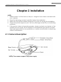
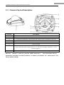
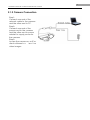
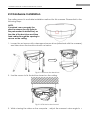
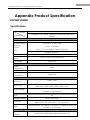
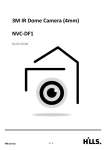
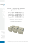
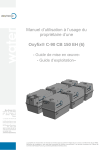
Network Mini Dome Camera Installation Manual Thank you for purch asing our product . If there are any questions, requests, please do not hesitate to contact the dealer. This man ual appl ies to the VSIP2MPVDMINI Network Camera. or This manual may contain sev eral technical incorrect places or pri nting errors, and the co ntent i s subj ect to change without noti ce. T he updates will be added to the new version of this manual. We will readily improve or update the products or pro cedures described i n the manual. 1 Installation Manual of Network Mini Dome Camera Safety Instruction These instructions are intended to ensure that the user can use the product correctly to avoid danger or property loss. The precaution measure is divided into ‘Warnings’ and ‘Cautions’: Warnings: Seri ous injury or death may be caused if any of these warnings are neglected. Cautions: Injury or equi pment damage may be caused if any of these cautions are neglected. Warnings Follow these safeguards to prevent serious injury or death. Cautions Follow these precautions to prevent potential injury or material damage. Warnings: 1. In the use of the product, you must strictly comply with the electrical safety regulations of the nation and region. 2. Source w ith DC 12V according to the IEC60950-1 standard. Please refer to technical specifications for more details. 3. Do not connect several devices to one power adapter as an adapter overload may cause ov er-heating and can be a fire hazard.If use the POE as the power supply, please make sure that the POE Switch have the sufficient power. 4. Please make sure that the plug is firmly inserted into the power socket. 5. When the product is i nstalled on a wall or ceiling, the dev ice should be fi rmly fixed. 6. If smoke, odor, or noi se r ise fr om the device, turn off the power at once and unplug the power cable, then contact the service center. 7. If the product does not work properly, please contact your dealer or the nearest service center. Never attempt to disassemble the camera yourself. (We shall not assume any responsibility for problems caused by unauthorized repair or 2 Installation Manual of Network Mini Dome Camera maintenance.) 3 Installation Manual of Network Mini Dome Camera Notice: 1. Make sure the power supply voltage is correct before using the camera. 2. Do not drop the camera or subject it to physical shock. 3. Do not touch sensor modules with fi ngers. If cleaning is necessary, u se a clean cloth with a b it of ethanol and wipe it gently. If the camera wi ll not b e used for an extended period of time, put on the lens cap to protect the sensor from dirt. 4. Do not aim the ca mera at the sun or ex tra bright places. A bloomi ng or smear may occur otherwi se (whi ch i s not a ma lfunction howev er), and affecti ng the endurance of sensor at the same time. 5. The sensor may be burned out by a lase r beam, so when any laser equipment i s being used, make sure that the surface of the sensor will not be exposed to t he laser beam. 6. Do not place the camera in extremely ho t or cold temperatures (the operati ng temperature should be between -10°C ~ 60°C, dusty or damp locations, and do not expose it to high electromagnetic radiation. 7. To avoid heat accumulation, good ventilation is required for a proper operating environment. 8. While shipping, the camera should be pa cked in its original packing, or packing of the same texture. 9. Regular part replacement: a few parts (e. g. electrolyti c capac itor) of the equipment should be replace d regularly according to the ir av erage l ife time. The av erage time v aries because of di fferences between operating environment and usage history, so regular checking is recommended for all users. Please contact with your dealer for more details. 4 Installation Manual of Network Mini Dome Camera Table of Contents Chapter 1 Introduction .....................................................................................1 1.1 Network camera Functions and Features..........................................1 1.2 Applications ............................................................................................1 Chapter 2 Installation ........................................................................................2 2.1 Camera Description ..............................................................................2 2.1.1 Camera Physical Description ......................................................3 2.1.2 Camera Connection ....................................................................4 2.2 Hardware Installation.............................................................................5 Appendix Product Specification .....................................................................8 VSIP2MPVDMINI.............................................................................................8 Specification.........................................................................................8 Dimensions ............................................................................................9 1 Installation Manual of Network Mini Dome Camera Chapter 1 Introduction Network camera i s a ki nd of embedde d d igital sur veillance product that combines the features of both trad itional analog camera an d network DVS (D igital Video Server). Due to the embedded Linux operation system and the latest Davinc i hardware platform of TI, th e system op erates wi th high scheduling effic iency. Furthermore, the fi rmware is burned i n the flash, whi ch makes the product small, reliable and highly stable. 1.1 Network camera Functions and Features Functions: Network Functi on: Support the T CP/IP pr otocols (DDNS, PPPoE, FT P, SMT P, NTP , HTTPS, SIP addible) and IE browsing. Heartbeat Function: The server can acquire real time operating performance of the network camera through the heartbeat function. Alarm Function: Supports Motion Detection. User Management: Support multilevel right management. The administrator can create up to 15 separate user s with d ifferent right lev els, which highly improves the system security. Compression Functions: Support 1 channel v ideo si gnal an d standard H. 264 v ideo encodi ng compression, whi ch supports both v ariable bi t r ate and var iable fr ame rate; besides, you can self-define both the video quality and its compressed bit rate. Remote Control: The product offers a 10M/100M self-adaptive Ethernet interface. Support various protocols. Set the parameters, browse real time videos or check the camera performance through software or IE, and store the compressed bit rate through network. Support remote upgrades and maintenance. 1.2 Applications This camera is ideal for remote control network applications. E.g.: 1. Network surveillance for supermarkets and factories. 2. Remote surveillance for homes and offices. 3. Indoor monitoring scenes, such as hotel, corridor, stairway. 2 Installation Manual of Network Mini Dome Camera Chapter 2 Installation NOTE: 1. Please check i f all the items on the pa ckage li st hav e bee n i ncluded wi th your camera. 2. Read the following contents carefully before the installation. 3. Make sure that all the related equipment is power-off during the installation. 4. Check the power supply to prev ent an y dama ge cause d by m ismatching problems. 5. If the product does not operate properly , please contact your dealer or the nearest ser vice center. Nev er attempt to d isassemble the camera yourself. Users are responsi ble for any problem ca used by mod ification or repai ring without authorization. 2.1 Camera Description NOTE:The camera supports PoE power supply. 3 Installation Manual of Network Mini Dome Camera 2.1.1 Camera Physical Description Serial NO. Description 1 Back box 2 Lens 3 P: Power LED indicator, which turns red when power is applied to the unit. 4 Bottom board 5 Bottom board set screw hole 6 Lens set screw 7 S & L: Network status LED indicator. When the network is connected, the “S” LED turns orange, while the “L” LED flickers in green. 8 RESET: Reset all paramaters to factory default settings. NOTE: When the camera is power up, press the “RESET” button for a bout 10 seconds, then all parameters, including user name, password, IP address, port number, etc., will be reset to the factory default settings. 4 Installation Manual of Network Mini Dome Camera 2.1.2 Camera Connection Step1: Connect one end of the network cable to the camera and the other end to PC. Step2: Connect one end of the power cord to the camera and the other end to power sokcket to supply power for the camera. Step3: Access the camera ov er IE or client software to v iew l ive video images. 5 Installation Manual of Network Mini Dome Camera 2.2 Hardware Installation The ceiling mount is a suitable installation method for this camera. Please stick to the following steps: NOTE: If required, user can apply the pliers to remove the clip (refer to the part marked in dotted line) on the side of the back box and then feed cables through the opening to secure on the ceiling. 1. Loosen the set screws with a hexagonal screw driver (attached with the camera), and take down the back box shown as below: Fig. 2.2.1 Remove the back box 2. Use the screws to fix the bottom board on the ceiling. Fig. 2.2.2 Fix the bottom board 3. While v iewing the video on the computer , adj ust the camera’s view angle fo r 6 Installation Manual of Network Mini Dome Camera your need. Loosen the lens set screws Adjust horizontally and vertically the camera’s pan and tilt for your need NOTE: As the lens of camera has already been factory adjusted to the best imaging effect, thus it only needs to adjust the pan and tilt view angle. If the image is not clear without the back box, please don’t worry, the back box will affect the imaging effect, so when you test the imaging effect of lens, the back box must be installed to the camera. 4. Tighten the set screws, and install the back box. Tighten the lens set screws 7 Installation Manual of Network Mini Dome Camera Fig.2.2.3 Install the back box Fig.2.2.4 Done 8 Installation Manual of Network Mini Dome Camera Appendix Product Specification 96,3039'0,1, Specification Model Parameter 2 Megapixel 1/3” CMOS Vandal-Proof Network Mini Dome Camera Camera Image Sensor 1/3” CMOS Min. Illumination Electronic Shutter 0.5Lux @(F1.2, AGC ON) 1/25s ~1/100,000s 4mm, F1.2 Fixed Iris(2.8, 6, 8mm optional) Lens Angle of view: 90° Lens Mount M12 Adjustment Range Pan±15°, Tilt0 ~90°, Rotation±15° Day / Night Electronic Compression Standard Video Compression Bit rate Audio Compression H.264 32 Kbps~16Mbps OggVorbis Image Max. Image Resolution 1600 x 1200 Frame Rate 50HZ:12.5fps (1600 x 1200), 25fps (1280 x 720) 60HZ:15fps (1600 x 1200), 30fps (1280 x 720) Image Settings Saturation,Brightness,Contrast,Tue adjustable through client software or web browser Function e-PTZ Intelligent Alarm Protocols Basic Yes Motion Detection TCP/IP,HTTP,DHCP,DNS,DDNS,RTP/RTCP,PPPoE,FTP,SMTP,NTP (SNMP,HTTPS, SIP, SRTP, 802.1x, IPV6 optional ) Initial Set button, Anti-flicker, Dual Stream, Heartbeat, Password Protection, Watermark Interface Communication Interface 1 RJ45 10M / 100M Self-adaptive Ethernet port 9 Installation Manual of Network Mini Dome Camera General Operating Condition -10°C~60°C(14°F~140°F), Humidity 90% or less(non-condensing) Power Supply DC12V±10% / PoE Power Consumption 3W MAX Impact Protection Weather Proof Dimensions(mm) Weight Dimensions IEC60068-2-75Eh,50J;EN50102, IK10 IP66 100×97.5×46.5(3.94”X3.84”X1.83”) 250g(0.55lbs)