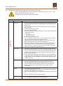
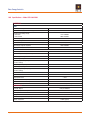
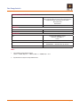
1
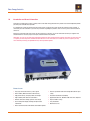
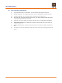
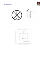
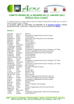
Orion
HIGH EFFICIENCY GRID FEED INVERTER
Models: SPG-360-2K0-1
O P E R AT I O N & I N S TA L L AT I O N M A N U A L
Serial No:
Model No:
S O L A R E N E R G Y A U S T R A L I A P t y L t d ACN 081 639 938
SYDNEY 4 BEAUMONT RD MT KURING-GAI NSW 2080 TEL (02) 9457 2277 TOLL FREE 1800 779 668 FAX (02) 9457 2255
Email [email protected] Web www.solaraustralia.com.au
Solar Energy Australia
TABLE OF CONTENTS
1.0Introduction and General Information3
2.0
Solar Energy Australia Warranty Terms and Conditions4
3.0
Important Safety Information
4.0
Product Overview
7
4.1
Product Description
7
4.2
Front Panel Display and Connections7
5
5.0Installation
9
5.1
Important Information9
5.2
Unpacking the Inverter9
5.3
Mounting the Inverter9
5.3.1 Selecting the Mounting Location9
5.3.2 Mountintg the Inverter to the Wall10
5.4
Electrical Installation
12
5.4.1 Connecting to the AC Mains Grid12
5.4.1.1 Compatibility Checks12
5.4.1.2 Connection to the Switchboard13
5.4.1.3 Connecting the AC Output Cable13
5.4.2 Connecting to the PV Array (DC)14
5.4.2.1 PV Array Design Requirements15
5.4.2.2 Connecting the PV Array Cables to the Inverter17
5.4.2.3 Earthing of PV Array Frames18
5.4.3 Installing Communications Interfaces18
5.5
5.6
5.7
Commissioning the PV Generating System18
Shutting Down the PV Generating System20
Replacement of Inverter20
6.0
Operating the Orion
21
6.1
Operating Modes
21
6.2
Using the LCD Display24
6.2.1 Adjusting the LCD Contrast25
6.2.2 Locking the LCD25
6.2.3 LCD Backlight26
6.2.4 LCD Accurancy26
6.3
6.4
Maximum Power Point Tracking (MPPT)26
LED/LCD Display Messages26
7.0
Communications Options
29
7.1
RS232 Interface
29
7.2
RS485 Interface (Optional)29
8.0
Maintenance and Repair
30
8.1
Visual Inspection
30
8.2
Annual Inspection and Cleaning30
9.0
Troubleshooting Guide
31
9.1
User Diagnostics
31
9.2
Fault Messages and Diagnostic Procedures for use by Solar Installers only31
10.0 Specifications - Model SPG-360-2K0-134
Page 2
Doc No SPG-1602C Rev 7/12/2011 Orion Manual
Solar Energy Australia
1.0
Introduction and General Information
Thank you for choosing to purchase a quality inverter from Solar Energy Australia. This product has been developed to provide
you with years of trouble free operation.
It is important to us that you get the best out of your inverter, so please take a few minutes to read this manual carefully; it
could save you from frustration. If you have any comments regarding our products and / or service, please do not hesitate to
contact us.
Keep these instructions with your inverter for quick reference at all times. In case of malfunction contact your supplier who
should initiate the necessary steps for analysis and elimination of the problem
Remember: As soon as your Solar Energy Australia product has been installed please complete and return your warranty card
or register your warranty online at www.solaraustralia.com.au. This will enable us to handle any service enquiries you may
have efficiently, and keep you updated with any relevant product updates.
Features Include:
• Very high conversion efficiency >94% typical
• Built in MPPT (Maximum Power Point Tracker)
• High power density, compact profile, low weight
• High reliability with dual micro controllers
• Natural convection cooling, quiet fan-less design
• User friendly LCD display showing complete status
information
• RS232 communications with RS485 and network options
Doc No SPG-1602C Rev 7/12/2011 Orion Manual
• Solar array isolation and earth leakage detection for your
safety
• Australian Certificate of Suitability
• Approved to AS 4777, AS/NZS 3100 and C Tick compliant
• Stylish, modern casing
• Easy installation
• Maintenance free
Page 3
Solar Energy Australia
2.0
Solar Energy Australia Warranty Terms and Conditions
IMPORTANT: YOU MUST REGISTER YOUR WARRANTY
Your warranty can be registered by either completing and returning your warranty card or online at www.solaraustralia.com.au.
It is extremely important that all installation instructions contained within this manual are strictly adhered to. Failure to do so will
void your warranty.
If this unit is installed within 1km of the coast steps should be taken to prevent salt water or spray entering the unit. Any
corrosion related problems are not covered under the terms of this warranty. A fully marine version of this unit is not available.
Solar Energy Australia warrants this inverter against defects in material or workmanship, for a period of five (5) years from
the date of purchase, when in normal use and service. The warranty period will provide a total of five (5) years if a completed
warranty card is received within 60 days of purchase. No warranty will be provided on units, which have not been paid for in full.
Some models may have the option of purchasing an extended warranty period; see elsewhere in this manual for details. This
manufacturer’s warranty is in addition to your consumer rights under local trade practices act.
This warranty does not extend to products which have been opened, altered or repaired by persons other than those authorized
by Solar Energy Australia or to products which become defective due to acts of God, fire, sabotage, vandalism, contaminated
fluids, negligence or failure to operate, house and maintain the product in accordance with instructions provided in this manual.
This warranty does not cover repairs made necessary due to the product coming in contact with dirt, abrasives, moisture,
erosion, corrosion, varnish or other similar, or failure due to poor quality of other system components.
Solar Energy Australia will repair or replace the defective product in accordance with its best judgment. For service under
warranty, the buyer must contact Solar Energy Australia to obtain a “Return Materials Advice” (RMA) document and shipping
instructions before returning the unit. Products returned without prior authorization may be delayed. The buyer will pay all
charges incurred in returning the product to the factory, including any charges incurred for the removal or reinstallation of the
inverter and / or its system components. Solar Energy Australia will pay return freight charges, if the product is found to be
defective, within the terms of this warranty. Repair or replacement of any unit does not extend the original warranty terms in any
way.
Solar Energy Australia reserves the right, with some models, to supply an accredited installer with replacement parts (Aust.
only). This may allow the unit to become operable much quicker. This choice is at Solar Energy Australia’s discretion. Solar
Energy Australia will in no way be held responsible for any losses incurred due to the malfunctioning or failure of a product.
Suitably qualified personnel MUST carry out wiring. Failure to do so cannot justify a warranty claim.
Except for the foregoing expressed warranty, Solar Energy Australia makes no other warranty, expressed or implied, including
but not limited to, the warranty of merchantability or fitness for a particular purpose.
If you have any questions about this warranty please do not hesitate to contact us.
NOTE: Packing for service and transportation - we recommend you keep the original packing in which your Orion was supplied.
This is the best way to protect your unit should shipping be required.
Solar Energy Australia cannot be held responsible for units damaged in transit.
Page 4
Doc No SPG-1602C Rev 7/12/2011 Orion Manual
Solar Energy Australia
3.0 Important Safety Information
Before commencing installation please read carefully and follow the recommended guidelines below for trouble-free operation.
DO NOT remove the cover. This inverter contains no user serviceable parts. Removal of the cover will
invalidate the warranty and may result in injury. Energy stored in this equipment’s internal DC link capacitors
presents a risk of electric shock if the cover is removed. The inverter must be returned to SEA for servicing.
Grid feeding inverters convert the DC current derived from solar arrays into AC current that is fed into the LV
(low voltage) electricity distribution grid.
DO NOT connect a wind generator, turbine or battery bank to the input of this inverter, severe damage will result. Only PV panels
may supply the unit.
DO NOT connect the output of this inverter to a standalone inverter or generator. This inverter may only be connected to the LV
electricity grid.
IMPORTANT: Isolate this inverter from both the PV array and mains grid BEFORE commencing any installation or service work.
DO NOT disconnect the inverter’s PV input connectors under load. De-energize the system by turning off the solar supply
main switch, AC isolation device (if present), and PV array DC isolator(s) before disconnecting the PV input
connectors.
All system wiring including the PV array and associated wiring must be installed by a licensed electrician and
accredited solar installer.
The entire generating system MUST be designed and installed in accordance with AS/NZS3000, AS4777, AS/NZS5033 and any
requirements of the local electricity utility. Particular attention must be paid to the design of and selection of components for the
following:
•
•
•
•
•
PV and mains disconnection devices
PV and mains fault current protection
PV cable selection, current rating and insulation
PV system and equipment earthing including earthing of PV array frames
PV module equipment class and required approvals.
Protection from lightning should be provided per AS/NZS1768.
This inverter is a non-isolated (transformerless) grid-feeding inverter. LV mains voltage will be present between the PV array and
earth when the inverter is operating. This inverter is classified as a “non-isolated PCU” per AS/NZS5033.
The PV array framework must be bonded to protective earth with an earthing conductor sized according to AS/NZS3000.
When connecting and disconnecting the PV array to this inverter, protective earth must remain connected to the inverter. The plug
making the AC mains grid connection to the Orion must be connected first and disconnected last. The connector provided is a
permanently latching type requiring the use of tools for removal to avoid inadvertent disconnection.
This inverter has an integral GFCI (ground fault current interrupter) which detects residual current in the system ground. This
circuit disconnects the inverter from the grid if this current is greater than 30mA. This circuit provides protection from a ground
fault in the PV array or accidental contact with the PV array circuitry.
Generally, this inverter is not suitable for use with thin film PV panels. Check with your panel manufacturer that the PV panels can
be used with a non-isolated (transformerless) grid feeding inverter.
Do not install this inverter near flammable items. Keep explosive vapours away from the inverter.
This inverter is not designed for outdoor use. Protect the unit against rain, splashing water and salt spray. Install it in a dry, saltfree location with adequate ventilation and maximum humidity of 95% non-condensing. Do not expose the unit to direct sunlight
and ensure that the ambient temperature is less than 55°C, preferably less than 40°C. Allow a minimum of 200mm for ventilation
on all sides of the unit. Keep the black heatsink fins free of dust and obstructions to airflow. Inadequate air circulation can lead to
overheating and overload.
Doc No SPG-1602C Rev 7/12/2011 Orion Manual
Page 5
Solar Energy Australia
Hot Surfaces
Although this unit is designed to meet all safety requirements some parts and surfaces will become hot
during operation. To reduce the risks of injury, do not touch the black finned heat sink at the rear of the unit
or nearby surfaces whilst the Orion is operating.
Page 6
Doc No SPG-1602C Rev 7/12/2011 Orion Manual
Solar Energy Australia
4.0 Product Overview
4.1
Product Description
The SPG-360-2K0-1 Orion is a highly efficient true sine wave, DC/AC inverter designed for solar grid-feeding applications.
The unit operates from a photovoltaic (PV) solar array DC power source and generates a 240Vac, 50Hz current output
for direct connection to the LV (low voltage) power grid. The unit operates with an input voltage between 125VDC and
400VDC. The absolute maximum non-operating input voltage is 500VDC. The Orion employs an MPP (maximum power
point) tracker for efficient operation with PV power systems. It provides a maximum continuous output power of 2000W to
the AC grid with a short duration rating of 2200W. The inverter automatically limits output power.
The SPG-360-2K0-1 Orion is protected to IP43 and is designed for indoor use only. It employs natural convection cooling
with no cooling fans, resulting in high reliability and quiet operation.
Operating status and alarms are provided by a 16 character LCD display on the front panel with an intuitive Englishlanguage menu system.
The Orion is provided with a standard RS232 socket for connection to a PC for data acquisition. There are optional
components for communications and logging via RS 485.
The Orion is compliant with: AS 4777:2005 “Grid Connection of Energy Systems Via Inverters”, and AS/NZS 3100: 2009
“Approval and test specification – General requirements for electrical equipment”.
Doc No SPG-1602C Rev 7/12/2011 Orion Manual
Page 7
Solar Energy Australia
4.2
Front Panel Display and Connections
(1)
Display Information Switch / Function Button. Press this button to scroll through the LCD menu.
(2)
Operation LED (Green): This LED lights whenever the inverter is supplying power to the AC mains grid.
(3)
Fault Status LED (Red): This LED turns on if there is a system fault or an inverter fault.
(4)
Solar Panel Input: DC input for connection to the PV array. Refer to the installation section of this manual
for PV array design and connection information.
(5)
RS232 Port: This interface allows direct communication with a PC via a standard RS232 DB9 COM port.
(6)
Optional Communications Port: An optional port to extend the communication interface; for example by
installing an RS485 card.
(7)
AC Output Utility Connection: Three pole latching connector for connection to the 240Vac, 50Hz AC mains
grid.
(8)
LCD Display: A 16 character alphanumeric display which shows inverter status, operating parameters and
alarms.
Page 8
Doc No SPG-1602C Rev 7/12/2011 Orion Manual
Solar Energy Australia
5.0Installation
5.1
Important Information
ALL WORKS MUST BE CARRIED OUT BY A LICENSED ELECTRICIAN AND AN ACCREDITED SOLAR INSTALLER.
The entire generating system MUST be designed and installed in accordance with AS/NZS3000, AS4777 and AS/NZS5033
and any requirements of the local electricity utility.
Note: This unit is classified as a “non-isolated PCU” as per AS/NZS5033.
5.2 Unpacking the Inverter
Carefully remove the unit from its packaging and inspect for external damage before installation. Please contact your
supplier if the unit is damaged.
Check that the package contains the following:
•
•
•
•
•
•
•
•
•
1 x SPG-360-2K0-1 inverter
1 x 4mm2 PV input cable with male cable coupler installed.
1 x 4mm2 PV input cable with female cable coupler installed.
Operation and installation manual.
Inverter mounting bracket.
4 x mounting screws and 4 x snap bushings.
2 x safety locking screws.
1 x AC output connector.
SEA warranty card
5.3 Mounting the Inverter
5.3.1
Selecting the Mounting Location
To obtain the best results from your inverter, please consider the following before installing the device:
• DO NOT expose the inverter to direct sunlight. Direct sunlight increases the internal temperature of the
inverter which reduces its conversion efficiency.
• Choose a dry location which is out of direct sunlight, free of salt or moisture-laden air, free of dust and not
accessible to rodents.
• Provide adequate cooling space around the inverter.
• Ensure that the ambient temperature remains within the specified range -20°C to +55°C under all conditions.
Although the inverter can operate at up to 55°C, continuous operation at high temperature will shorten
its lifespan. For optimal operation, it is recommended that the inverter be installed where the ambient
temperature during full power operation is between 0°C and 40°C.
• Do not install the inverter in a cupboard or small enclosure as this will increase its operating temperature,
lower its reliability, and reduce its output power.
• The inverter should not be installed in areas exposed to high humidity and condensation. Humidity should be
in the range 0 to 95% non-condensing.
• Do not install the inverter near flammable items. Keep explosive vapours away from the inverter.
• The inverter is heavy (11.3kg). Select a wall or solid vertical surface which is strong enough to support this
weight.
• The inverter must be mounted vertically. Ensure that the inverter does not tilt forward. Do not mount the
inverter horizontally. Do not place any items on the top of the inverter as this will block the cooling airflow.
Doc No SPG-1602C Rev 7/12/2011 Orion Manual
Page 9
Solar Energy Australia
5.3.2
Mounting the Inverter to the Wall
1. Locate the inverter so that there is at least 20cm of cooling space at the top and bottom and ideally also on the
sides to allow access to the safety screws.
Page 10
Doc No SPG-1602C Rev 7/12/2011 Orion Manual
Solar Energy Australia
2. Using the mounting bracket as a template, drill four holes and drive the four snap bushings into the holes. Insert
the mounting screws and tighten the mounting bracket to the wall. Do not over-tighten the screws as the bracket
may distort unless the wall is perfectly flat.
3. Mount the inverter on to the bracket as shown below
4. Install the two safety locking screws into the threaded holes in the sides of the inverter
IMPORTANT: After hanging the unit, make sure that the safety locking screws are fitted properly and that the inverter
cannot be lifted from the mounting bracket
Doc No SPG-1602C Rev 7/12/2011 Orion Manual
Page 11
Solar Energy Australia
5.4
Electrical Installation
WARNING: When connecting and disconnecting the PV array to/from this inverter, protective earth must remain connected. The AC mains grid must be connected first and disconnected last.
5.4.1
Connecting to the AC Mains Grid
5.4.1.1
Compatibility Checks
Before connecting the inverter to the AC grid, please check the following:
• Confirm that the AC grid voltage is within the range 206-264Vac. These are the under- and over-voltage
protection limits beyond which the inverter will not generate any power.
• Confirm that the AC frequency is within the range 49.25-50.75Hz. These are the under- and over-frequency
limits beyond which the inverter will not generate any power.
• If the local utility requires different grid under- and over-voltage or under- and over-frequency limits, these
parameters can be changed. Please contact your supplier.
Page 12
Doc No SPG-1602C Rev 7/12/2011 Orion Manual
Solar Energy Australia
5.4.1.2
Connection to the Switchboard
Connections to the main switchboard or a distribution board must comply with the appropriate requirements of AS/
NZS3000 and AS4777.1. Many configurations are acceptable. The following diagram is an example of a typical
configuration with a connection to the main switchboard.
In all installations, the following items must be provided.
• Solar supply main switch and overcurrent protection. This is located in the main switchboard or distribution
board to which the inverter is to be connected. This part typically consists of a single pole lockable 16A circuit
breaker.
• AC Isolation device. If the inverter is located more than 3 meters away from the main switchboard or
distribution board to which it is connected, or if the inverter is not in clear view of this board, an AC isolation
device must be provided adjacent to the inverter. This device must be rated to interrupt the maximum AC
output current from the inverter (10.5A).
5.4.1.3
Connecting the AC Output Cable
WARNING: Ensure that the solar supply main switch, AC isolation device (if present) and PV Array DC isolator
are turned off and locked before starting any wiring.
Doc No SPG-1602C Rev 7/12/2011 Orion Manual
Page 13
Solar Energy Australia
The AC connection to the Orion is made via a Weiland Electric RST 20i3 latching connector (p/n 96.031.4153.1)
supplied with the unit. SEA recommend using a minimum 1.5mm2 3 core cable.
N
Plug
Shroud
A
E
Gland
Completed Assembly
Fit the shroud and cable gland over the cable. Strip the cable. Wire the plug as follows:
Active = A=Brown,
Neutral=N=Blue,
Earth=E=Yellow/Green
Securely tighten the clamping screws. Clip the shroud to the plug and tighten the cable gland securely.
Plug the AC output connector into the unit and ensure that it latches positively. If it is desired to remove the
connector, it can be removed by carefully depressing the grey latch tongue with a small screwdriver.
5.4.2
Connecting to the PV Array (DC)
WARNING: The SPG-360-2K0-1 Orion is a non-isolated grid-feeding inverter. LV mains voltage and DC voltages
up to 500Vdc with respect to ground will be present on the PV inputs when the unit is operating. All system wiring
including the PV array and associated wiring must be installed by a licensed electrician and accredited solar
installer.
Page 14
Doc No SPG-1602C Rev 7/12/2011 Orion Manual
Solar Energy Australia
5.4.2.1
PV Array Design Requirements
The PV array design and installation must comply with the requirements of AS/NZS5033 for connection to a nonisolated PCU.
The maximum output power versus input voltage (VPV) for the SPG-360-2K0-1 Orion is shown in the following
diagram.
Formula
Curve
For Input Vdc > 250V,
Output% = 100% (2000W)
(+10%: 2200W short duration)
For Input Vdc ≤ 250V,
Output% = 0.4 x VPV
Example:
VPV = 200Vdc
Output% = 0.4 x 200
= 80% (1600W)
To obtain full output power, approximately 20-25m2 of PV panels will be required assuming average efficiencies.
These must be configured so that the PV maximum power point voltage is in the range of 125 – 400Vdc. For full
output power, the PV input voltage must be in the recommended range of 250 – 400Vdc.
The maximum open circuit voltage of the PV array (VOC) must be less than 500Vdc under all conditions. VOC
increases at low ambient temperature. This increase must be included when designing the PV array.
The inverter efficiency increases as input voltage VPV increases. Configure the PV array so that the maximum
power point voltage is as high as possible while ensuring that the open circuit voltage at the minimum ambient
temperature is less than 500Vdc.
The SPG-360-2K0-1 is rated to a maximum input current of 10A. The inverter will actively limit the input current to
10A. This current limit reduces the available output power from the inverter with input voltages below 250Vdc as
shown in the above figure.
Doc No SPG-1602C Rev 7/12/2011 Orion Manual
Page 15
Solar Energy Australia
PV arrays with maximum power point voltages less than 250Vdc are not recommended as the low voltage reduces
the maximum available output power from the inverter and the inverter efficiency.
The maximum PV array short circuit current (ISC) must be less than 20A. This current can flow in the event of an
internal failure in the inverter.
The 10A input current limiter allows operation of the Orion with an oversized PV array which is able to supply
greater than 10A. However, if an oversized array is to be used, the maximum PV array output power must be less
than 2400W at 400Vdc.
In all installations a PV Array DC isolation device must be provided between the output of the PV array and the
input of the inverter. This isolation device must be lockable, be rated for load-breaking and it must comply with the
requirements for current breaking switching devices per AS/NZS5033. This part must break both poles of the array
simultaneously. Typically a DC-rated circuit breaker can be used as the PV Array DC isolation device. Note that DC
circuit breakers are polarity sensitive. This part must be located close to the inverter. It must not be installed in
the AC main switchboard or distribution board to which the output of the inverter is connected.
DO NOT disconnect the inverter’s PV input connectors under load. De-energize the system
by turning off the solar supply main switch, AC isolation device (if present), and PV array DC
isolator before disconnecting the PV input connectors.
The following diagram shows a typical connection between a PV array and the SPG-360-2K0-1.
Page 16
Doc No SPG-1602C Rev 7/12/2011 Orion Manual
Solar Energy Australia
5.4.2.2Connecting the PV Array Cables to the Inverter
The input terminals on the SPG-360-2K0-1 are either Multicontact MC4 series or Wieland Electric PST40i1
connectors. The SPG-360-2K0-1 is supplied with a pair of 4mm2 PV input cables terminated with the appropriate
cable couplers from the same manufacturer.
WARNING: Always use cable couplers from the same manufacturer as the input terminals on the inverter. Do not
use connectors from different manufacturers as this can cause a fire hazard. Use the input cables supplied with
the unit.
WARNING: Ensure that the solar supply main switch, AC isolation device (if present) and PV Array DC
isolator(s) are turned off and locked before connecting the PV array to the inverter. Confirm that the
AC mains connections have been completed before connecting the PV array to the inverter. Ensure
that the inverter has been connected to protective earth.
Connect the inverter PV array(s) to the inverter as follows.
1. Connect the input cable to the PV Array DC isolator. The cable with the female connector is connected to the
positive voltage. The cable with the male connector is connected to the negative voltage. Do not connect the
cables to the input of the inverter at this time.
2. With full sun on the PV array, turn on the PV Array DC isolator and measure the open circuit voltage at the input
cable connectors. Ensure that this voltage is within design limits and is less than 500Vdc. Check that the
polarity is correct. Turn off the PV Array DC isolator.
3. Short circuit the PV array positive and negative cables through a DC ammeter. With full sun on the PV array,
turn on the PV array DC isolator and measure the short circuit current. This must be less than 20A. Turn off the
PV array DC isolator.
4. Connect the PV array cables to the input of the inverter.
Doc No SPG-1602C Rev 7/12/2011 Orion Manual
Page 17
Solar Energy Australia
5.4.2.3
Earthing of PV Array Frames
The frames of all PV panels connected to the SPG-360-2K0-1 must be connected to protective earth to prevent
electric shock hazards. The earthing cables must be sized following the appropriate requirements of AS/NZS3000
and AS/NZS5033. In particular, current rating of earthing cable must follow the same rules as for the current rating
of PV array circuits defined in table 3.1 of AS/NZS5033.
Attention must be paid to the possibility of galvanic corrosion due to dissimilar metals of the array frames (typically
anodized aluminium) and the earthing cable (copper). Earthing lugs must be able to cut through the anodized
finish on the panel frames as this is an electrical insulator. Also, these cables must be configured so that on
disconnection and removal of any panel or the inverter, all other panels remain connected to protective earth.
Installing Communication Interfaces
5.4.3
The SPG-360-2K0-1 can communicate operating data and status via an RS232 interface or an optional RS485
network card. Details of these interfaces are provided in section 7.0. The interfaces must be connected with the
inverter de-energized. If possible, it is best to do this installation before commissioning the generating system.
Commissioning the PV Generating System
5.5
Commissioning the PV generating system must follow the requirements of the energy utility.
Once permission has been granted, start up the inverter as follows:
1. Confirm that all system wiring has been done correctly.
2. Check that the AC mains grid compatibility checks have been performed.
3. Check that the PV array open circuit voltage and short circuit current have been measured and that these are
within the ratings of the inverter.
4. Turn on the PV array DC isolator.
Once the input voltage is greater than approximately 100Vdc, the LCD display will show the following screens
in sequence.
VPV > 100Vdc
Page 18
Doc No SPG-1602C Rev 7/12/2011 Orion Manual
Solar Energy Australia
VPV > 150Vdc
Once the input voltage VPV goes above 150 Vdc, the red fault LED
turns on showing that no AC utility is present.
Turn on the solar supply main switch and the AC isolation device (if
present).
5.
After a few seconds, the inverter shows the following screen
momentarily. This indicates that the inverter has detected the AC
grid. The red fault LED is then turned off.
If the input voltage VPV is less than 150Vdc the inverter shows this
screen.
VPV > 150Vdc
Once the input voltage VPV goes above 150Vdc, the inverter
attempts to connect to the AC mains grid. The inverter monitors
the grid voltage and frequency for 60 seconds before it connects.
The display counts down from 60S to 00S.
Checking 00S
Doc No SPG-1602C Rev 7/12/2011 Orion Manual
Page 19
Solar Energy Australia
At 00S, the inverter clicks several times as it tests its internal
grid connect relays. Once the microcontrollers are satisfied that
all is in order, the unit closes the grid connect relays and starts to
feed power to the grid. The green power LED turns on.
Over a few minutes the output power Pac reading rises from
0.0W to the maximum power point output power.
The inverter is now “on line” and is feeding solar power to the
grid.
5.6
Shutting Down the PV Generating System
If the PV generating system has to be shut down, the shutdown procedure is the reverse of the commissioning
procedure as follows.
1. Turn off the AC isolation device (if present) and the solar supply main switch.
2. Turn off the PV array DC isolator.
Replacement of Inverter
5.7
If the inverter has to be replaced, disconnecting and removing the inverter is the reverse of this installation
procedure keeping in mind the following.
Ensure that the solar supply main switch, AC isolation device (if present) and PV Array DC isolator are
turned off and locked before disconnecting the inverter.
When disconnecting the PV array from this inverter, protective earth must remain connected. The AC
mains grid must be disconnected last.
DO NOT disconnect the inverter’s PV input connectors under load.
Page 20
Doc No SPG-1602C Rev 7/12/2011 Orion Manual
Solar Energy Australia
6.0 Operating the Orion
6.1
Operating Modes
Once it has been commissioned, the SPG-360-2K0-1 operates automatically.
The Orion has 3 modes of operation: shutdown, operating and fault modes
1.
Shutdown Mode: During periods of little or no sunlight (VPV < 70Vdc approximately), the Orion stops running. In
this mode the Orion takes no power from the grid, the front panel LCD and LEDs are turned off and the function
button is inactive. The inverter is in this state at night.
2.
Operating Mode: In this mode, the PV generating system and inverter are operating normally. Depending upon the
amount of available sunlight, the inverter may or may not be generating power into the AC mains grid. The inverter
monitors the PV array and adjusts its own operation appropriately. In this mode, there are three general sequences
of operating states which the Orion follows: normal state, initial startup sequence, and reconnect sequence.
a)
Normal State
In normal state, the inverter is connected to the AC mains
grid and is generating power into it. The inverter stays in
this state so long as there is sufficient sunlight and there
are no faults.
b)
Initial Startup Sequence: Waiting->Checking->Normal
States
In the morning, the inverter goes through a sequence of
states as it initially connects to the AC mains grid and
starts to generate power.
Waiting: As the sun rises, the input voltage VPV starts to rise
from 0V. When this voltage reaches approximately 100Vdc,
the inverter enters either the “Standby” or “Waiting” state.
The inverter checks it’s internal status and the display
shows the following screens.
Doc No SPG-1602C Rev 7/12/2011 Orion Manual
VPV >100 Vdc
VPV <100 Vdc
VPV >150 Vdc
VPV <150 Vdc
Page 21
Solar Energy Australia
VPV >150 Vdc
VPV <150 Vdc
Checking: Once the input voltage rises above 150Vdc, the
inverter attempts to connect to the AC mains grid. The
inverter monitors the AC mains grid voltage and frequency
for 60 seconds before it connects. The display counts down
from 60S to 00S.
If the input voltage drops below 150Vdc again, the inverter
returns to the “Waiting” state.
Checking 00S
Normal: At 00S, the inverter clicks several times as it tests
its internal grid connect relays. Once the microcontrollers
are satisfied that all is in order, the inverter closes the grid
connect relays and starts to feed power to the grid. The
inverter goes into “Normal” state. The green power LED
turns on.
Over a few minutes the output power Pac reading rises from
0.0W to the maximum power point output power.
If there is sufficient sunlight, the inverter stays in the
“Normal” state generating power into the AC mains grid.
Reconnect Sequence: Normal->Vpv Low->Standby>Waiting->Reconnect->Normal States
c)
If there is insufficient sunlight to continue generating power,
the inverter goes through the reconnect sequence as follows.
Normal: The inverter is initially in the normal state
generating power into the AC mains grid.
VPV Low/Standby/Waiting: There is insufficient sunlight to
continue generating power and the input voltage decreases
below 100Vdc. The inverter detects low input voltage and
disconnects from the AC mains grid and stops generating
power. The inverter displays “VPV Low” momentarily before
entering the “Standby” or “Waiting” states.
VPV >100 Vdc
Page 22
VPV <100 Vdc
Doc No SPG-1602C Rev 7/12/2011 Orion Manual
Solar Energy Australia
Reconnect: Once the input voltage rises above
150Vdc, the inverter attempts to reconnect to the grid.
The inverter monitors the AC mains grid voltage and
frequency for 60 seconds before it connects to the
grid. The display counts down from 60S to 00S.
If the input voltage drops below 150Vdc again, the
inverter returns to the “Waiting” state
VPV >100 Vdc
VPV <100 Vdc
VPV >150 Vdc
VPV <150 Vdc
Reconnect 00S
Normal: At 00S, the inverter connects to the grid and
starts to feed power into it. The inverter goes into
the “Normal” state. The green power LED turns on.
Over a few minutes the output power Pac reading rises
from 0.0W to the maximum power point output power.
If there is sufficient sunlight, the inverter stays in the “Normal” state generating power into the AC mains grid. If
there is insufficient sunlight (VPV < 100Vdc) , the inverter goes through this reconnection cycle repeatedly until
there is sufficient sunlight to generate power.
VPV < 100 Vdc
Note: In continuing conditions of poor sunlight, the Orion will attempt to minimize the number of reconnection
cycles by increasing the starting value of the reconnect counter from 60 seconds up to a maximum of 999
seconds. This behaviour is normal and does not indicate a fault. When sufficient sunlight becomes available, the
Orion will reconnect and stay in the “Normal” state.
3.
Fault Mode: The SPG-360-2K0-1’s two intelligent microcontrollers continually monitor the PV generating system
status. If the Orion finds any abnormal conditions, such as AC grid anomalies, it displays a message on the LCD
display, turns on the red fault LED, disconnects from the grid and stops generating power. It remains in this
mode until the cause of the fault is corrected. Descriptions of the various fault conditions detected by the
SPG-360-2K0-1 are provided in section 6.4 “LED/LCD Display Messages”.
Doc No SPG-1602C Rev 7/12/2011 Orion Manual
Page 23
Solar Energy Australia
6.2
Page 24
Using the LCD Display
The function button is used to cycle through various system parameters. These parameters can be viewed with
the inverter in any operating or fault state. This is a circular menu as shown below. If the function button is not
pressed, the menu reverts to the operating or fault state display after a few seconds.
Doc No SPG-1602C Rev 7/12/2011 Orion Manual
Solar Energy Australia
6.2.1
6.2.2
Adjusting the LCD Contrast
If the LCD is hard to read, as it may be in elevated temperatures, adjust the contrast as follows.
Locking the LCD Display
Sometimes you may wish for the LCD display to show a particular parameter indefinitely rather than reverting to
the operating or fault state display after a few seconds. The display can be locked as follows.
Doc No SPG-1602C Rev 7/12/2011 Orion Manual
Page 25
Solar Energy Australia
6.2.3
LCD Backlight
The LCD backlight turns on whenever the function key is pressed. After 30 seconds of inactivity, the backlight
switches off.
LCD Accuracy
6.2.4
The readings on the LCD are just for reference. They should not be used for metering purposes. Typically the
readings during normal operation are accurate to ±2% but accuracy can change by as much as ±5% over various
modes of operation.
Maximum Power Point Tracking (MPPT)
6.3
The SPG-360-2K0-1 tracks the maximum power for its PV input. When the output power on the LCD display is
stable, the inverter is operating at the maximum power point and is generating the maximum power available from
the PV array. When the power reading fluctuates, the inverter is tracking changes in power from the PV array due
to varying levels of sunlight.
LED/LCD Display Messages
6.4
The following table lists operating conditions / status of the SPG-360-2K0-1 and the corresponding LCD messages
and LED indications. The following colour code is used to show the LED status.
Power on LED (green) on, fault LED (red) off ••
Power on LED (green) off, fault LED (red) on ••
Both LEDs off ••
LEDS AND OPERATING
CONDITIONS
MESSAGE
DESCRIPTION
Normal Operation
• •
Power off
No display
PV inverter is shutdown VPV ≤ 70Vdc
• •
Standby
Standby
70Vdc < input voltage VPV ≤100Vdc
• •
Initialization and
waiting
Waiting
Input voltage VPV is in the range 100-150Vdc. The inverter
is waiting for the input voltage to rise above 150Vdc before
attempting to connect to the AC mains grid.
• •
Checking grid.
xxS shows
countdown to
connection.
Checking
xxS
• •
Feeding grid,
MPPT
Normal
• •
Waiting for
reconnection
to the grid.
Checking grid.
xxS shows
countdown to
connection
Reconnect
xxS
• •
Low input Voltage
Input voltage VPV >150V. The inverter is checking the grid voltage
and frequency for 60 seconds before connecting to the grid for the
first time. Once the inverter has been connected to the grid on a
particular day, Reconnect xxS is shown rather than this screen.
Inverter is feeding solar power to the AC mains grid.
The inverter was disconnected from the grid and is now
attempting to reconnect. The inverter is checking the grid voltage
and frequency for 60 seconds before connecting. In low light
conditions such as sunrise, this checking time can increase
automatically to as much as 999 seconds if there have been
several failed attempts to reconnect.
VPV Low
The inverter was previously connected to the grid and was
supplying power, but the input voltage VPV has dropped to
less than 100 Vdc due to insufficient sunlight. The inverter has
disconnected from the grid.
Pac=
XXXX.XW
Output power to the AC mains grid in Watts.
Parameter Monitoring
• •
Page 26
Instantaneous
output power
Doc No SPG-1602C Rev 7/12/2011 Orion Manual
Solar Energy Australia
LEDS AND OPERATING
CONDITIONS
MESSAGE
DESCRIPTION
• • Total Energy
Energy=xxxxxxkWh
• • Grid voltage
Vac= xxx.xV
AC mains grid voltage in Vrms.
Frequency=xx.xHz
AC mains grid frequency in Hz.
• • Grid frequency
• • Grid feeding current
Iac=xx.xA
• • PV array voltage(s)
Vdc=xxx.xV
• • Daily Energy
Etoday=xxx.xkWh
Total energy which has been fed to the grid in kWh since the inverter was
installed.
Output current to the AC mains grid in Arms.
Input voltage from PV array in Vdc.
Energy which has been fed to the grid today in kWh.
System Faults
• • Isolation failure
Isolation fault
There is an electrical fault between the PV panels or wiring and protective
earth, or the input surge suppression circuitry on the SPG-360-2K0-1 has
been damaged due to a lightning surge. This alarm will be displayed on initial
application of PV power. The inverter will not attempt to connect to the AC
mains grid until this fault is rectified.
• • GFCI active
Ground I Fault
There has been excessive leakage current from the PV array to the earth while
the inverter was generating power. The inverter has disconnected from the
grid due to this fault.
• • Grid failure
Grid Fault
The AC mains grid voltage or frequency is outside of limits (default 206V/264V,
49.25Hz/50.75Hz). The inverter has disconnected from the grid.
• • No utility
No utility
The AC mains grid is not available. There has been a mains power failure or
the AC mains grid has been turned off.
• • Input voltage too high
PV over voltage
The input voltage VPV is greater than 500V on one of the inputs.
Consistent fault
The readings of the two internal microprocessors do not agree.
Inverter Faults
• • Consistent failure
• • Temperature too high
Over temperature
Internal temperature is excessive.
• • Output relay failure
Relay failure
One of the grid connection relays is faulty.
• • Output DC injection
too high.
DC INJ High
The inverter is generating excessive DC current on the AC mains grid.
• • EEPROM problem
EEPROM Failure
The EEPROM memory inside the inverter has a data access problem
• • Communication
failure between
microprocessors
SCI Failure
• • DC bus voltage too
high
High DC Bus
Doc No SPG-1602C Rev 7/12/2011 Orion Manual
The communications between the two microprocessors has failed.
The internal DC bus voltage is higher than expected.
Page 27
Solar Energy Australia
LEDS AND OPERATING
CONDITIONS
• • DC bus voltage too
low
MESSAGE
Low DC Bus
• • 2.5V reference
voltage problem
Ref 2.5V Fault
• • Output DC sensor
problem
DC Sensor Fault
• • GFCI detection
problem
GFCI Failure
The internal DC bus voltage is lower than expected.
The internal 2.5V reference is faulty.
The DC current sensor on the output is giving an abnormal reading.
The internal ground fault current interrupter (GFCI) circuit is giving an abnormal
reading.
Inverter Information
• • Model display
SPG-360-2K0
• • LCD contrast
Contrast
• • LCD contrast setting
Set Contrast
• • LCD display lock
Lock
• • Firmware version
Ver xx.xx
• • Setting Language
Set Language
Page 28
Inverter model: SPG-360-2K0-1
The top menu of LCD contrast setting.
Set the display contrast.
The display will be held at the present screen.
F/W version information.
Set up the display language
Doc No SPG-1602C Rev 7/12/2011 Orion Manual
Solar Energy Australia
7.0 Communications Options
The Orion supports powerful communications and monitoring options. An RS232 interface is fitted as standard The unit also
supports an RS485 interface which is available at extra cost from your supplier.
The SPG-360-2K0-1 does not have an internal datalogger.
Monitoring and logging of one or more inverters can be done on a Windows PC using the “Procontrol” software package which is
available from your supplier. Using this package you can monitor one inverter via the RS232 interface or multiple inverters via the
optional RS485 interface.
SEA also has available dataloggers for monitoring and logging up to 20 inverters via the RS485 interface. Contact your supplier
for details.
WARNING: Before connecting the RS232 interface or installing and connecting the RS485 interface card, ensure that the inverter
and the PC or datalogger are both turned off. To shut down the inverter and restart it after connecting these interfaces, follow the
procedures in sections 5.6 and 5.5 respectively.
7.1 RS232 Interface
A standard 9 pin female D type connector (DB9) is provided for RS232 connection to a Windows PC. This interface is
configured as Data Circuit Terminating Equipment DCE with no flow control. It is suitable for direct connection with a PC
RS232 COM port without a null modem. The RS232 interface works over distances up to 50 metres. Pin assignments on
the DB9 connector are as follows.
Pin No.
Signal Assignment
1
NC
2
Tx Data
3
Rx Data
4
NC
5
Common
6
NC
7
NC
8
NC
9
NC
NC = No Connection
The RS232 interface is located in the centre of the unit between the PV input and the AC output connectors. To connect
to this interface, remove the two screws and hinge down the small cover. Use a straight through DB9 male to DB9 female
serial data cable to connect this interface to a COM port on your PC. Secure each connector using the jack screws on the
cable.
The COM port settings should be as follows:
• Baud rate:9600 Bits per second
• Data bits: 8
•Parity: None
• Stop bits: 1
• Flow control: None
7.2 RS485 Interface (Optional)
An optional RS485 interface card is available from your supplier. This card supports a 4 wire RS485 network allowing
multiple inverters to be connected to a PC or a datalogger over distances up to 1.2km. This card is installed in the
communications slot below the AC output connector.
To install this card, remove and keep the four screws outside of the communications card slot. Remove and keep the
two screws on the communications card slot. Configure the DIP switches on the card, feed the RS485 network cable(s)
through the gland on the cover supplied with the card and terminate these cable(s) to the card as described in its
installation instructions. Plug the card into this slot and reinstall the two screws to retain the card. Fasten the cover to the
inverter using the four screws.
Doc No SPG-1602C Rev 7/12/2011 Orion Manual
Page 29
Solar Energy Australia
8.0 Maintenance and Repair
Although the SPG-360-2K0-1 requires minimal maintenance, for continued optimal performance, the following inspections and
maintenance are recommended.
8.1
Visual Inspection
On a regular basis, check the following:
• Check that the heatsink at the rear of the inverter is free from obstructions to airflow.
• Check the inverter for any fault indications.
• Check the inverter and cabling for any sign of damage.
If any faults are displayed on the inverter, consult the Troubleshooting Guide in section 9.0 before contacting your supplier
or returning the unit for service.
In the event of an internal malfunction, the inverter must be returned to SEA for repair. The SPG-360-2K0-1 contains no
user serviceable parts.
Note: Removal of the cover will invalidate the warranty.
8.2
Annual Inspection and Cleaning
SEA recommends that a qualified solar installer inspects and cleans the inverter and PV generating system at least every
12 months. The following tasks should be performed:
• Check that the heatsink at the rear of the inverter is free from obstructions to airflow. Remove any debris or dust from
the heatsink.
• Inspect all system cabling for damage and repair if necessary.
• Confirm that all electrical connections are tight and are free of corrosion. This includes all inverter terminations, PV
panel terminations, PV panel frame earth connections and AC mains grid connections.
• Clean the PV panels of dust and dirt accumulation.
Page 30
WARNING: To prevent the possibility of an electric shock, turn off the PV generating system before
working on any of the system wiring and before cleaning the PV panels.
Doc No SPG-1602C Rev 7/12/2011 Orion Manual
Solar Energy Australia
9.0 Troubleshooting Guide
9.1
User Diagnostics
In the event of a problem with the PV system or the inverter, the red fault LED will turn on and the LCD will display a
message identifying the cause of the fault. If the red fault LED is not illuminated, the condition is likely normal operation of
the PV generating system. A summary of the LCD messages is provided in section 6.4.
If the condition is a fault, record the following information before calling your installer to diagnose the problem. These
measurements can be made from the LCD display menu. Refer to section 6.2. Push the function button to display the
required information.
Information
1. Fault message from the first line of
the LCD display.
Reading
__________________________
Example
“Ground I Fault”
2. AC grid voltage
Vac= ___________________ V
Vac = 240.0Vac
3. AC grid frequency
Frequency= _____________ Hz
Frequency = 50.0Hz
4. PV array voltage
Vdc = __________________ V
Vdc = 251 V
5. Environmental Conditions when fault
occurred
Sunny or cloudy
Hot or cold
Rainfall – light or heavy
Note that the following faults are due to problems with the AC mains grid. They will usually reset automatically when
the grid returns to normal operation. If one of these faults is displayed, it is best to wait for a few hours to see if it resets
before calling your installer.
• Grid Fault
• No utility
Doc No SPG-1602C Rev 7/12/2011 Orion Manual
Page 31
Solar Energy Australia
9.2. Fault Messages and Diagnostic Procedures for use by Solar Installers only
DANGER: The following diagnostic procedures must only be carried out by a qualified solar installer. Lethal
voltages will be exposed during some of these tests.
The following table lists LCD fault messages and their solutions.
INVERTER AND PV SYSTEM TROUBLESHOOTING GUIDE – Red fault LED ON • •
Type
LCD Message
Isolation Fault
Diagnosis and Solution
1.
2.
3.
4.
5.
6.
7.
System Fault
8.
9.
Ground I Fault
1.
2.
There has been excessive leakage current from the PV array to the earth while the
inverter was generating power. This fault can occur sometimes during heavy rainfall
or if there is heavy condensation on the PV arrays, due to increased leakage currents
between the arrays and earth via this water. If this is the case, once the array has
dried off, the fault should clear.
If there has not been any water on the PV array, there is an electrical fault between
the PV panels or wiring and protective earth or the input surge suppression circuit on
the SPG-360-2K0-1 has been damaged due to a lightning surge. Perform the tests in
“Isolation Fault” above.
Grid Fault
1.
2.
Wait for 5 minutes. If the grid returns to normal, the inverter will automatically restart.
Measure the grid voltage and frequency and confirm that they are within the
over/under voltage and over/under frequency limits for the inverter. The factory
programmed limits are 264Vrms, 206Vrms, 50.75Hz and 49.25Hz respectively;
however, the local utility may have required these to be changed at system
commissioning
No Utility
1.
2.
4.
The AC mains grid has been disconnected.
Check that AC mains voltage is present at the main switchboard and the distribution
board to which the SPG-360-2K0-1 is connected.
Check that the solar supply main switch and AC isolation device (if present) are turned
on.
Check the connections to the inverter’s AC output cable.
1.
2.
Check that the PV input voltage is less than 500Vdc.
If less than 500Vdc and the fault persists, contact SEA service.
3.
PV over voltage
Page 32
There is an electrical fault between the PV panels or wiring and protective earth or the
input surge suppression circuitry on the SPG-360-2K0-1 has been damaged due to a
lightning surge.
Turn off the PV array main switch, the solar supply main switch and the AC isolation
device (if present).
Unplug the PV inputs from the inverter.
Turn on the PV array main switch.
Measure the following three voltages supplied by the PV array using a multimeter with
a 10MΩ input resistance:
a. PV+ to PVb. PV+ to protective earth
c. PV- to protective earth
Confirm that b+c is much less than a.
If b+c is approximately equal to a, there is an electrical fault in the array. Carefully
inspect all PV panels and array wiring for damaged insulation.
Temporarily connect a 1kΩ 10W resistor between + and – on each inverter input.
Wait until the voltages across these resistors are all less than 1V.
With the 1kΩ resistors in 8 connected, check the DC resistances between each PV
input terminal on the inverter and protective earth. These resistances should be
greater than 1MΩ. If any of these resistances are less than 1MΩ, the input surge
protection has been damaged. Contact SEA service.
Doc No SPG-1602C Rev 7/12/2011 Orion Manual
Solar Energy Australia
INVERTER AND PV SYSTEM TROUBLESHOOTING GUIDE – Red fault LED ON • •
Type
LCD Message
Diagnosis and Solution
Over temperature
1.
2.
3.
Check that the inverter heatsink is clean and free from debris.
Reduce the ambient temperature by improving ventilation around the inverter.
If the fault persists, contact SEA service.
GFCI Failure
1.
Turn off the PV array main switch, the solar supply main switch and the AC isolation
device (if present).
Leave these switches off for at least one hour.
Turn the PV array main switch, the solar supply main switch and the AC isolation
device (if present) back on. The fault should reset.
If the fault persists, contact SEA service.
2.
3.
Inverter Fault 1
4.
High DC Bus
1.
2.
3.
4.
5.
Consistent fault
Relay failure
DC INJ High
1.
2.
3.
EEPROM Failure
SCI Failure
4.
Check that the AC mains grid L (Active) and N (Neutral) leads have not been reversed.
Turn off the PV array main switch, the solar supply main switch and the AC isolation
device (if present).
Leave these switches off for a few seconds.
Turn the PV array main switch, the solar supply main switch and the AC isolation
device (if present) back on. The fault should reset.
If the fault persists, contact SEA service.
Low DC Bus
Ref 2.5V Fault
DC Sensor Fault
Notes:
1.
If not reset manually, any inverter fault will clear automatically overnight. If the fault condition persists, the inverter fault will
re-occur on the following day.
Doc No SPG-1602C Rev 7/12/2011 Orion Manual
Page 33
Solar Energy Australia
10.0 Specifications – Model SPG-360-2K0-1
ELECTRICAL
INPUT
Nominal input voltage
360Vdc
Maximum PV array open circuit voltage
500Vdc
Operating input voltage range:
continuous
short duration
125V to 400Vdc
400V to 500Vdc
MPPT voltage range
150V to 450Vdc
Activating voltage
Maximum inverter DC current draw
Input voltage range for full power
Maximum PV array short circuit current
150Vdc
10A (limited by inverter)
250V to 450Vdc
20A
OUTPUT
Nominal output Power
2000W
Maximum output Power (10 minutes)
2000W
Nominal output voltage
240Vrms
Output voltage range
206V to 264Vrms
Operating output voltage range
(Firmware setting)
206V to 264Vrms
Nominal output frequency
Output frequency range
Operating output frequency range
(Firmware setting)
50Hz
45Hz to 55Hz
49.25Hz to 50.75Hz
Nominal AC current
8.7A
Maximum AC current
10.5A
Output power factor
> 0.99
Output current distortion (THD)
< 3%
Maximum conversion efficiency
96%
European efficiency
95% at nominal input voltage
ENVIRONMENT
Protection degree
Operating temperature range
Page 34
IP43 per AS60529
-20 to 55°C
Humidity
0 to 95% non-condensing
Cooling
Natural Convection
Power consumption – standby / night
< 7W / < 0.4W
Acoustic noise level
35 dBA (typical)
Doc No SPG-1602C Rev 7/12/2011 Orion Manual
Solar Energy Australia
COMMUNICATIONS AND FEATURES
Display
Communications interface
16 character liquid crystal display on front panel.
English language display of inverter and system parameters.
Displayed parameter selected by function button.
Green power LED
Red fault LED
RS232 standard, RS485 optional
MECHANICAL
WxDxH
350 x 300 x 120mm
Net Weight
11.3kg
COMPLIANCES
EMC
Emissions: EN 61000-6-3 Class B
Immunity: EN 61000-6-2
C-Tick
Grid Interface
Safety
AS 4777
AS/NZS3100
AS/NZS60590.1 – Selected clauses per AS 4777
Australian Approval
CS9377N
Notes:
1.
2.
Test conditions unless otherwise stated:
Input VPV = 360Vdc, Output VAC = 240Vrms, 50Hz, POUT =2000W, Temp = 25°C.
Specifications are subject to change without notice.
Doc No SPG-1602C Rev 7/12/2011 Orion Manual
Page 35
Solar Energy Australia
Solar Energy Australia PTY LTD
Sydney
4 Beaumont Road
Mt Kuring-Gai, NSW 2080
Tel: (02) 9457 2277 Fax: (02) 9457 2255
Toll Free: 1800 779 668
www.solaraustralia.com.au
Page 36
Doc No SPG-1602C Rev 7/12/2011 Orion Manual