1
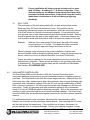
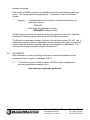
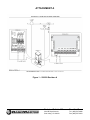
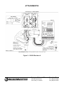
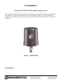
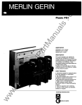
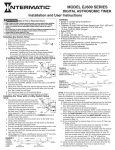
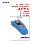
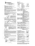
Technical Bulletin
Bulletin No.
Subject:
Page 1 of 7
Product Applicability:
Engineering Release:
Engineering Release Date:
Distribution:
1.0
025 Rev C
Transient Protection
All Rain Master Controllers
R. A. Olson
July 20, 2006
APPROVED FOR GENERAL RELEASE
INTRODUCTION
This Technical Bulletin provides a procedure for the proper installation of the controller
and a summary of the transient protection options available on Rain Master Irrigation
controllers.
Lightning is a high voltage/high current electrical discharge made up of a broad range of
frequencies. It follows the path of least impedance, not the path of least resistance. Fifty
percent of all lightning strikes will have a first strike level of 18kA (18,000 Amps).
Subsequent strikes will be less, about half. Three strikes is the average per lightning
strike. Although theoretically possible, it is economically unfeasible to protect a controller
against a direct strike. The cost of the protection would be prohibitive. Lightning induced
transients, on the other hand, are electrical impulses induced in a conductor by being in
the vicinity of a lightning strike. It is these potentially harmful voltages and currents that
Rain Master has attempted to suppress. The closer the strike to the equipment, and the
longer the attached conductors (AC line and field wiring), the larger the induced transient
will be.
The voltage from a lightning strike rises very fast, typically to its peak in a few millionths
of a second. This energy must be returned to earth as quickly as possible, through a low
impedance path. At this speed, the impedance of the ground system is much more
important than its DC resistance. Impedance in the ground system is reduced by
increasing the surface area of the conductors and decreasing their length. The buildup of
electrons on the ground system also must be dissipated to prevent dangerous voltages in
the equipment. The ground system must therefore be of sufficient size to absorb the
energy.
2.0
TRANSIENT PROTECTION
In order to be rendered harmless, an induced transient must be returned to earth ground
before harmful energy can enter the equipment. The protection components
incorporated in the Rain Master controllers rely completely on the external ground path
provided during the installation of the controller.
Technical Bulletin 025
Sheet 1 of 7
3910-B Royal Avenue
Simi Valley, CA 93063
Tel: (805) 527-4498
Fax: (805) 527-2813
NOTE:
IT IS ABSOLUTELY IMPERATIVE THAT A GOOD GROUNDING
SYSTEM BE INSTALLED.
Grounding circuits for Irrigation Systems consist of ground rods, ground plates, copper
strips, straps and solid copper wire. With electro-mechanical equipment, ground rods
provide adequate safety and protection. Ground plates, both alone or in conjunction with
ground rods, should be used to protect electronic equipment, because ground plates
exhibit low inductance/impedance characteristics and therefore are better suited for
protection of electronic equipment. The ground system will consist of one or more
properly installed ground rods, or plates, connected through appropriately sized wire to
the controller. This is described in detail in each Controller’s User Manual.
The safety (green wire) ground from the electrical service is NOT suitable for a lightning
ground. The small wire size, long length, and questionable connections make it
unsuitable for protection against transients. The only acceptable grounding method for
lightning protection is a properly installed and connected ground rod/plate system.
3.0
IMPLEMENTATION
A single 8 foot copper clad ground rod, properly installed, is usually sufficient. The rod
must extend beyond the frost line if possible. The rod should be driven in, not installed in
an augured hole. You may core through a concrete pad or foundation. It should be
located as close as possible to the controller, so that the AWG #6 ground wire is as short
and direct as possible, free of nicks and bends. The ground clamp inside the controller
should be used as the ground point. Be sure to remove any oxide from the copper clad
rod before attaching the ground clamp to the rod. Be sure all connections are solid and
secure.
Should the 8 foot grounding rod not penetrate completely into the soil it is acceptable to
put it into the ground on a slight angle of not more than 45° relative to the vertical
position. It is important that the rod be a full 8 feet into the ground, with only enough of
the rod showing to clamp the wire on.
Circuit impedance is critical to the effectiveness of the ground circuit and cannot be
measured in the field in a practical way. Proper installation is more important to assure
quality results than this measurement. Make sure to meet the minimum requirements of
the NEC (National Electric Code), which are;
a)
b)
A resistance reading of no more than 25 ohms.
A two electrode ground grid.
For installations that require multiple equipment locations, the resistance measurements
of the ground circuits should be compared for consistent readings. Large discrepancies
in the readings allude to different soil conditions, soils with different moisture content, or
improper installation.
Technical Bulletin 025
Sheet 2 of 7
3910-B Royal Avenue
Simi Valley, CA 93063
Tel: (805) 527-4498
Fax: (805) 527-2813
NOTE:
3.1
Proper installation will show a ground resistance of no more
than 25 Ohms. A reading of 5 – 10 Ohms is desirable. If the
desired results are not obtained, then replace the clamps with
permanent welded connections. Solder shall never be used to
make these connections as it will melt during a lightning
discharge.
SOIL TYPES
The conductivity of the soil varies greatly with soil type and moisture content.
Sand may have 100 times the resistance of clay. Soil resistivity can be
significantly reduced with proper soil amendments, which are commonly referred
to as Earth contact or Ground enhancement materials. In low conductivity soil,
such as sand, two or three interconnected ground rods should be used. Spacing
should be greater than the sum of their lengths apart. Connection between the
rods should be made with strap, with a width of at least one percent of its length.
Example:
With two 8 foot rods spaced 20 feet apart, the width of the strap
should be about 2-1/2 inches. The straps should be connected
to the rods with approved clamps and buried in the soil.
Where extremely rocky soil prevents the proper installation of driven rods,
horizontal radials make an excellent lightning ground. Using #10 gauge wires just
buried, install four or more in different directions for at least 50 feet each.
Proper grounding is essential for the surge suppression circuitry to work on any
manufacturer’s controller. Please ground according to the grounding instructions
in Attachment B. The ground rod and clamp can be ordered from Rain Master.
Part Number: EV-GROUND-ROD
4.0
RAIN MASTER CONTROLLERS
The Rain Master RME and the Evolution DX2 with Transient Protection Option
incorporate additional components to provide increased protection for lightning induced
transients. The Rain Master controllers have three stage protection. Observed from the
field wiring side, where transients may enter the equipment, there is a gas discharge tube
suppressor with a breakdown voltage of 90 volts DC, and a surge current rating of 20kA.
Next, a series of inductors of 100 micro-henries provides high impedance to the fast rise
time pulses. Finally, a high speed solid state transient suppressor with a breakdown
rating of 56 volts at 1000A absorbs the remaining transients. Both of the suppressors are
returned to earth ground through the circuit board mounting hardware. The output triacs
are rated at 400 volts and are protected against transient turn-on with a resistor-capacitor
network.
For additional protection in the off season, disconnect the interconnecting cables
between the controller and the lightning protection boards. Disconnecting the AC power
will also help protect the transformer. If the controller has a battery, disconnect it to
prevent damage, due to complete discharge. Record your watering programs for easy
Technical Bulletin 025
Sheet 3 of 7
3910-B Royal Avenue
Simi Valley, CA 93063
Tel: (805) 527-4498
Fax: (805) 527-2813
startup in the spring.
All Evolution and RME controllers are available with a heavy duty lightning and surge
option. This can be specified by appending a “T” (transient) to the controller part
number.
Example:
A standard wall mount 24 station controller without heavy duty
lightning and surge:
DX24-WM
With heavy duty lightning and surge:
DX24-WMT (transient version)
All field wiring connections are made the same way regardless of the option specified.
Attachment A shows a typical output board, with illustrated connections.
The Evolution system has a number of devices to protect the incoming 120 VAC line. If
additional protection is desired, Rain Master can recommend a third party device which
mounts inside the Evolution controller and can be purchased from Rain Master. The
device and mounting information is found in Attachment C.
5.0
DOCUMENTS
More information on earth grounding of electronic equipment is available from the
American Society of Irrigation Consultants (ASIC).
5.1
For the latest revision of ASIC Guideline 100-2002 and the supplemental
grounding specification drawings, go to;
http://www.asic.org/design_guides.htm
Technical Bulletin 025
Sheet 4 of 7
3910-B Royal Avenue
Simi Valley, CA 93063
Tel: (805) 527-4498
Fax: (805) 527-2813
ATTACHMENT A
Figure 1 – 500509 Revision A
Technical Bulletin 025
Sheet 5 of 7
3910-B Royal Avenue
Simi Valley, CA 93063
Tel: (805) 527-4498
Fax: (805) 527-2813
ATTACHMENT B
Figure 2 – 500508 Revision A
Technical Bulletin 025
Sheet 6 of 7
3910-B Royal Avenue
Simi Valley, CA 93063
Tel: (805) 527-4498
Fax: (805) 527-2813
ATTACHMENT C
Intermatic® AG2401C-IND Secondary Surge Arrester
The Intermatic® AG2401C-IND Secondary Surge Arrester protects electrical and electronic equipment
from transient voltage surges which can enter via the main power supply line. It is designed to be
"hardwired" into power circuitry and mounts easily on the irrigation controller power box. This is a UL
listed device.
Figure 3 – AG2401C-IND
End of Bulletin
Technical Bulletin 025
Sheet 7 of 7
3910-B Royal Avenue
Simi Valley, CA 93063
Tel: (805) 527-4498
Fax: (805) 527-2813