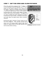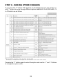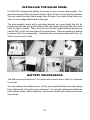
1
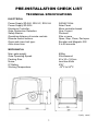
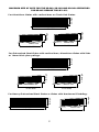
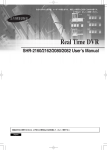
installation manual
FOR
SD series 24V Sliding Gate Operators
Contents
pre-installation check list . . . . . .
1
technical specifications . . . . . . . . . . . . . . . . . . . . . . . 1
maximum size of gate . . . . . . . . . . . . . . . . . . . . . . . . . 2
gate operator frequency of use . . . . . . . . . . . . . . . . . .
3
important safety instructions! . . . . . . . . . . . . . . . . . . .
4
tools and hardware required . . . . . . . . . . . . . . . . . . . . 5
preparing the gate . . . . . . . . . . . . . . . . . . . . . . . . .
6
Guide Post clearance . . . . . . . . . . . . . . . . . . . . . . . .
6
automatic operator fitting requirements . . . . . . . . . . . . . . 7
accessories that can be added . . . . . . . . . . . . . . . . . . .
8
safety photocell
8
digital keypad and/or intercom
9
a Ground Loop vehicle Detector
9
Cabling Requirements . . . . . . . . . . . . . . . . . . . . . . . . . 10
Basic Cabling Guide
10
Full Cabling Guide
10
type and size of Cable
11
how it works . . . . . . . . . . . . . . . . . . . . . . . . . . . . . 12
installation . . . . . . . . . . . .
13
step 1 - install cabling . . . . . . . . . . . . . . . . . . . . . . .
Tips for running low voltage cable yourself.
step 2 - fIT THE OPERATOR . . . . . . . . . . . . . . . . . . . . . .
Position of the Operator
check height of the Operator
raisE the height of the Operator IF NEEDED
fiX the Operator IN PLACE
manually release the Operator
step 3 - fIT THE RACK TO THE GATE . . . . . . . . . . . . . . . . . . .
step 4 - power operator uP . . . . . . . . . . . . . . . . . . . . .
wiring diagram for power connections
checking the gate direction
wiring diagram for the battery
wiring diagram for a photocell
wiring diagram for digital keypad or press button
WIRING DIAGRAM FOR AN INTERCOM
terminating ground loop vehicle detector
terminating a 7-Day timer, digital keypad or keyswitch
terminating an intercom
step 5 - activating the remote controls . . . . . . . . . . . . . .
step 6 - setting the open and close limit . . . . . . . . . . . . . .
Step 7 - set the ramp down position . . . . . . . . . . . . . . . . .
Step 8 - making other changes . . . . . . . . . . . . . . . . . . .
installing the solar panel . . . . . . . . . . . . . . . . . . . .
what happens if there is a power cut? . . . . . . . . . . . . . .
accessories . . . . . . . . . . . . . . . . . . . . . . . . . . . .
trouble shooting . . . . . . . . . . . . . . . . . . . . . . . . . .
warranty . . . . . . . . . . . . . . . . . . . . . . . . . . . . . .
13
14
14
13
15
15
16
16
.17
21
21
22
23
24
24
25
24
25
25
26
27
28
29
30
31
32
32
33
pre-installation check list
technical specifications
Electrical
Power Supply SD-240, SD-LVC, SD-LVH:
240VAC 50Hz
Power Supply SD-SOL:Solar Panel
Electronic Controller:Micro-controller based
Gate Obstruction Detection:Over Current
Safety Barrier:Photocell
Operating distance of remote controls
50m or more
Remote control buttons:Open, Stop, Close, Ped open
Open and close limit type:Encoder and Magnetic SW
Auto-close time:
0 to 99 seconds
mechanical
Max. gate weight:800kg
Gate Operating Speed:22cm/second
Packing Size:
40 x 30 x 18.5cm
Noise:less than 65db
IP Rating:IP57
Working Temperature:-15OC to 55OC
1
maximum size of gate for the SD-240, SD-lvh and SD-sol operators
for SD-LVC reduce this by 40%
2m High
For Aluminium Gates with vertical bars or Chain Link Gates:
1.8m High
1.8m High
to 20m Wide
500mm rise
300mm rise
to 3m Wide
to 6m Wide
2m High
For Galvanised Steel Gates with vertical bars, Aluminium Gates with Slats
or 16mm thick pine palings:
1.8m High
1.8m High
to 10m Wide
400mm rise
200mm rise
to 3m Wide
to 6m Wide
2m High
1.8m High
For Heavy Galvanised Steel Gates or Gates with Hardwood Cladding:
100mm rise
to 6m Wide
4m Wide
2
gate operator frequency of use
This Gate Operator is rated for Residential and light industrial Use
Only, which is a maximum of Five Households or Ten Carpark spaces for a
commercial building. Any more than this and the life span of the operator can
be reduced.
The warrantee does not cover wear and tear due to average use of more
than 60 operations per day.
If higher frequency of use is required consider using an industrial sliding gate
operator rated for continuous use. Gates that have a lot of users are more likely
to be struck by a vehicle so need to be a robust industrial grade operator.
Battery Back Up System
If a Battery Back Up is used the 24V 7Ah battery takes over if the mains power
fails. It will provide up to 200 operations over a couple of days or last a week
or so if not used.
Battery Conditioning During Normal Use
During normal use when the motor starts up it draws power from the battery,
which keeps it conditioned for reliable operation as batteries need to be used
regularly for them to work properly.
Low Voltage Power Cable
The Battery Conditioning arrangment also allows the power transformer to be
away from the gate and Low Voltage Power Cable only run to the gate. This is
because any current that is too high for the low voltage cable is taken up by the
battery. This means that the operator must have a battery connected before
it will work properly with Low Voltage cabling.
Solar Powered
Run from the Battery during normal use, which is charged from a solar panel.
The 14Ah battery supplied will run for up to 12 to 24 operations per day depending on the weight of the gate for 10 cloudy days in a row. A 20Watt Solar panel
will charge the battery from flat in two days of full sun. If you are in an area that
doesn’t get a lot of sun you may need to add extra solar panels and batteries,
which are available as extra’s.
3
important safety instructions!
CONSIDERING THE GENERAL PUBLIC:
When Installing an Automatic Gate that will be entered from a public road
way, make sure the Gate is placed far enough from the road to prevent traffic
congestion.
The Gate must be installed in a location that provides adequate clearance
between it and adjacent structures when opening and closing to reduce risk of
entrapment.
Install the Gate Operator on the inside of the property and fence line. DO NOT
install an opener on the outside of the gate where the public has access to it.
The Gate and Gate Operator must comply with any applicable local council
regulations.
CONSIDERING THE USERS:
If using the Auto-close feature it is highly recommended that a Point to Point
Photo Electric Safety Beam (Photocell) is installed to prevent the gate closing
on any vehicle using the gate.
It is also recommended that a seperate small side gate is used for pedestrians
particularly if there will be children, disabled or elderly people using the gate.
If push buttons, key switches or Digital Keypads are installed, they should be
within sight of the gate but not placed so the user will be tempted to reach
through the gate to activate the gate operator.
USER AWARENESS:
It is important to make sure everyone that will be using the gate is aware of the
following dangers associated with automatic Gates: do not contact any part of
the gate or walk in the path of the gate while it is moving. Never let children
play with the gate controls. Do not attempt to “beat the gate” while it is closing.
This is extremely dangerous.
In the event you sell the property, make sure the new owners have a copy of
these instructions. If you lose the instructions they can be downloaded from:
www.grantsautomation.com.au.
4
tools and hardware required
The tools you’ll need include:
A basic set of hand tools will be needed including: side cutters, pliers, wire
strippers, a range of phillips head screw drivers, a small flat head screw driver
for terminal block screws and a socket set.
You’ll also need a tape measure, marking pen, an elecric drill with hammer
action and variable speed control, a 10mm hammer drill bit and socket bit for
10mm or 3/8” tek screws. An angle grinder is also handy although a hacksaw
will do if you don’t have one.
If you intend on doing you own low voltage cabling a pair of conduit cutters
are handy although a hacksaw can also be used. If you wish to run cabling
across the driveway you will need either a 230mm angle grinder with masonary
grinding disc or a hand held concrete cutter. You can hire these if necessary.
If you’ll be running cabling across a lawn or garden you’ll need a spade and
mattock for digging a low trench. If it’s a long run then a small trench digger can
be hired to do the job.
YOU MAY ALSO NEED THESE ITEMS BEFORE INSTALLATION
For Battery Powered Systems and systems with accessories added Low
Voltage Cable is required between the Transformer and the Gate operator
see “Cabling Requirements” for more information.
You may also need conduit, which is available from Electrical trade
suppliers and hardware stores.
For Mains Powered Systems you will need a mains power point mounted on a
free standing post in front of the gate next to the automatic operator. Check with
local regulations before installing a mains voltage power point yourself, you may
need a registered electrician to do this for you.
5
preparing the gate
Guide must
move easily for
entire length of
gate.
Power Point (if
used) on free
standing post in
front of the gate
Keeper to be
aligned to the
gate correctly
Open
Hard Stop
required
to set gate
open limit
Gate must be Straight
not twisted or bowed.
Gate Track must be Straight,
gate should not run or catch
on the track.
Gate Operator on a
level concrete pad
Make sure that the gate has been properly installed, is straight and slides freely
throughout its entire length without any grabbing from the guides or track any
where along the gate. The gate track must be in a straight line
any sudden dips or rises may prevent the gate operator from working properly.
Repair or replace all worn or damaged gate hardware prior to installation. Gate
posts less than 150mm wide should be made from steel not timber. Replace
posts where necessary. A freely moving gate will require less force to operate
and will enhance the performance of the operator and give a long working life.
The operator should be well drained and not be submersed in water or have
water running past it in heavy rain.
Guide Post clearance
If using a guide post behind a gate
allow at least 60mm clearance for
the Rack. If the guide is fitted to the
front Fence or Wall the clearence
has no effect so long as the Gate
does not contact it at all.
Front
Fence or
Wall
Rear
Guide Post
if used
Gate
60mm
6
automatic operator fitting requirements
Driveway
Guide
Post if used
Extra Gate Length
for Automatic
Operator
300mm
Lawn or Garden
Front Fence/Wall
Gate
Concrete Footing and Pad
Concrete 250mm
Pad
400mm
Gate
Operator
Conduit for Power Cable to
come out of concrete pad here
if Power is Hardwired.
200mm
Driveway
Lawn or Garden
Concrete Pad
400mm
Plan View
The Gate Operator requires a level concrete pad to mount on. Even if the driveway is sloping the
concrete pad for the Operator MUST BE LEVEL!. The concrete pad should be no less than 100mm
thick and after concrete is poured must be given a week or so to harden before the operator is
installed.
If the Gate Operator power is to be hard wired it’s a good idea to place a piece of conduit into the
concrete pad, during installation, for the power cabling later on.
Extra Gate
Length for
Automatic
Operator
need only be the
bottom rail
front VIEW
Gate track and footing must
be straight but can be on a
gentle slope
Gate
Driveway
Concrete Pad must be level
even if gate track isn’t
7
Concrete Pad must be well
drained and not ever be sitting
in water even after heavy rain
accessories that can be added
safety photocell
Photocells are a safety device that prevent the gate from closing on a vehicle.
They are highly recommended if using the Auto-close feature, as the gate
may close at any time.
A Photocell consists of an Invisible Low Power Infrared point to point Beam
Transmitted from one side of a gate to the other. REFLECTOR BEAMS are
NOT recommended for outdoors.
A Photocell prevents a Gate from Closing on a car
If the Photocell’s beam is interrupted by a vehicle, the gate won’t close.
8
digital keypad and/or intercom
To allow access to visitors or tradesman any brand of digital keypad and/or
intercom can be installed (provided the intercom has a door release feature).
A Digital Keypad allows access to An Intercom allows visitors to call the
house and speak with the occupier. If
anyone with the correct pin number.
the occupier wishes to let the visitor in
they can do so by pressing a button on
the intercom to open the gate.
9
Cabling Requirements
Basic Cabling Guide
Open Direction
Gate Operator
To Power
Source
Full Cabling Guide Right hand gate
Intercom
Digital Keypad
Photocell
Gate Operator
To Power
Source
To Intercom Inside
station
Digital Keypad,Keyswitch
or Press Button
The Gate Operator will be on the other side for a left hand gate. If power source
is 240VAC Mains the cable for this should be kept at least 100mm away from
any low voltage cabling.
10
type and size of Cable
240V Mains at Gate
Mains power is best hard wired to the operator. If an outdoor power point is
used the can be turned off so is NOT recommended. You will need a registered
electrician to do this for you.
Low Voltage Systems
Don’t need a register electrican because all power at the gate is 24V. A plug in
transformer is supplied that can plug in anywhere there is power or can be hard
wired by an electrician. Low Voltage Garden Lighting Cable only is required
between the transformer and the gate operator. 2mm2 cable is good for up to
25m and 4mm2 for up to 50m.
For Accessories
0.4mm Diameter (0.12mm2) or 0.65mm Diameter (0.33mm2) Outdoor telephone
cable is ideal for Connecting Photocells, Digital Keypads and Intercoms as this
cable has a tough outer sheath and is gel filled to protect it from moisture. Cat
5 and indoor phone cable is fine to use so long as it isn’t exposed to moisture
for prolonged periods. If using security cable this must be a conduit that is fully
sealed to prevent any exposure to moisture other wise it can rot in the ground.
11
how it works
The SD series Gate Operator consists of an electro-mechanical drive unit with
built in Electronic Controls.
Gear
Wheel
from Operator
drives Rack on
Gate
When the operator is activated by remote control or other device, it drives the
gate open or closed by way of a toothed rack fitted to the gate that engages
with a Gear Wheel on the operator. Magnets are fitted to the rack to set the
open and close limit of the gate, which is detected by a sensor in the operator.
A built in encoder sensors the distance the gate is travelled accurately controlling the ramp up and ramp down of the motor speed and the open and close
limits.
12
installation
step 1 - install cabling
Always get a registered electrician to install any 240V mains voltage cabling for
you other wise any cable for voltage lower than 32VAC or 50VDC you can do
your self without a license.
If your gate track is hollow you can run low voltage cabling through this but
be carefull that the cable doesn’t doesn’t get pinced anywhere along the track
particularly when a vehicle drives over it. If you need to run Low Voltage Cable
across a concrete or bitumen driveway or path you can do this by chasing a
groove with a 9” angle grinder with a diamond cutting blade fitted. Make the
groove deep enough so there is 5mm or so space above the cable when installed and wide enough so the cable sits loosly in the groove. Use an expansion gap where possible as this requires less work. Make sure the cable will not
be pinched if between two slabs of concrete that can shift with ground movement.
Fix the cable into the groove using clear plumbers silicon (non acidic) or other
flexible sealer in the clean groove before the cable and again after, making sure
it sticks to both sides of the groove. If the path or driveway has lawn or garden
edges make sure the cable isn’t exposed or accessable to edge trimmers or
spades by running the groove down the edge and into conduit just under the
edge of the driveway. You’ll need to dig a hole next to the driveway to do this.
Cable run in groove cut in concrete with
silicon top and bottom
If lawn or garden edge, run groove
down edge of concrete
Conduit runs under Path to
keep it safe
Dig hole at edge of concrete
If the driveway meets a post and you need to go around it then chase a groove
where you can with the angle grinder then use a rotary hammer drill as a mini
jack hammer for the corners and fiddly bits.
13
Tips for running low voltage cable yourself.
Always use conduit if running cable in grass, open ground, gardens or
pebbles. Grey conduit is best.
Conduit should be buried deep enough so it is out of harms way. For
existing lawns, pebbled areas or if run along side a driveway then buried
just below the surface is fine. For open ground, gardens and area’s where
there is likey to be other digging going on then conduit should be buried at
least 300mm deep.
Never make joints in cable directly in the ground. If you must join cable,
either bring it up well above the ground and have the joint protected from
the elements by a weather proof junction box or put a pit in the ground
to make sure the joint is sitting in the air within the pit and cannot be
submerged in water.
step 2 - fIT THE OPERATOR
Position of the Operator
60mm from back
face of gate
Gap must
not vary
more
than
5mm as
gate
open and
closes
Place the Operator on it’s concrete pad 60mm from the back face of the gate
then open and close the gate checking that this distance does not vary more
the 5mm each way as you go, other wise the gate and/or track is not straight
enough and the gear wheel may not contact the rack well enough.
14
check height of the Operator
With the Operator sitting on it’s concrete
pad (not fixed in place yet), place a
length of rack on the gear wheel and
check its alignment with the bottom rail
of the gate.
If the mounting holes for the rack are
below the bottom edge of the gate,
then the Operator will need to be
raised up.
raisE the height of the Operator IF NEEDED
Raising the Height of the operator can
be done with a couple of short lengths
of box section or make up a mounting
frame out of box section.
15
There are holes in the bottom of the
operator for attaching a mounting
frame.
fiX the Operator IN PLACE
Fix the Operator to it’s Concrete Pad using M10 x 50mm Dyna bolts or longer
if the Operators height had to be raised. Use galvanised Dyna bolts if you can
so they won’t rust. Large raw plugs and galvanised screws may also be used
if prefered. The important thing is, once the Operator is fitted, it doesn’t work
loose.
manually release the Operator
Put key in and rotate 90O clockwise. Then put allen key in and rotate that 90O
clockwise
16
step 3 - fIT THE RACK TO THE GATE
Before fitting any rack, lay it out in front of the closed gate to see how it lines
up. Start at the operator end, with the first length sitting on the operators gear
wheel, adjusting the position of the rack as you go to make sure the mounting
lugs miss the wheels. If the last length needs to be cut shorter, it must have at
least two mounting lugs attached to the gate.
1) Start with the first length overlapping the
Gear wheel by 100mm, mark this position,
then add more lengths until the end is
reached.
2) Make sure mounting
lugs miss the wheels
3) Last length of rack may need to be cut shorter,
if so it must have at least two mounting lugs on
the gate. If this isn’t possible then all the rack
may need to be moved back a bit and the first
length may also need to be cut.
4) Mark on the gate where the last
length will finish (after cutting).
OPEN FULLY
5) Fully Open the Gate by hand
and using the end mark check the
rack still contacts the Gear Wheel
on the operator, if not it will need to
be adjusted.
This gate operator has no magnet for the open limit so the rack can go right to
the very end when the gate is open.
17
Tek Screw in
centre of slot
To fit the Rack, start with the gate nearly closed and place the first length of rack
on the Operators Gear Wheel, in line with the mark you made earlier and the
bottom rail. Drill 10mm (or 3/8”) Tek screws into two of the mounting lugs for the
rack, making sure they are both in the centre of each slot. Do not fully tighten
at this stage, as the height of the rack needs to be adjusted.
1mm
Move the gate by hand until each of the Tek screws is close to the gear wheel
and adjust the height of the rack until it has about 1mm clearance above the
gear wheel. Tighten the tek screws fully once the height is correct.
18
2nd Length Slotted
into the first
Drill Tek screw in on
an angle to close gap
between lengths of rack
Now fit the 2nd length of rack by sliding the gate open a bit further and placing
it so one end is slotted into the first length and the other end is sitting on the
operators gear wheel, allowing enough room to drill another tek screw in. Drill
the tek screw in on an angle to close up any gap between the two lengths.
Should Run Smoothly over the joint between lengths of rack
If the gate is now moved by hand and run over the join between the lengths of
rack, there should be no jump, it should run smoothly over the join. Also set the
1mm clearance at the new tek screw position and tighen it up fully. Repeat the
same with the remaining lengths of rack, just tacking them all in place for now
with two tek screws.
19
Once all lengths are tacked in place and the gate is opened and closed to
check the rack contacts the gear wheel at all times then cut off any access rack
using an angle grinder or hack saw. The Rack may be plastic on the outside
but it has a steel rod in the middle.
Now go through and tek screw all mounting lugs for the rack that haven’t
been done yet, adjusting the 1mm clearance from the gear wheel as you go. It
is quicker to do these all in one run.
20
step 4 - powering operator up
For the SD version with out a battery simply plug it into a power point and turn
on the power switch to power it up. For versions with a battery back up connect
the battery first then plug the power in or connect the solar panel.
A battery back up can be added to an SD Operator that doesn’t have one at any
time. The SD with a Low Voltage Option must have a battery back up before it
will work properly.
Solar power gate operators can be connected to mains power after installation
if you wanted.
LED Remote Control Input
LED Power
Programming Press Buttons
LED Close
LED Open
24VAC
110V or 240V Switch
240/110AC in 240/110VAC Flashing Light
2 digital display
Battery Back up
Solar Panel
0-110V-240V Transformer (not used with solar)
21
Motor
Power Switch Control and Accessory terminals
Buzzer DC Flashing Light
wiring diagram for motor connections
24V+
GND
15V+
(reg)
checking the gate direction
The Gate Operator is prewired for a Right Hand Gate.
OPEN DIRECTION
RIGHT HAND GATE
If you have a Left Hand Gate then you’ll need to change the Motor Direction
OPEN DIRECTION
LEFT HAND GATE
SD Control Board
For Right Hand Gates change the Motor wires around
so the gate will travel in the opposite direction.
22
Motor
wiring diagram for battery BACK UP
SD Control Board
+
24V AC
charge
transformer or
Solar Panel
_
BLACK
RED
10A Fuse
- +
WARNING!
The Battery cables
MUST BE CONNECTED
THE RIGHT WAY
AROUND!
if not you may damage the
control board.
12V GEL Battery
- +
12V GEL Battery
23
wiring diagram for a photocell
Safety Photocells are used to prevent the gate from closing on a vehicle. The
gate will not close if the photocells light beam is broken. If a photocells light
beam is broken while the gate is closing, the gate will reverse back open until
the photocell is clear then the gate will close normally.
Control and Accessories Terminal of the SD Control Board
Photocell
Transmitter
GND
V+
Photocell
Receiver
GND
V+
COM
N.O.
N.C.
For Solar Powered SD Operators the power for the photocell should come from
the DC Flashing light output so it is only present when the gate is operating
LED Close
LED Open
Motor
Buzzer
DC Flashing Light Output
Photocell
Receiver
GND
V+
COM
N.O.
N.C.
24V+
GND
15V+
(reg)
24
Photocell
Transmitter
GND
V+
wiring diagram for an intercom
Intercoms with a lock output can also be used to activate an automatic gate.
Intercoms will either have a clean contact output that can be used as it is or a
12VAC or 12VDC output for an electric lock, which requires an optional adaptor.
Control and Accessories Terminal of the SD Control Board
INTERCOM WITH
12VAC or 12VDC
OUTPUT
for Electric Lock
~+
RLY-12V
Adaptor
V~+
GND.
COM
N.O.
N.C.
INTERCOM
WITH CLEAN
COM CONTACT
N.O. OUTPUT
N.C.
For Solar Powered Operators If an intercom is
powered from the gate operator extra solar panels
and batteries are required to allow for extra current
draw
wiring diagram for a digital keypad or press button
A Digital Keypad or Press Button can be used to activate the gate.
Control and Accessories Terminal of the SD Control Board
Digital
Keypad
Press
Button
GND
V+
COM
N.O.
N.C.
For Solar powered operators if a keypad is powered from the gate operator extra solar panels and batteries are required to allow for extra current draw.
25
step 5 - activating the remote controls
Press the “F” button until “FF” appears on the
display flashing, then release the “F” button
and press any button on the remote control until the “FF” stops flashing and the remote control is activated.
You can activate up to 50 remote controls
Once activated the remote control has on button to open, one to close, one to stop and one
for pedestrian entry that opens the gate only
part way for pedestrians.
Deactivating Remote Controls
Press the “Enter” button until the display lights up, whcih takes about 1 second
then all remote controls have been deactivated.
You can’t deactivate them one at a time only all at once.
26
step 6 - setting the OPEN AND close limit
There are two magnets to be fitted to the rack, which set the open and close
limits of the gate. The height of the magnet determines whether it is for open
or close.
Close Magnet is higher
Open magnet is lower
Rack
Side View
Fit the open magnet to the close end of the gate so it lines up with the sensor
inside the SD Operator when the gate is opened. Then repeat the same with
the close magnet on the open end of the gate.
Once the ramp down positions are set (next step) you may find the gate doesn’t
open or close enough. You can correct this by moving the position of the magnet and you may need to reset the ramp down postions after you have done
this.
Top View
Magnetic sensor inside SD Operator
27
Step 7 - set the open and close distance
Close the gate fully and press the “+” button on
the circuit board in the SD Operator until “FF” appears on the display flashing, then release the
“F” button. Now on a remote control press the
“P” button followed by the “Open” button together
holding them both until the gate begins to open
slowly, then let go of the buttons. The gate will
run until it reaches the open magnet so it learns
the distance it has to travel. It needs to know this
so it can ramp the speed down when normally
opening.
Repeat the same using the “Close” button to set
the close distance. The operator should now
ramp up to full speed when opened and slow
down as it approches the fully open position and
do the same when closing.
28
Step 8 - making other Changes
If you press the “F” button “A0” appears on the display and you can use the “+”
and “-” buttons to cycle through different options labelled A1 to A8, B0 to B2, C0
to C9 which are as follow:
Pressing the “F” button again to select the option and use the “+” and “-” Buttons
to change the option value.
29
installing the solar panel
For SD-SOL charging the battery is by way of one or more solar panels. It is
important to place the solar panel where it gets full sun for as long as possible.
You can install the solar panel away from the gate if you wish to get more sun
and run low voltage cable back to the gate.
The solar panel(s) come with a mounting bracket, you must install this first by
measuring half way along both sides of the solar panel and mark the hole positions for each bracket. Then drill holes for the two angle brackets being very
carefull NOT to drill into the glass of the solar panel. Place something in behind
to prevent this from happening. Assemble the mounting bracket and then attach it to your post or wall.
battery Maintenance
The Battery should last from 3 to 5 years with normal use or less if it is allowed
to run flat.
You can replace the batteries your self by opening the battery box and unplug
them taking note of how they are connected. You can get replacement batteries
from battery shops, alarm suppliers, electronics shops and auotmotive accessory shops.
30
what happens if there is a power cut?
Battery operated versions will not be effected by a power cut unless it is longer
than a few days. If longer than this the gate should be manually operated and
battery disconnected before it runs flat. Once the power is restored the battery
will recharge. If the battery has been run flat allow over night charging before
using.
When power is first restored if the gate is fully open or closed it will work normally but if power was lost while it was in mid cycle or it was manually released
and left in mid cycle when powered up then once the gate is operated it will run
at a slow speed until it finds the open or close magnet. While it is running at
slow speed if you hold the open or close remote control button down the gate
will ramp up to full speed and if you release the button it will ramp down to slow
speed again, which is a feature purely for speeding up the process.
31
accessories
TX-4 Extra Remote Controls for either 433.92Mhz (Blue) or 315Mhz (White)
RX-1 Stand alone Receiver - to allow a garage door or another brand of gate operator to be operated with the e-Gate remote control ether 433.92Mhz or 315Mhz.
RX-MegaStand alone receiver for a large number of users allows use of up to 1000 remote controls. A remote control can be deleted even if lost.
ANT-1 Antenna for remote control ether 433.92Mhz or 315Mhz.
Batt-TX Replacement Battery for TX-4 Remote control
Batt-7Ah Replacement Battery for Battery Back up (two required for 24V)
VCB-12Voltage Converter Board 16 to 24VAC/DC in and 12V 500mA out
RLY-12 Relay Board 12VAC/DC in and clean contacts rated at 60VDC/125AC 2A
RLY-24 Relay Board 24VAC/DC in and clean contacts rated at 60VDC/125AC 2A
PC-1 Photocell 12/24VAC/DC 15m outdoor
trouble shooting
Gate runs in the wrong direction - check the motor power wires are correct, if wired the wrong way
around the motor will travel in the wrong direction.
Gate runs for a short distance then stops - check the motor encoder wiring or operator isn’t being
overloaded by a stiff gate.
Operator not working at all - check power cord or battery cable is plugged in. Check there is power
at the gate. Check fuses on the control board.
Gate won’t work when first powered up - check the input cable connections are correct and all accessories that may be connected are working properly.
Remote control range drops some times - most likely caused by interference from some other device in the area using a similar frequency. Installing an external antenna can minimize the effects
of interference.
32
warranty
A 2 Year Back to Base Warranty is offered by Grant’s Automation for any defect in a Gate Operator
System manufactured by Grant’s Automation or any third party component supplier to Grant’s
Automation due to faulty workmanship or materials causing the Operator to fail to work as specified
in this Installation Manual.
Should any fault occur during the first 2 Years after the operator was purchased, it should be returned
to the factory for repair or at the discretion of Grant’s Automation replacement at no charge under
the following conditions:
1. Proof of purchase is required ie. Invoice or purchase details recorded by Grant’s Automation.
2. If an operator is not installed immediately after purchase, at the discretion of Grant’s Automation,
the warranty may be extended to up to a maximum of 2 Years after the date installed.
3. The operator has been installed according to this Installation Manual and Serviced according
to the User Manual.
4. The operator has not been used for a gate larger, of a different type or higher frequency of use
than that specified in this Installation Manual. All gate specifications are required before any
claims will be accepted.
5. The operator hasn’t been used in a highly corrosive environment or has been exposed to
contaminents that could cause the operator to fail.
6. The operator has not been used for purposes other that it was intended for.
7. The operator has not been tampered with or modified by any party not authorised in writing by
Grant’s Automation to do so.
8. The operator has not been damaged by any malicious act, accident, animal infestation or
adverse weather conditions beyond the control of Grant’s Automation.
9. A reasonable amount of care with handling or using the operator has been be taken.
33