1
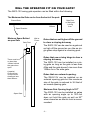
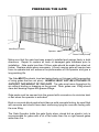
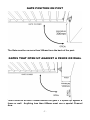
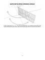
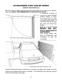
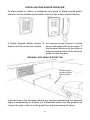
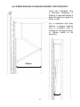
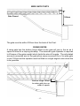
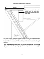
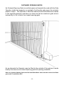
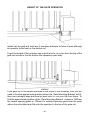
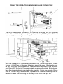
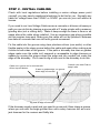
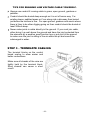
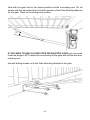
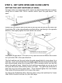
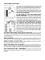
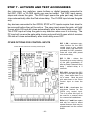
installation manual
FOR
SWG-12V Series
12V Single Swing Gate Operator
Contents
pre-installation check list . . . . . . . 1
maximum size of gate for the SWG-12V . . . . . . . . . . . . . . 1
will the operator fit on your gate? . . . . . . . . . . . . . .
2
gate operator frequency of use . . . . . . . . . . . . . . . . 3
important safety instructions! . . . . . . . . . . . . . . . . . 4
tools and hardware required . . . . . . . . . . . . . . . . .
5
environment suitbale for this operator . . . . . . . . .
5
preparing the gate . . . . . . . . . . . . . . . . . . . . . . . 6
gate position on post . . . . . . . . . . . . . . . . . . . . . . 7
Gates that open up against a fence or wall . . . . . . . . . . . 7
lifting gate for sloping driveway . . . . . . . . . . . . . . . . 8
outward opening gate for sloping driveway . . . . . . . . . . 8
gate with wide opening angle . . . . . . . . . . . . . . . . . . 9
accessories that can be added . . . . . . . . . . . . . . . . . 10
safety photocells
10
digital keypad and/or intercom
11
Ground Loop vehicle Detector
11
Cabling Requirements . . . . . . . . . . . . . . . . . . . . . . 12
Basic Cabling Guide
12
Full Cabling Guide
12
type and size of Cable
13
how it works . . . . . . . . . . . . . . . . . . . . . . . . . . 14
8 steps to installing the SWG-12V . . .
step 1 - fit the operator to the gate post . . . . . . . . . . .
allowing enough clearance behind the open gate
wide gate posts
rising gates
opening angle more than 90O
Outward Opening Gates
the Height of the gate operator
Fixing the operator to the Post
step 2 - install cabling . . . . . . . . . . . . . . . . . . . . .
Tips for running low voltage cable yourself
step 3 - terminate cabling . . . . . . . . . . . . . . . . . . .
SWG-12V-S General Wiring Diagram
terminating The battery and solar panel
terminating an electric lock
terminating a 24VDC or AC LOCK
terminating safety photocells
terminating a light
terminating digital keypad, Key switch or Press Button
terminating ground loop vehicle detector
terminating a 7-Day timer, digital keypad or keyswitch
terminating an intercom
step 4 - tune the Remote Controls in . . . . . . . . . . . . . .
remote control open, stop and manual close
remote control open with auto-close
removing remote controls
remote controlled pedestrian entry
user adding remote control at a later date
step 5 - fit the gate mounting bracket . . . . . . . . . . . . .
Step 6 - Set Gate open and close limits . . . . . . . . . . . . .
setting the limit switches (IF USED)
using hards stops only
Step 7 - activate and test accessories . . . . . . . . . . . . .
other options for control inputs
Step 8 - fine tune gate operator preferences . . . . . . . . .
changing the Auto-close delay
changing the Photocell-close delay
changing the Pedestrian-close delay
changing the Lock/Light Output
changing the ramp time for soft start and soft stop changing the gate obstruction sensitivity
return to factory settings . . . . . . . . . . . . . . . . . .
what if happens if there is a power is cut? . . . . . . . . . . .
accessories available . . . . . . . . . . . . . . . . . . . . .
trouble shooting . . . . . . . . . . . . . . . . . . . . . . .
warranty . . . . . . . . . . . . . . . . . . . . . . . . . . . .
15
15
16
17
17
18
19
20
21
22
23
23
24
25
26
26
27
27
28
28
29
29
30
30
30
31
31
31
32
34
34
35
36
36
. 37
37
37
38
38
39
39
40
40
41
42
43
pre-installation check list
maximum size of gate for the SWG-12V
If this Operator is installed on a gate that is too large it may not work properly. Gates that have filled
in cladding are more prone to wind forces so cannot be as wide.
1.2m High
Open Bar Aluminium, Galvanised Steel and Farm Gates:
1.8m High
4m Wide
3.5m Wide
1.2m High
Solid Timber Gates, Gates with sheet metal cladding and Chain Link Gates
in areas with light to moderate wind:
1.8m High
3.5m Wide
3m Wide
Note: Outward opening gates run twices as fast so the relative gates size
is 3/4 that of an inward opening gate.
-1-
will the operator fit on your gate?
The SWG-12V swing gate operator can be fitted within the following:
The Maximum the Gate can be from the back of the post:
Closed Gate
300mm
Gate Post
or Wall gate
is hung
from
Open Direction
Minimum Space Behind
an open Gate
Gate Post
Wall or
Fence
Gates that are set higher off the ground
to clear a sloping driveway
The SWG-12V can be used on a gate set
as high off the ground as you like as single gates stop against a receiving post.
There must be
no less than
140mm behind
the gate when
open.
A special
Channel Arm
is required for
clearence less
than 600mm
Gates that use a rising hinge to clear a
sloping driveway
The SWG-12V can be installed on a rising gate so long as the gate is less than
40kg and the gate doesn’t rise more than
150mm for a 3m wide gate.
Gates that are outward opening.
The SWG-12V can be installed on an
outward opening gate but the maximum
size of the gate is reduced to 3/4 that of
an inward opening gate.
Maximum Gate Opening Angle is 120O
Open Gate
The SWG-12V can be installed on gates
with an opening angle up to 120O but
does not hold the gate as well as 90O
when closed so an electric lock is recommended.
-2-
gate operator frequency of use
This Gate Operator is rated for Residential and light industrial Use
Only, which is a maximum of Five Households or Ten Carpark spaces for a
commercial building. Any more than this and the life span of the operator can
be reduced.
The warrantee does not cover wear and tear due to average use of more
than 60 operations per day.
If higher frequency of use is required consider using an industrial sliding gate
operator rated for continuous use. Gates that have a lot of users are more likely
to be struck by a vehicle so need to be a robust industrial grade operator.
Battery Back Up System
This operator has a 12V 7Ah back up battery as standard that takes over if the
mains power fails. It will provide up to 200 operations over a couple of days or
last a week or so if not used.
Battery Conditioning During Normal Use
During normal use when the motor starts up it draws power from the battery,
which keeps it conditioned for reliable operation as batteries need to be used
regularly for them to work properly.
Low Voltage Power Cable
The Battery Conditioning arrangment also allows the power transformer to be
away from the gate and Low Voltage Power Cable only run to the gate. This is
because any current that is too high for the low voltage cable is taken up by the
battery. This means that the operator must have a battery connected before
it will work properly with Low Voltage cabling.
Solar Powered
Run from the Battery during normal use, which is charged from a solar panel.
The 14Ah battery supplied will run for up to 24 operations per day for 10 cloudy
days in a row. The 20Watt Solar panel will charge the battery from flat in two
days of full sun. If you are in an area that doesn’t get a lot of sun you may need
to add extra solar panels and batteries, which are available as extra’s.
-3-
important safety instructions!
CONSIDERING THE GENERAL PUBLIC:
When Installing an Automatic Gate that will be entered from a public road
way, make sure the Gate is placed far enough from the road to prevent traffic
congestion.
The Gate must be installed in a location that provides adequate clearance
between it and adjacent structures when opening and closing to reduce risk of
entrapment. Swing gates must not open into public access areas!
Install the Gate Operator on the inside of the property and fence line. DO NOT
install an opener on the outside of the gate where the public has access to it.
The Gate and Gate Operator must comply with any applicable local council
regulations.
CONSIDERING THE USERS:
If using the Auto-close feature it is highly recommended that Point to Point
Safety Photocells are installed to prevent the gate closing on any vehicle using
the gate.
It is also recommended that a seperate small side gate is used for pedestrians
particularly if there will be children, disabled or elderly people using the gate.
If push buttons, key switches or Digital Keypads are installed, they should be
within sight of the gate but not placed so the user will be tempted to reach
through the gate to activate the gate operator.
USER AWARE NESS:
It is important to make sure everyone that will be using the gate is aware of the
following dangers associated with automatic Gates: do not contact any part of
the gate or walk in the path of the gate while it is moving. Never let children
play with the gate controls. Do not attempt to “beat the gate” while it is closing.
This is extremely dangerous.
In the event you sell the property, make sure the new owners have a copy of
these instructions. If you lose the instructions they can be downloaded from:
www.grantsautomation.com.au.
-4-
tools and hardware required
The tools you’ll need include:
A basic set of hand tools will be required including: side cutters, pliers, wire
strippers, a range of phillips head screw drivers, a small flat head screw driver
for terminal block screws, a Socket Set or Shifting Spanner.
You’ll also need a Spirit level, tape measure, marking pen, an elecric drill with
hammer action and variable speed control and a selection of drills bits.
If you’re going to be doing your own low voltage cabling a pair of conduit cutters
are handy although a hacksaw can also be used. If you wish to run cabling
across the driveway you will need either a 230mm angle grinder with masonary
grinding disc or a hand held concrete cutter. You can hire these if necessary.
If you’ll be running cabling across a lawn or garden you’ll need a spade and
mattock for digging a low trench. If it’s a long run then a small trench digger can
be hired to do the job.
YOU MAY ALSO NEED THESE ITEMS BEFORE INSTALLATION
For Battery Powered Systems and systems with accessories added Low
Voltage Cable is required between the Transformer and the Gate operator
see “Cabling Requirements” for more information.
You may also need conduit, which is available from Electrical trade
suppliers and hardware stores.
For Mains Powered Systems you will require a power point fitted on the Hinge
side of the gate. Check with local regulations before installing a mains voltage
power point yourself, you may need a registered electrician to do this for you.
environment suitable for operator
The SWG-12V is suitable for outdoor use so long as it is NOT exposed for long
periods to saltly air or other corrosive substance that may cause premature deterioation of components of the gate, gate operator or accessores that may be
connected to the operator.
-5-
preparing the gate
Hard Stop (if used)
Operator
Power Point (if used)
Make sure that the gate has been properly installed and swings freely in both
directions. Repair or replace all worn or damaged gate hardware prior to
installation. Gate posts less than 150mm wide should be made from steel not
timber. Replace posts where necessary. A freely moving gate will require less
force to operate and will enhance the performance of the operator and give a
long working life.
The Gate MUST be plumb, level and swing freely on it hinges (with the exception
of rising gates that are not plum). Wheels must not be attached to
support the weight of the gate. The gate must move throughout its
arc without binding or dragging on the ground. Note: gates over 100kg should
have ball bearing hinges with grease fittings.
Gate posts must be secured into the ground with concrete so to minimize twist
or flex when the operator is activated.
Brick or concrete block posts should have a solid concrete footing, be core filled
with concrete and should have steel reinforcing tying the concrete footing with
the core filling.
The Gate Operator holds the gate firmly when closed but an electric lock is
recommended for gates with a lot of flex wider than 2m or rigid framed gates
wider than 3m.
-6-
gate position on post
The Gate must be no more than 300mm from the back of the post.
Gates that open up against a fence or wall
There must be at least 140mm behind the gate if it opens up against a
fence or wall. Anything less than 600mm must use a special Channel
Arm.
-7-
lifting gate for sloping driveway
For driveways that slope up as you drive in the gate can be lifted so it clears the
ground when it opens. The steeper the driveway the larger the gap under the
gate when it is closed.
outward opening gate for sloping driveway
For driveways that slope up as you drive in the gate can be made to swing
outwards but the gate should be set back so it doesn’t open out onto the street.
The automatic operator should be installed inside of the gate so it won’t be
tampered with.
-8-
gate with wide opening angle
Gates opening up to 120O can be automated but the operator requires more
space behind the gate when open and should also have an electric lock fitted.
-9-
accessories that can be added
safety photocells
Photocells are a safety device that prevent the gate from closing on a vehicle.
They are highly recommended if using Auto-close.
A Photocell consists of
a point to point Invisible
Infrared Beam of Light
Transmitted from one side
of a gate to the other. A
vehicle travelling through
the gate will break the
beam.
REFLE C TOR
BEAMS ARE NOT
RE C OMMENDED
OUTDOORS!
With swing gates two
sets of Photocells are
necessary to get full
coverage.
Photocells prevent Gate Closing on a car
If either Photocells beam is broken by a vehicle, the gate won’t close, until the
vehicle has passed and beam is remade. The Photocell can also be used to
control the closing of the gate.
- 10 -
digital keypad and/or intercom
To allow access to visitors or tradesman any brand of digital keypad and/or
intercom can be installed (provided the intercom has a door release feature).
A Digital Keypad allows access to An Intercom allows visitors to call the
anyone with the correct pin number.
house and speak with the occupier. If
the occupier wishes to let the visitor in
they can press a button on the intercom
inside to open the gate.
Ground Loop vehicle Detector
Ground Loop in
driveway used to
detect vehicles
A ground loop in the driveway detects any vehicles approaching the gate and
opens it automatically to let them out. Pedestrians cannot use the ground loop
to open the gate, which is a safe guard from anyone jumping the fence.
- 11 -
Cabling Requirements
Basic Cabling Guide
To Power Source either
240VAC mains or
15VAC trickle charge
Operator
Full Cabling Guide
Intercom
Digital Keypad
Outer Photocell
Electric Lock
To Intercom Inside station
Inner Photocell
Ground Loop
Digital Keypad, Keyswitch or Press Button
To Power Source either 240Vmains or
15VAC trickle charge
Operator
For a gate swung from the left side the Operator and power cabling will be on
the opposite side. Cable for the electric lock may run in the gate frame. If power
source is hard wired 240VAC Mains this should be kept at least 100mm away
from any low voltage cabling.
- 12 -
type and size of Cable
240V Mains at Gate
Mains power is best hard wired to the operator. If an outdoor power point is
used the can be turned off so is NOT recommended. You will need a registered
electrician to do this for you.
Low Voltage Systems
Don’t need a register electrican because all power at the gate is 12V. A plug in
transformer is supplied that can plug in anywhere there is power or can be hard
wired by an electrician. Low Voltage Garden Lighting Cable only is required
between the transformer and the gate operator. 2mm2 cable is good for up to
50m and 4mm2 for up to 100m.
For Accessories
0.4mm Diameter (0.12mm2) or 0.65mm Diameter (0.33mm2) Outdoor telephone
cable is ideal for Connecting Photocells, Digital Keypads and Intercoms as this
cable has a tough outer sheath and is gel filled to protect it from moisture. Cat
5e and indoor phone cable is fine to use so long as it isn’t exposed to moisture
for prolonged periods. If using security cable this must be a conduit that is fully
sealed to prvent any exposure to moisture.
For an Electric Lock
If the lock is on the gate then use a flexible cable such as Figure 8 (Turrup,
Speaker or Audio cable) or Mains Flex. DO NOT use automotive cable or solid
cored cable such as telephone cable or TPS as this will eventually break. If
the Lock is on the post and the cable must go in the ground then use either
automotive cable, TPS or 0.65mm Dia outdoor telephone cable with the pairs
doubled up.
- 13 -
how it works
The SWG-12V-S Swing Gate Operator consists of an Electro-mechanical
Operator with built in Electronic Controls
Gate Operator with
Built in Electronic
Controls
Gate Mounting Bracket
Connecting Arm
Articulated Arm
As the Articulated
Arm Rotates it pulls
the Gate Open or
pushes it closed
When the Operator is activated by remote
control or other control device, each side
pulls the gate open or pushes it closed (or
vise versa for outward opening gates) with
an articulated arm connected to the gate.
Either limit switches, hard stops or a
combination of both can be used to determine
the open and close limits of the gate. The
electronic controls also continually monitor
the loading on the gate so if it is obstructed it
will reverse direction for safety.
- 14 -
8 steps to installing the SWG-12V
step 1 - fit the operator to the gate post
The Gate Operator must be fitted securely
to the gate post so it doesn’t work loose
over time.
POST
For Gate Posts
less than 140mm
wide use an
angle bracket for
fixing to post.
Operator must be
positioned so the
gate can open
fully
If the post is less than 140mm wide then
then an angle bracket is required to enable
secure fixing.
The Operator must be set far enough
along a post to allow the gate to open
fully.
If the post is angled - particular care
must be taken with the positioning of the
operator so it doesn’t obstruct with the
gate when open.
angled
POST
Gate Open
Operator Set
along post
far enough
so it doesn’t
obstruct with
the gate when
fully open.
Gate Open
- 15 -
allowing enough clearance behind the open gate
Using the Standard Arm
a minimum clearance of
600mm is required behind a
gate that opens up against a
fence or wall.
For a clearance less than
600mm a special channel
arm is available that is
suitable for clearances down
to 140mm (width of the
operator).
600mm
140mm
- 16 -
wide gate posts
Gate Closed
300mm
The gate must be within 300mm from the back of the Post.
rising gates
A rising gate has the bottom hinge offset so the gate will rise in the air as it
opens to allow for a sloping driveway. The automatic gate Operator is required
to lift some of the gates weight which limits the size of the gate. The articulated
arm and connected arm to the gate allow some movement for a 3m wide gate
to rise 150mm but the operator must be fitted on a slight angle to also allow this
to be possible.
Bottom Hinge Offset
to make gate rise up
when it opens
- 17 -
opening angle more than 90O
400mm
Operator needs to be set
further along the gate post
so it doesn’t obstruct with the
open gate.
Gate Open
to 120O
For wider opening angles the operator needs to be set further along the gate
post to prevent it obstructing with the gate when open. The maximum opening
angle is 120O. If necessary a 150mm wide post should be installed for the gate
operator.
Note: Opening Angles wider than 110O are not recommended for Fully Clad
Gates as the wider the opening angle the less torque the motor can apply to
the gate.
- 18 -
Outward Opening Gates
An Outward Opening Gate is one that opens out towards the road with the Gate
Operator inside the property, so instead of pulling the gate open the actuator
pushes it open. The Operator is fitted the same but the articulated arm rotates
in the opposite direction and does run twice as fast so maximum gate size is
reduced by to 3/4 to that of an inward opening gate.
As an alternate the Operator may be fitted to the outside of the gate so it works
exactly the same as an inward opening gate but opening outwards.
Note: for Outward Opening Gates the Red and Black Motor wires must be reversed so Black
goes to ACT+ and Red to ACT-
- 19 -
height of the gate operator
The Operator may connect to any strong horizontal rail of the gate. If on the
middle rail the gate will twist less if someone attempts to force it open although
an operator looks best on the bottom rail.
To get the height of the operator use a spirit level to run a line from the top of the
gate rail across to the the bottom the operators main body.
If the gate rail is not square because of the slope of the driveway, then you will
need to find the approximate position where the ‘Gate Mounting Bracket’ will fit,
then use a straight edge and level or laser level to run your line from there. To
find the approximate position of the ‘Gate Mounting Bracket’ measure 1050mm
for inward opening gates or 750mm for outward opening gates from the point
where the articulated arm fits onto the operator to the top of the gate rail.
- 20 -
Fixing the operators mounting plate to the Post.
The lid of the operator will need to be removed to access the top mounting
holes. It’s best to bolt right through the gate post using M12 Cup Head Bolts so
as to avoid them coming loose over time.
For Core filled Brick or Concrete block posts M16 x 150mm Dyna Bolts, Coach
Screws + Wall Plugs or Chemset fastenings should be used. Brick posts must
be core filled with concrete and the Operator MUST be fixed to the concrete
core filling NOT the brick. If necessary make up a mounting plate. Brick doesn’t
have the physical strength required by the operator. Bricks are normally 90mm
wide so 150mm long Coach Screws, Dyna Bolts or Chemset fastenings will be
needed to reach the core filling. If not they’ll more than likely pull out.
- 21 -
step 2 - install cabling
Check with local regulations before installing a mains voltage power point
yourself, you may need a registered electrician to do this for you. Normally any
cable for voltage lower than 32VAC or 50VDC you can do your self without a
license.
If you need to run Low Voltage Cable across a concrete or bitumen driveway or
path you can do this by chasing a groove with a 9” angle grinder with a masonry
grinding disc (not a cutting disc). Make it deep enough so there is 5mm or so
space above the cable when installed. Use an expansion gap where possible
as this requires less work. Make sure the cable will not be pinched if between
two slabs of concrete that can shift with ground movement.
Fix the cable into the groove using clear plumbers silicon (non acidic) or other
flexible sealer in the clean groove before the cable and again after, making sure
it sticks to both sides of the groove. If the path or driveway has lawn or garden
edges make sure the cable isn’t exposed or accessable to edge trimmers or
spades by running the groove down the edge and into conduit just under the
edge of the driveway. You’ll need to dig a hole next to the driveway to do this.
Cable run in groove cut in concrete with
silicon top and bottom
If lawn or garden edge, run groove
down edge of concrete
Conduit runs under Path to
keep it safe
Dig hole at edge of concrete
If the driveway meets a post and you need to go around it then chase a groove
where you can with the angle grinder then use a rotary hammer drill as a mini
jack hammer for the corners and fiddly bits.
- 22 -
Tips for running low voltage cable yourself.
Always use conduit if running cable in grass, open ground, gardens or
pebbles.
Conduit should be buried deep enough so it is out of harms way. For
existing lawns, pebbled areas or if run along side a driveway then buried
just below the surface is fine. For open ground, gardens and area’s where
there is likey to be other digging going on then conduit should be buried at
least 300mm deep.
Never make joints in cable directly in the ground. If you must join cable,
either bring it up well above the ground and have the joint protected from
the elements by a weather proof junction box or put a pit in the ground
to make sure the joint is sitting in the air within the pit and cannot be
submerged in water.
step 3 - terminate cabling
The terminal blocks on the control
board unplug to allow easier and
better connections.
Make sure all strands of the wire are
tightly held by the terminal block.
Stray strands can cause a short
circuit.
- 23 -
SWG-12V Series General Wiring Diagram
N.O. RELAY
OUT FROM
INTERCOM
or PRESS
BUTTON
OSC P/B
+
ANT
GND
V+
GND.
COM
N.O.
N.C.
OSC
OPEN
STOP
PC
CLS
Digital
Keypad
GND
12V+
PED
GDN
V+
COM
N.O.
N.C.
CTRL-GP-24V-S Control Board
Loop
Detector
GND
V+
COM
N.O.
N.C.
Close Open
(Top) (Bottom)
Limit Switches
if used
Motor 1
has Ped
entry mode
DC IN -
DC IN +
ACT-
ACT+
LOCK LOCK +
Electric
Lock
Close Open
(Top) (Bottom)
Limit Switches
if used
Motor 2 for
DoubleGates
12V Battery
Charge
Regulator
Unit
240VAC
Mains Supply
P N E
Chassis
Ground
Red
Photocell
Transmitter
V+
GND
Black
Photocell
Receiver
GND
V+
COM
N.O.
N.C.
These Shunts must be in place as no
limit switches are used
ACT-
Photocell
Transmitter
V+
GND
Black
Red
Photocell
Receiver
GND
V+
COM
N.O.
N.C.
CLS
COM
OPN
12V Relay
Sheild
ACT+
12V LOCK
OUT FROM
INTERCOM
These Jumper Shunts overide the normally closed inputs, REMOVE
ONLY ONCE GATE LIMITS ARE SET
Learn P/Bs
Learn P/Bs for Refor Limits and
mote Controls
Preferences
Antenna
10A
Diode
12VAC Input
35A Rectifier Unit
12VDC output
240V - 12V 80VA Transformer may be external
- 24 -
+
12V Battery
terminating The battery and Solar Panel
The Battery is wired the same for Mains Powered or Solar although for solar the
charge regulator is on the control board.
e-Gate Control Board
- + - +
Solar Panel
WARNING!
BLACK
The Battery cables
MUST BE CONNECTED
THE RIGHT WAY
AROUND!
if not you may damage the
control board.
RED
10A Fuse
- +
12V GEL Battery
- 25 -
terminating an electric lock
LOCK LOCK +
If fitting a 12VDC Electric Strike Lock or an Electromagnetic Clamp they can be
connected directly to the Control Board. The factory setting for the LOCK/
LIGHT output is for an electric strike lock. See “Setting up the LOCK/LIGHT
output” section for information on how to change this for an electromagnetic
clamp.
Note: Electromagnetic clamps are not suitable for Solar systems as they
draw current continuously and will run the battery flat.
12VDC STRIKE LOCK
OR MAGNETIC CLAMP
V+
GRD
terminating a 24VDC or AC LOCK
If using 24VDC or AC electric lock, there isn’t a suitable source of power
available from the control board so you will need to use a seperate supply and
a relay to get this to work. 2A 12VDC relays are available as an accessory. A
diode should be used with DC Strike Locks or a surge protector should be used
for AC locks. These are usually supplied with the lock.
LOCK -
+
12VDC
Relay
V+
GND.
COM
N.O.
N.C.
LOCK +
POWER
SOURCE
FOR
LOCK
24VDC or AC STRIKE
LOCK or Magnetic
Clamp
V+
GRD
- 26 -
terminating safety photocells
Safety Photocells use a normally closed connection to the control board. If
either photocells light beam is broken by a vehicle while the gate is closing it
will reverse back open again. The gate will not close until the both photocell
light beams are remade and vehicle is clear. If photocell closing delay option
is activated (DIP 3 ON) the gate will begin to close immediately or after the
photocell close delay
PC
GND
12V+
Photocell
Transmitter
V+
GND
Photocell
Receiver
GND
V+
COM
N.O.
N.C.
Photocell
Transmitter
V+
GND
Photocell
Receiver
GND
V+
COM
N.O.
N.C.
Note: Photocells must be
aligned properly other wise
they may prevent the gate
from closing if sunlight is
shining on them or in rainy
weather.
terminating a light
By connecting a 12VDC relay to the gate operator it can also activate lights for
1 or 4 minutes when ever the gate is opened. See “Changing the LOCK/LIGHT
output” section in Step 8 for information on how to change this.
LIGHT -
12VDC
Relay
V+
GND.
COM
N.O.
N.C.
- 27 -
LIGHT+
POWER
SOURCE
FOR
LIGHT
LIGHT
either
continuous
or self
flashing
terminating digital keypad, Key switch or Press Button
A Digital Keypad, Key switch, Press Button or any other clean contact normally
Open (NO) device can be used to activate the gate. If a Digital keypad has
two or more relay outputs, then these can be used for different operational
functions such as open with manual close, open with auto-close or Pedestrian
only access with auto-close.
12V Digital
Keypad
GND
V+
COM 1
N.O. 1
N.C. 1
COM 2
N.O. 2
N.C. 2
COM 3
N.O. 3
N.C. 3
OSC
OPEN
PED
GND
12V+
Key
Switch or
Press
Button
terminating ground loop vehicle detector
A ground loop must be used with a photocell to control the opening and closing
of a gate. If a vehicle wishing to exit drives over the ground loop the gate will
open. If the vehicle remains over the ground loop or the photocell light beam
is broken the gate will remain open. Once both are clear the gate will autoclose normally or if the photocell closing control is active (DIP 3 ON), will close
immediately or can be delayed. For incoming vehicles sharing the same gate
the photocells closing control is inherited by the ground loop.
Wire Loop
set in
driveway
Twisted Pair from Wire
Loop in Driveway
OPEN
12V Loop
Detector
GND
V+
COM
N.O.
N.C.
- 28 -
GND
12V+
terminating a 7-Day timer, digital keypad or keyswitch to hold the gate open.
A 7-Day Timer, Digital Keypad, Key switch or any other clean contact normally
closed (NC) device can be used to hold the gate open. Because this is a
normally closed connection all devices must be OFF (contact closed) before the
gate will close. To hold the gate open any one device must remain ON (contact
open). Gate closure will occur once all contacts are closed and the auto-close
delay has timed out.
24V 7-Day
Timer
GND
V+
COM
N.O.
N.C.
24V
POWER
SOURCE
COM
Key
N.O.
Switch N.C.
OPEN
12V Digital
Keypad
GND
V+
COM
N.O.
N.C.
GND
12V+
terminating an intercom
Intercoms are also use a normally open connection to the control board.
Intercoms will either have a relay output with clean contacts or output 12VAC
or 12VDC to directly operate an electric strike lock. The later requires a relay
available as an accessory and will work with both 12VAC or 12VDC.
INTERCOM WITH
12VAC or 12VDC
OUTPUT for
Electric Strike Lock
+
INTERCOM
WITH
RELAY
OUTPUT
COM
N.O.
N.C.
12VAC/DC
Relay
V+
GND.
COM
N.O.
N.C.
OSC
GND
powering up for the first time
Before you can go any further you must Power the Gate operator up for the first
time. Make sure the control board input shunts are ON. Then plug the Batt/
DC IN terminal in.
- 29 -
step 4 - tune the Remote Controls in
If an on board receiver is used (not a stand alone receiver)
Button A is the main button on the remote control
for opening the gate. The other buttons can be
used for other options or opening a garage door
(e-Gate RX-1 receiver required).
Each remote control transmits a unique digital
code. Before the control board can respond, it
must first learn this code and know what action
to take.
Remote Control with OPEN, STOP and Manual Close
At the top right hand corner
of the Control Board are
three press buttons used for
Learning the remote controls
codes for different actions.
OSC
OPEN
PED
OSC P/B
For Opening the gate with
Manual Stop and Close Press
the “OSC” Learn Button, a
beeper will start beeping, then
press a button on the remote
control within range of the gate
and the beeper will beep more
rapidly for a second to confirm it has been learned. This button should now
operate the gate. Repeat the same with all remote controls.
Remote Control open with Auto-close.
If you do as above but use the “OPEN” Learn Button, the remote control will now
open the gate only and it will close automatically after auto-close delay or close
with an OSC or CLOSE input.
You can use one remote control button to open the gate with manual close
(OSC) and a second with auto-close (OPEN) if you like. Button A is handy to
have with open only and auto-close for normal use and button B with Open,
Stop and Manual close in case you want to back a trailer in and don’t want the
gate closing on you.
The control board can Learn up to 60 seperate remote control buttons.
- 30 -
Removing Remote Controls
To remove one remote control button press the OSC LEARN button, a beeper
will start beeping, then press the already learned remote control botton you wish
to remove, the beeper will beep more rapidly for a second to confirm removal.
If you don’t have the remote control then you must remove all remote controls
and re-Learn the ones you have. If you have a lot of remote controls then
consider using the RX-Mega stand alone receiver as it can learn up to 1000
remote controls and individual remote controls can be removed even if it has
been lost.
To remove all remote controls press and hold OSC LEARN button for more than
10 seconds (beeps) and the beeper will beep more rapidly indicating that all
remote controls have all been removed.
Remote Controlled Pedestrian Entry
If your automatic gate is the only way in or out of your property you can allow user
access on foot only, by having the remote control open the gate part way and
closing automatically after a pre-set delay. This delay can be set independantly
from the vehicular entry auto-close delay see “Changing the Pedestrian-close
Delay” section in step 9.
Use the “PED” Learn Button on the control board and any unused button on
the remote control as you did above. To set the amount the gate will open see
Step 7.
user adding remote controls at later date
If you have at least one remote control that operates your gate you can use this
to tune in new remote controls without having to open the control box up. This
is done by pressing combinations of buttons together on the working remote
control within range of the gate. Pressing Buttons A and D together is the same
as pressing the “OSC” Learn Button on the control board, A and C together is
the same as pressing the “OPEN” Learn button and B and D for “PED” Learn
Button. Once you press any of these combinations you’ll hear the beeper in the
control box beeping. You can now press a button on a new remote control to
get it to operate the gate.
Remote control buttons can also be deleted from memory this way. As a safe
guard not all remote control buttons can be deleted, using this method, there will
always be one left working, so the end user can’t accidently delete them all and
not know how to get it working again.
- 31 -
step 5 - fit the gate mounting bracket.
Fit the Articulated Arm to the Operator, then the connecting arm and the Gate
Mounting Bracket follows:
Connecting Arm
Articulated Arm
Gate Mounting Bracket
The operator can rotate the Artculated arm Electrically using the OSC P/B
button on the Electronic Control Board.
- 32 -
Now with the gate held in the closed position set the connecting arm 10O off
square with the articulated arm to find the position of the Gate Mounting Bracket
on the gate. Mark the mounting hole centres.
10O
If you wish to use a close stop or electric lock you may need
to set the angle to 20O to allow for some flexing of the gate with out the arm ever
crossing over.
Use self drilling screws to fix the Gate Mounting Bracket to the gate.
- 33 -
Step 6 - set Gate open and close limits
setting the limit switches (if used)
To begin make sure both limit switch inputs are deactivated (Shunts in place).
Using the on board OSC P/B or remote control open the gate about 1/10th
open.
1/10th
Open
Loosen the limit switch cam screw with a hex key and set the top limit switch so
it just clicks ON in the close direction and the bottom cam facing in the opposite
direction, then lightly tighten the limit switch cam screw.
Loosen Limit
Switch Cam
Screw
Close
Limit
ON
Open
Limit
OFF
Close Direction for Right Hand Operator
Open Direction for Left Hand Operator
Now open the gate about 1/10th short of fully open and set the bottom limit switch
so it just clicks ON in the open direction.
The limit switches set the point when the gate speed starts to ramp down for a
soft stop. If you now activate the limit switch inputs (Shunts removed) then open
and close the gate using the on board OSC P/B or remote control you can test
where the gate will stop. Adjust the limit switches accordingly as you go to set
the open and close limits exactly where you want. The gate may encounter a
hard stop any time during ramp down. Once finished tighten the Limit Switch
Cam screw fully being careful not to move the cams.
To change the Pedestrian Entry Opening when using limit switches the ‘Learn
Gate Limits’ function must be run, see next page.
- 34 -
using hard stops only
Top RH corner of control board
LEARN
All DIP
Switches
OFF
Top LH corner of control board
If the gates open and close limits are to be set with
hard stops the Limit Switch shunts should be in
place to deactivate them, whether wired up or not.
The ‘Learn Gate Limits’ function must be
run on the control board before the operator will work properly.
If you wish to use the Pedestrian
entry feature or change this opening when
using limit switches then start by opening the gate
by the desired amount using the OSC P/B on the
control board, other wise any position will do.
If using limit switches and you wish
to change the Pedestrian Opening
then temporarily disable the limit switch inputs
(shunts in place) to allow the gate to run past the
open and close limits during the ‘Learn Gate Limits’
function, you can stop the gate using the on board
OSC P/B, remote control or temporary hards stops.
Remember to remove the limit switch shunts again
when finished.
To start the LEARN GATE LIMITS function make sure all DIP
Switches are OFF then press the LEARN button and the Beeper will start beeping. Now press the OSC P/B on the control board or remote control to start the
function running.
OSC P/B
Once started the gate with motor 1 will start closing as it searches for the
close stop, then if its a double gate will repeat the same for gate with motor 2.
When it finds a close stop it beeps rapidly for a second to confirm
then start opening to find the open STOP(s).
Once the open stop is found the controller will beep rapidly for a
second to confirm then if its a double gate repeat the same for the other motor
then once this is complete go back to normal operation leaving the gate open.
The controller will remember the open and close limits and
pedestrian opening from this time on, even if the power is removed from the
operator.
- 35 -
Step 7 - activate and test accessories
Any intercoms, key switches, press buttons or digital keypads connected to
the OSC, PED, or CLOSE inputs can now be tested. The OSC input opens,
stops and closes the gate. The PED input opens the gate part way, then will
close automatically after the Ped-close delay. The CLOSE input closes the gate
only.
Any devices connected to the OPEN, STOP or PC inputs require their shunt to
be removed before they will be active. The open input opens the gate, will hold
it open while ON and will close automatically after auto-close delay once OFF.
The STOP input will stop the gate in any direction when ever it is moving. The
PC input will reverse the gate while closing only and hold it open while it remains
ON and will close automatically after close delay once OFF.
other options for control inputs
These Shunts overide the normally closed inputs
LEARN
ANT
GND
DIP
Switches
OSC
OPEN
STOP
PC
DIP 1 ON - activates autoclose function for the OSC
control input or any remote
control button that has been
activated for OSC operation.
Gate will close after preset
auto-close delay.
DIP 3 ON - allows the
Photocell(s) to control closing
of the gate immediately or
after a preset Photocell-close
delay - default delay is 2
seconds
DIP 4 ON - changes the OSC
input so it can open the gate
only. Ideal when there is a
lot of users. Must be used
with auto-close or the Close
Control input to close the
gate.
CLS
PED
GND
24V+
DIP 5 ON - deactivates the
auto-close feature for the
OPEN only control input.
This is to allow this input to
be used for a manual close
for commercial installations.
DIPs 2, 6, 7 and 8 are spare
and can be used to select
special features that may be
programmed into the control
board.
- 36 -
Step 8 - fine tune gate operator preferences
The DIP Switch and Learn Button have a secondary purpose, which is to make
changes to the Control Boards preferences. Once the preferences have been
set the DIP switches should be returned back to the way the were for normal
operation.
changing the Auto-close delay
Top RH corner of control board
LEARN
DIP
Switch
1 ON all
others
OFF
With DIP Switch 1 only ON, press the LEARN
button and the Beeper will start beeping, it is not
necessary to hold the LEARN button. Now wait
for the desired Auto-close time and press the
LEARN button again. The Beeper will beep more
rapidly for a second to confirm the new delay has
been learned.
The Beeper beeps once a second, so if you count
the beeps you are counting seconds, handy if you
want an exact time.
If you leave it beeping it will time out after 4 minutes
and set this as the auto-close delay.
changing the Photocell-close delay
Top RH corner of control board
LEARN
DIP
Switch
3 ON all
others
OFF
With DIP Switch 3 only ON, press the LEARN
button and a Beeper will start beeping, it is not
necessary to hold the LEARN button. Now wait for
the desired Photocell-close delay and press the
Learn button again. The Beeper will beep more
rapidly for a second to confirm the new delay has
been learned.
The Beeper beeps once a second, so if you count
the beeps you are counting seconds, handy if you
want an exact time.
If you leave it beeping it will time out after 4 minutes
and set that as the delay.
If you want no delay just press the LEARN button
twice within a second.
- 37 -
changing the Pedestrian-close delay
Top RH corner of control board
LEARN
DIP
Switch
4 ON all
others
OFF
With DIP Switch 4 only ON, press the LEARN
button and a Beeper will start beeping, it is not
necessary to hold the LEARN button. Now wait for
the desired Pedstrian close delay and press the
Learn button again. The Beeper will beep more
rapidly for a second to confirm the new delay has
been learned.
The Beeper beeps once a second, so if you count
the beeps you are counting seconds, handy if you
want an exact time.
If you leave it beeping it will time out after 4 minutes
and set that as the delay.
changing the Lock/Light Output
Top RH corner of control board
LEARN
DIP
Switch
5 ON all
others
OFF
There are 6 modes of operation for the Lock/Light
output including:
1.Strike Lock - comes ON for 2 seconds on open
2.Light timer 1 - comes ON for 1 minute on open
3.Light timer 4 - comes ON for 4 minutes on open
4.Open indicator - comes ON when gate is open
5.Brake mode - comes ON when gate is moving
6.Clamp mode - comes ON when gate is closed.
The factory setting for the Lock/Light Output is
mode1 for a strike lock
With DIP Switch 5 only ON, press the LEARN button and the control board
will beep out the current mode ie. if the mode is 3 there will be 3 beeps, then
there will be a pause for 2 seconds and it will start beeping again. This is when
you can change the mode by pressing the Learn button at the desired beep ie.
if you want to change it to mode 5 then press the Learn button during the 5th
Beep. The control board will beep more rapidly to confirm the new setting .
If you change your mind half way through just don’t press the Learn button
again and it will time out after 6 beeps and no change will be made.
- 38 -
changing the level of soft start and soft stop
Top RH corner of control board
LEARN
DIP
Switch
6 ON all
others
OFF
There are 10 levels of Soft Start/Stop numbered from
1 to 10. The factory setting is 5, 1 being least and 10
being the most.
With DIP Switch 6 only ON, press the LEARN
button and the control board will beep out the current
level ie. if the level is 3 there will be 3 beeps, then
there will be a pause for 2 seconds and it will start
beeping again. This is when you can change the
level by pressing the Learn button at the desired beep
ie. if you want to change it to level 5 then press the
Learn button during the 5th Beep. The control board
will beep more rapidly to confirm the new setting.
If you change your mind half way through just don’t
press the Learn button again and it will time out after
10 beeps and no change will be made.
changing the gate obstruction sensitivity
Top RH corner of control board
LEARN
DIP
Switch
7 ON all
others
OFF
If the gate is obstructed while operating it will stop
and reverse away. There are 10 different levels of
Obstruction Sensitivity for the gate numbered from 1
to 10. The factory setting is 5 with 1 being the most
sensitive and 10 being the least.
With DIP Switch 7 only ON, press the LEARN
button and the control board will beep out the current
level ie. if the level is 3 there will be 3 beeps, then
there will be a pause for 2 seconds and it will start
beeping again. This is when you can change the level
by pressing the Learn button at the desired beep ie. if
you want to change it to level 5 then press the Learn
button on the 5th Beep. The control board will beep
more rapidly to confirm the new setting.
If you change your mind half way through just don’t
press the Learn button again and it will time out after
10 beeps and no change will be made.
- 39 -
returning to the factory settings
Top RH corner of control board
LEARN
All DIP
Switches
ON
If you get into trouble and want to return everything
back to the way it was before you started you can
restore the factory settings by turning ALL DIP
Switches ON and pressing the LEARN Button. The
beeper will beep rapidly for a second to confirm the
factory settings have been restored.
You must turn the DIP Switches OFF again before
proceeding further.
what happens if there is a power cut?
All SWG-12V versions that run off mains power have a built in Battery Backup
so will continue to work if there is a power failure. It will provide up to 200 operations over a couple of days or last a week or so if not used.
- 40 -
accessories available
SWG-12V-CHAChannel arm for limited clearance (less than 400mm) behind open gate.
SWG-12V-OSAOut swinging arm for outward opening gates.
TX-4 Extra Remote Controls for either 433.92Mhz
RX-1 Stand alone Receiver - to allow a garage door or another brand of gate operator to be operated with the e-Gate remote control ether 433.92Mhz or 315Mhz.
ANT-1 Antenna for remote control ether 433.92Mhz or 315Mhz.
Batt-TX Replacement Battery for TX-4 Remote control
Batt-7
Replacement Battery for Gate Operator (two required for 24V)
VCB-12Voltage Converter Board 16 to 24VAC/DC in and 12V 500mA out
RLY-12 Relay Board 12VAC/DC in and clean contacts rated at 60VDC/125AC 2A
PC-1 Photocell 12/24VAC/DC 15m outdoor
ECA485Magnetic Lock for swing gates.
trouble shooting
Gate runs in the wrong direction - check the actuator power wires are correct, if wired the wrong
way around the actuator will travel in the wrong direction.
Gate runs for a short distance then stops - check the limit switch cabling or the gate isn’t being
overloaded by a stiff gate.
Operator not working at all - check power cord or battery cable is plugged in. Check there is power
at the gate. Check fuse on the control board.
Battery Powered Operator running very slowly - check the power and battery is connected properly
and battery is charged. A fully charged battery should be at 13.8VDC. Anything lower than 12VDC
may be too flat to operate properly.
Gate won’t work when first powered up - check the OPEN input cable connections, check any
device that may be connected to the OPEN input or if nothing connected check the OPEN inputs
shunt is in place.
OPEN, PC or STOP inputs won’t work - check the shunt for these inputs has been removed. These
shunts overide the input preventing it from working, which is to save having to add wire loops.
Remote control range drops some times - most likely caused by interference from some other device
in the area using a similar frequency. Installing an external antenna can minimize the effects of
interference, other wise if this doesn’t help the frequency of the remote controls should be changed.
Each remote control will need to be changed for a differnent frequency along with the receiver
module plugged into the e-Gate control or stand alone receiver board(s). The receiver module is a
small yellow board that plugs into the main board near where the antenna is wired in. Power should
be removed form the operator before a receiver module is changed. Both the remote controls and
receiver modules come in either 433.92Mhz or 315Mhz, if you have interference problems with
one frequency we can send you remote controls of the other frequency, which normally solves the
problem.
- 41 -
warranty
A 2 Year Back to Base Warranty is offered by Grant’s Automation for any defect in a Gate Operator
System manufactured by Grant’s Automation or any third party component supplier to Grant’s
Automation due to faulty workmanship or materials causing the Operator to fail to work as specified
in this Installation Manual.
Should any fault occur during the first 2 Years after the operator was purchased, it should be returned
to the factory for repair or at the discretion of Grant’s Automation replacement at no charge under
the following conditions:
1. Proof of purchase is required ie. Invoice or purchase details recorded by Grant’s Automation.
2. If an operator is not installed immediately after purchase, at the discretion of Grant’s Automation,
the warranty may be extended to up to a maximum of 2 Years after the date installed.
3. The operator has been installed according to this Installation Manual and Serviced according
to the User Manual.
4. The operator has not been used for a gate larger, of a different type or higher frequency of use
than that specified in this Installation Manual. All gate specifications are required before any
claims will be accepted.
5. The operator hasn’t been used in a highly corrosive environment or has been exposed to
contaminents that could cause the operator to fail.
6. The operator has not been used for purposes other that it was intended for.
7. The operator has not been tampered with or modified by any party not authorised in writing by
Grant’s Automation to do so.
8. The operator has not been damaged by any malicious act, accident, animal infestation or
adverse weather conditions beyond the control of Grant’s Automation.
9. A reasonable amount of care with handling or using the operator has been be taken.
- 42 -