1
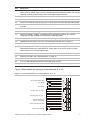
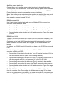
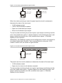
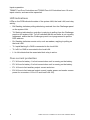
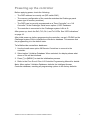
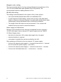
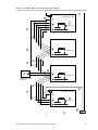
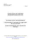
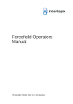
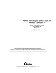
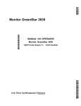
TS0867 Four-Door & TS0869 Four-Lift Controller Installation Manual P/N MAINST-867/869 • REV 5.0 • ISS 24SEP10 Copyright Trademarks and patents © 2010 UTC Fire & Security. All rights reserved. The Challenger name and logo are trademarks of UTC Fire & Security. Other trade names used in this document may be trademarks or registered trademarks of the manufacturers or vendors of the respective products. Manufacturer UTC Fire & Security Americas Corporation, Inc. 1275 Red Fox Rd., Arden Hills, MN 55112-6943, USA Authorized Australia and New Zealand manufacturing representative: UTC Fire & Security Australia Pty Ltd Unit 3, 310 Ferntree Gully Road, Notting Hill, VIC, 3168, Australia ACMA compliance Contact information N4131 Notice! This is a Class A product. In a domestic environment this product may cause radio interference in which case the user may be required to take adequate measures. For contact information, see www.utcfs.com.au. Content Important information ii Limitation of liability ii Agency compliance ii Product overview 1 Mechanical and environmental specifications 1 Product contents 1 Related documentation 2 Before you begin 3 Installing the Intelligent Access Controller 5 Installation guidelines 5 Installation procedures 6 DIP switch settings 6 Connections 7 Connecting expansion modules 15 LED indications 16 Over-current protection 16 Powering up the controller 17 Appendix A: Reference 19 Cabling requirements 19 System configurations 22 TS0867 Four-Door & TS0869 Four-Lift Controller Installation Manual i Important information Limitation of liability The customer is responsible for testing and determining the suitability of this product for specific applications. In no event is UTC Fire & Security responsible or liable for any damages incurred by the buyer or any third party arising from its use, or their inability to use the product. Disclaimer The information in this document is subject to change without notice. UTC Fire & Security Americas Corporation, Inc. (“UTC Fire & Security”) assumes no responsibility for inaccuracies or omissions and specifically disclaims any liabilities, losses, or risks, personal or otherwise, incurred as a consequence, directly or indirectly, of the use or application of any of the contents of this document. For the latest documentation, contact your local supplier or visit us online at www.utcfs.com.au. This publication may contain examples of screen captures and reports used in daily operations. Examples may include fictitious names of individuals and companies. Any similarity to names and addresses of actual businesses or persons is entirely coincidental. Intended use Use this product only for the purpose it was designed for; refer to the data sheet and user documentation for details. For the latest product information, contact your local supplier or visit us online at www.utcfs.com.au. Agency compliance This product conforms to the standards set by Standards Australia on behalf of the Australian Communications and Media Authority (ACMA). UTC Fire & Security recommend enclosure covers remain fitted to maintain C-Tick compliance. Notice! This is a Class A product. In a domestic environment this product may cause radio interference in which case the user may be required to take adequate measures. ii TS0867 Four-Door & TS0869 Four-Lift Controller Installation Manual Product overview This manual applies to TS0867 Four-Door Controller, and TS0869 Four-Lift Controller. These devices are also known as Intelligent Access Controllers, controllers, or DGPs. Up to 12 Intelligent Access Controllers can be connected to a Challenger panel’s RS-485 system LAN. Intelligent Access Controllers also have a local LAN to connect readers (for doors or lifts). TS0869 Four-Lift Controllers can have up to 15 DGPs on its local LAN, with each of the 15 DGPs providing up to 16 inputs (typically for floor-buttons). Intelligent Access Controllers provide enhanced access control functionality to the Challenger system. This manual describes: • How to install the Intelligent Access Controller • How to connect other equipment to the Intelligent Access Controller • Programming required for basic system setup This manual is intended for use only by trained Challenger installation and configuration technicians. Mechanical and environmental specifications Enclosure dimensions (W x H x D) 385 x 585 x 77 mm Storage temperature -20 to +80°C Operating environment Temperature Relative humidity 0 to 50°C 0 to 95% noncondensing Product contents Inspect the package and contents for visible damage. If any components are damaged or missing, do not use the unit; contact the supplier immediately. If you need to return the unit, you must ship it in the original box. Table 1: TS0867 or TS0869 shipping list Quantity Item 1 Metal enclosure (with four spring standoffs fitted) 1 TS0867 or TS0869 board 1 Installation Manual 1 Mains transformer, 5A, with mains power cord 1 Front tamper switch 1 Rear tamper switch 2 Ring terminal 1 M4 x 12 Allen head cap screw TS0867 Four-Door & TS0869 Four-Lift Controller Installation Manual 1 Quantity Item 2 M3 x 10 pan head screws 6 M3 x 8 pan head screws 25 3-way plug-on screw terminal connectors 13 2-way plug-on screw terminal connectors 2 Red battery lead with QC terminal 2 Black battery lead with QC terminal 4 Link jumpers 1 1K 1/4 watt resistor 40 10K 1/4 watt resistors Related documentation The Four-Door & Four Lift Controller Programming Manual provides detailed information about configuring and programming Four-Door and Four-Lift Controller models TS0866, TS0867, and TS0869. The Challenger V8 & V9 Installation and Quick Programming Manual provides detailed information about configuring a Challenger system. Details provided about a Challenger panel’s system LAN apply also to an Intelligent Access Controller’s local LAN. The Challenger V8 & V9 Programming Manual provides detailed information about Challenger system configuration and programming. The Challenger system is modular. Refer also to the documentation that is shipped with each module that you intend to use. 2 TS0867 Four-Door & TS0869 Four-Lift Controller Installation Manual Before you begin When installing an Intelligent Access Controller, or any other parts of the system, you need to be aware of requirements for cabling and earthing, and plan accordingly. Refer to “Cabling requirements” on page 19. Notice! A qualified service person, complying with all applicable codes, should perform all required hardware installation. Disclaimer: This manual contains recommendations based on Australia and New Zealand codes. It is not an authoritative reference regarding codes and has not been reviewed by the responsible authorities. The codes may change and may not be reflected in this document. TS0867 Four-Door & TS0869 Four-Lift Controller Installation Manual 3 4 TS0867 Four-Door & TS0869 Four-Lift Controller Installation Manual Installing the Intelligent Access Controller See Figure 1 below for overall details of a TS0867 Four-Door Controller or a TS0869 Four-Lift Controller installed in a TS0329 Large Enclosure (supplied). ~ BATT 1 F1 ~ AC BATT 2 F2 EPROM EPROM F3 EPROM EXT F4 + – + – BATT BATT RAM FLASH AUX + + – – – S+ S– AUX. POWER FLASH + RS232 Rx1 Tx1 Tx0 SW1 BZ L1 L2 D1 D0 0V +5 +12 DOOR 3 ON TERM 1 2 3 4 5 6 7 8 L1 K2 L2 L3 +12V C NC NO 0V RELAY K4 L4 +12 0V D+ D– COMMS +12V C NC NO 0V RELAY K3 TERM 0 V D + D - T C +12V C NC NO 0V COMMS TAMPER RELAY RAM Rx0 K5 +12V C NC NO 0V RELAY J21 1 C 2 C 3 C 1 1 BZ L1 L2 D1 D0 0V +5 +12 DOOR 2 GND BZ L1 L2 D1 D0 0V +5 +12 DOOR 4 1 BZ L1 L2 D1 D0 0V +5 +12 DOOR 1 Figure 1: TS0867 or TS0869 board mounted in enclosure 4 C 5 C 6 C Space for 12 V 7 Ah battery (not included) 1. Enclosure mounting points 2. Board mounting points 7 C 8 C 9 C 10 C 11 C 12 C ALARM INPUTS 13 C 14 C 15 C 16 C Space for 12 V 7 Ah battery (not included) 1 3. Rear tamper switch 4. Front tamper switch Installation guidelines Intelligent Access Controllers are designed, assembled and tested to meet the requirements related to safety, emission and immunity with respect to environmental electrical and electromagnetic interference, as of current relevant standards. In addition to the general installation guidelines, installers must adhere to any country dependent requirements of local applicable standards. Only a qualified electrician or other suitably trained and qualified person should attempt to wire this system to the mains. TS0867 Four-Door & TS0869 Four-Lift Controller Installation Manual 5 • Mount the unit using screws or bolts through the four mounting holes in the base. Ensure that the unit is mounted on a flat, solid, vertical surface so that the base will not flex or warp when the mounting screws or bolts are tightened. • Allow 50 mm clearance between the equipment enclosures mounted side by side, and 25 mm between the enclosure and any side wall or ceiling. • Each Challenger system device that has an earth terminal must be earthed by connecting it to a Communications Earth Terminal (CET). See “System earthing” on page 19 for details. • The Intelligent Access Controller has an internal transformer that is powered from 240 V mains (cable supplied). A power outlet (GPO) must be in proximity to the panel. Only qualified Electricians should provide a GPO. • If the upper and/or lower cabinet entry cable holes are used to route wiring into the control panel, always use a proper pipe fitting system by means of an appropriate conduit and junction box. For this purpose, use only materials of suitable flammability class. • Avoid loops of wire inside the enclosure, and route cables so that they do not lie on top or underneath the printed circuit board. The use of cable ties is recommended and improves neatness of the wiring within the box. • The batteries used with this unit must be made of materials of suitable flammability class (HB or better). • Only use units in a clean environment and not in humid air. Installation procedures To mount the enclosure: 1. Fix the enclosure to the wall via the enclosure’s four mounting holes (1) in Figure 1 on page 5. Make sure the enclosure is level, and the rear tamper switch (3) location isn’t sitting over a line of mortar if you’re installing the enclosure on a brick wall. To set the LAN address: Configure the DGP address in the range 1 to 12 using DIP switch SW1. Refer to “DIP switch settings” below. DIP switch settings Intelligent Access Controllers must have a DGP address in the range 1 to 12 for use on the Challenger system LAN. Use the eight-segment DIP switch SW1 to set the address (switches 5 to 8 are not used). Set all switches to OFF to disable the controller. 6 TS0867 Four-Door & TS0869 Four-Lift Controller Installation Manual Figure 2: Address DIP switch ON 1 2 3 4 5 6 7 8 SW1 Table 2: DIP switch settings Address S1-1 S1-2 S1-3 S1-4 01 I O O O 02 O I O O 03 I I O O 04 O O I O 05 I O I O 06 O I I O 07 I I I O 08 O O O I 09 I O O I 10 O I O I 11 I I O I 12 O O I I Legend: I = ON, O = OFF Connections See Figure 3 on page 8 for the locations of connectors and other items. See “Cabling requirements” on page 19 for recommendations for the application and wiring of Challenger equipment. TS0867 Four-Door & TS0869 Four-Lift Controller Installation Manual 7 F1 ~ AC F2 22 RAM FLASH EPROM EPROM F3 EPROM EXT F4 + – + – BATT BATT 26 AUX + RAM Rx0 RS232 Rx1 Tx1 Tx0 SW1 24 BZ L1 L2 D1 D0 0V +5 +12 DOOR 3 1 2 3 4 5 6 7 8 ON TERM L1 K2 L2 L3 +12V C NC NO 0V RELAY K4 L4 K5 +12V C NC NO 0V RELAY +12 0V D+ D– COMMS +12V C NC NO 0V RELAY K3 TERM + – – – S+ S– 0 V D + D - T C +12V C NC NO 0V AUX. POWER COMMS TAMPER RELAY FLASH + 23 BZ L1 L2 D1 D0 0V +5 +12 DOOR 2 ~ BATT 1 BATT 2 BZ L1 L2 D1 D0 0V +5 +12 DOOR 4 GND BZ L1 L2 D1 D0 0V +5 +12 DOOR 1 Figure 3: TS0867 or TS0869 board details 25 21 J21 1 C 2 C 3 C 4 C 5 C 6 C 7 C 8 C 9 C 10 C 11 C 12 C ALARM INPUTS 13 C 14 C 15 C 16 C Figure 3 legend Item Description 1. Connect the board’s earth terminal (or lug) via minimum 2.5mm² GNYE earth cable (not exceeding 1 Ω) to a Communications Earth Terminal (CET). See “System earthing” on page 19 for details. 2. The board’s ground link must remain fitted. 3. The AC terminals are connected to the transformer (supplied) at the factory (for models shipped with enclosure). 4. Connect the J1 connector’s earth terminal to the system LAN’s RS-485 data cable shield. See Figure 10 on page 21. See also “RS-485 LAN cabling” on page 20. 5. Connect the + and – terminals to a 12 V sealed lead acid battery (7.0 Ah maximum), not supplied. 6. Optionally, connect the second set of + and – terminals to a second 12 V sealed lead acid battery (7.0 Ah maximum), not supplied. 7. Connect the + and – auxiliary power output terminals to devices that require 12 Volt DC power, such as detectors. See “Auxiliary power terminals” on page 10. 8. Connect the S+ and S– terminals to an 8 siren speaker. Alternatively, connect a 1k Ω resistor across S+ and S– terminals if a siren is not connected. If a siren is used, consider the current draw as part of the auxiliary power output. See “Auxiliary power terminals” on page 10. 9. 8 Connect the 0V, D+ and D– terminals to the system LAN. TS0867 Four-Door & TS0869 Four-Lift Controller Installation Manual Item Description 10. Connect the T and C terminals to the front and rear tamper switches (supplied) in series. Short circuit for sealed, open circuit for unsealed. Must be sealed if not used. Can only be used with normally closed contacts such as the panel tamper switches. 11. J4 to J7: relay connections for four doors or lifts. 12. Zone input terminals. 13. Connect the earth terminal (or lug) near J14 to the local LAN’s RS-485 data cable shield. 14. J21: 10-way cable socket for TS0840, TS0841, or TS0842 relay or output expansion modules. 15. J22: Connect the +12, 0V, D+ and D– terminals to the local LAN’s RS-485 data cable. 16. J13 to J16: Four sets of Wiegand reader connections. 17. Socket for TS0882, TS0883, or TS0884 memory expansion modules. The memory configuration of the controller must match the Challenger panel. 18. Address selection DIP switch. See “DIP switch settings” on page 6. 19. TERM link for the system LAN. See “Terminating the RS-485 LAN” on page 11. 20. TERM link for the local LAN. See “Terminating the RS-485 LAN” on page 11. 21. K2 to K5 links. Lock Fault Monitoring option. These links must only be fitted on a lock output that is wired in the configuration for "Power Off to Lock" that is, power to unlock. This function is not currently implemented. 22. RAM, FLASH, EPROM links. Do not fit these links unless instructed to do so. 23. Rx0 and Tx0 LEDs. See “LED indications” on page 16. 24. Rx1 and Tx1 LEDs. See “LED indications” on page 16. 25. L1 to L4 LEDs indicate that the associated lock relay is active. 26. F1, F2, F3, F4 over-current protection. See “Over-current protection” on page 16. Figure 4 below details the wiring for terminal blocks J1 to J3. Figure 4: Connection details for terminal blocks J1 to J3 J1 AC 18 V AC power from mains transformer RS-485 data cable shield 12 V battery BATT BATT 12 V battery J2 Auxiliary power 12 VDC + Panel tamper switches TS0867 Four-Door & TS0869 Four-Lift Controller Installation Manual J3 System RS-485 data cable S+ S 0V D+ D T C COMMS TMPR 8 Ω siren speaker or 1KΩ 1/4 watt resistor AUX. POWER Auxiliary power 12 VDC – 9 Auxiliary power terminals Connect the + and – auxiliary power output terminals to devices that require 12 VDC power, such as detectors. Three sets of auxiliary power output terminals are provided: if you need more than three connections you can use a TS0844 Power Distribution Board to increase the number of terminals. Note: The auxiliary power output and siren speaker are supplied from one circuit. The maximum current draw for all auxiliary devices, local LAN (J22), and the siren speaker, must not exceed 700 mA. RS-485 system LAN Use 2-pair twisted shielded data cable such as Belden 8723 to connect the controller to the Challenger panel. • Connect the 0V terminal to the black wire. • Connect the D+ terminal to the white wire. The D+ terminal is data positive. • Connect the D– terminal to the green wire. The D– terminal is data negative. • Connect the data cable shield to the LAN earth connection (Figure 3 on page 8, item 4). RS-485 local LAN TS0867 Four-Door Controllers and TS0869 Four-Lift Controllers can have up to 16 RAS devices such as keypads, card readers, arming stations, or Smart Door Controllers on the local LAN. Sixteen devices might be required for four doors where each door has an in reader, an in keypad, an out reader, and an out keypad. In addition, the TS0869 Four-Lift Controller can have up to 15 DGPs on the local LAN. Use 2-pair twisted shielded data cable such as Belden 8723 to connect the controller to RASs and DGPs. • Connect the +12 terminal to the red wire. The +12 terminal provides +12 V to LAN devices such as RASs (within 100 m cabling distance). • Connect the 0V terminal to the black wire. The 0V terminal provides -ve DC to LAN devices such as RASs, and common 0 V for the RS-485 LAN. • Connect the D+ terminal to the white wire. The D+ terminal is data positive. • Connect the D– terminal to the green wire. The D– terminal is data negative. • Connect the data cable shield to the LAN earth connection (Figure 3 on page 8, item 13). The RS-485 LAN may be used to power devices up to 100 m cabling distance from the controller. See “Power supply to LAN devices” on page 20 for details. One set of LAN terminals is provided, if you need more than one connection you can use a TS0844 Power Distribution Board to increase the number of terminals. 10 TS0867 Four-Door & TS0869 Four-Lift Controller Installation Manual Figure 5: Connecting a Smart Card Reader to the local LAN DD+ 0V +12 Green White Black Red Connect shield to earth terminal Terminating the RS-485 LAN All Challenger LAN devices (including the panel) use a 470 Ω LAN termination resistor where required. LAN termination resistors are used to set the impedance of the LAN to around 220 Ω in order to minimise noise. The termination resistor may be external or onboard (devices with an onboard resistor use a link to set the LAN termination to ON). A Challenger LAN should have only two devices with the LAN termination set to ON (or the LAN termination resistor fitted): • In a straight LAN configuration ((Figure 10 on page 21) the TERM links are ON at the Challenger panel and the most distant device. • In a star LAN configuration (Figure 11 on page 23) the TERM links are ON at the two devices that are the furthest apart (and OFF at the Challenger panel). In a completely-connected (but powered down) system, you can check for correct LAN termination by measuring the resistance across the D+ and D– terminals: • ~0 Ω indicates a short circuit in the cabling • ~160 Ω or less indicates that three or more devices are terminated • ~220 Ω is good (two devices are terminated) • ~470 Ω or more indicates that less than two devices are terminated Door lock relay wiring Figure 6 on page 12 details the wiring for terminal blocks J4 to J7. TS0867 Four-Door & TS0869 Four-Lift Controller Installation Manual 11 Figure 6: Door lock wiring options (relay shown deenergised) Door lock (power to lock) Lock powered by controller 250 mA maximum per lock External 12 V power supply Door lock (power to lock) Lock powered externally Door lock (power to unlock) Lock powered by controller 250 mA maximum per lock External 12 V power supply Door lock (power to unlock) Lock powered externally Note: Use a suppression diode such as 1N4004 in door lock circuits. Zone inputs Zone inputs are also known as alarm inputs. A Challenger system can receive alarm signals from up to 256 zone inputs, including the Challenger panel’s 16 onboard inputs. Each pair of zone input terminals may be connected to an alarm system device, such as a detector or reed switch. Additional zone inputs, numbered in the range 17 to 256, are provided via Data Gathering Panels (DGPs), Wireless Data Gathering Panels (WDGPs) and Intelligent Access Controllers on the system LAN. By default, the Challenger system can monitor zone inputs for four states (sealed, unsealed, open circuit, and short circuit). This is accomplished by using two 10 kΩ end-of-line (EOL) resistors in each zone input circuit, as shown in Figure 7 on page 13. Install EOL resistors in zone input circuits at the end of the circuit. If an alarm device is connected, place the EOL resistors at the device’s connections. If a zone input is not used, you don’t need to connect an EOL resistor if you program the corresponding input number as type 10 (spare). Tip: Use sleeves on the resistor leads to prevent accidental shorting. 12 TS0867 Four-Door & TS0869 Four-Lift Controller Installation Manual Figure 7: Four-state monitored zone input circuits 1 C 2 C 3 C 4 C 5 C 6 C 7 C 8 C 9 C 10 C 11 C 12 C Normally open tamper contact Normally closed tamper contact 10K 10K 10K 13 C 14 C 15 C 16 C 10K Normally open alarm contact Normally closed alarm contact When four-state monitoring is used, the panel uses the circuit’s resistance to determine the state of the zone input: • 10 kΩ indicates sealed • 5 kΩ or 20 kΩ indicates unsealed • Open circuit indicates input tamper • Short circuit indicates input tamper To use four-state monitoring for all zone inputs, input tamper monitoring must be set to Yes (Install menu option 7, System Options) for the Challenger panel, and tamper monitoring must be set to Yes (controller menu option 1, Controller Options) for the controller. Alternatively, the Challenger system can be configured to monitor zone inputs for two states (sealed and unsealed). This is accomplished by using one 10 kΩ resistor in each circuit, as shown in Figure 8 below. Figure 8: Two-state monitored zone input circuits 1 C 2 C 3 C 10K 4 C 5 C 6 C 7 C 8 C 9 C 10 C 11 C 12 C Normally closed tamper contact Normally closed alarm contact 13 C 14 C 15 C 16 C Normally open tamper contact 10K Normally open alarm contact The panel uses the circuit’s resistance to determine the state of the zone input: • 10 kΩ indicates sealed • Open circuit or short circuit indicates unsealed To use two-state monitoring for all zone inputs, input tamper monitoring must be set to No (Install menu option 7, System Options) for the Challenger panel, and tamper monitoring must be set to No (controller menu option 1, Controller Options) for the controller. TS0867 Four-Door & TS0869 Four-Lift Controller Installation Manual 13 Note: Two-state monitoring is not compatible with input types 33 or 40. See the Challenger V8 & V9 Programming Manual for details. Default zone inputs and relays Door contacts and egress buttons associated with each door are wired to the Four-Door Controller’s zone inputs. Spare zone inputs for Four-Door Controllers and Four-Lift Controllers are provided for alarm devices such as PIRs. DOTL inputs must not have any wiring connected to them. Floor monitoring and security override inputs are wired to the Four-Lift Controller’s zone inputs or to the zone inputs of a DGP on the Four-Lift Controller’s local LAN. Table 3: Four-Door Controller zone input and relay defaults First door Second door Third door Fourth door Door contact 1 4 7 10 Spare input 2 5 8 11 Egress input 3 6 9 12 DOTL input 16 15 14 13 Door relay First Second Third Fourth Table 4: Four-Lift Controller floor, zone input and relay defaults First lift Second lift Third lift Fourth lift Starting floor 1 1 1 1 Last floor 64 64 64 64 Starting relay 1 65 129 193 Starting input 1 65 129 193 The zone input numbers in this section refer to the physical input numbers on the controller’s PCB. Refer to the Four-Door & Four Lift Controller Programming Manual for the system zone input numbers relating to these functions. Wiegand reader connections The TS0867 Four-Door Controller and the TS0869 Four-Lift Controller can have four Wiegand devices, such as readers, connected to terminal blocks J13 to J16. Wiegand readers can be used as an alternative to (or in addition to) local LAN devices. Figure 9 on page 15 details the typical Wiegand reader wiring used with a TS0870 Smart Card Reader. 14 TS0867 Four-Door & TS0869 Four-Lift Controller Installation Manual Figure 9: Connecting a Smart Card Reader as a Wiegand device +12 Red +5 0V D0 D1 L2 L1 BZ Black Green White Yellow Brown Blue Violet Connect shield to earth terminal In Figure 9 above, the violet wire (open collector output) can be connected to a zone input via a 10K resistor to operate as a tamper input (refer to the reader’s installation guide for details). Note: Figure 9 above shows the cable provided with TS0870 Smart Card Readers. Other Wiegand readers may be connected using 6-core shielded data cable (Belden 9536 or equivalent). Connecting expansion modules Relay and output expansion The Intelligent Access Controller has four onboard relays that are assigned the first four relay numbers for the DGP address. For DGP 1 these would be relays 17, 18, 19, and 20. If relay expansion cards are used, additional relays are numbered according to their physical address, starting at 5. A DGP macro logic program would be used to map the Challenger system’s DGP relay number (e.g. 21) to the Intelligent Access Controller’s physical relay number (e.g. 5). There are 48 DGP macro logic programs available. One TS0840 Four-Way Relay Expansion Board may be connected to J21 to add four relays. Alternatively, TS0841 Eight-Way Clocked Relay Expansion Boards or TS0842 16-Way Clocked Open Collector Expansion Boards may be connected to J21 individually or daisy-chained to add eight relays per card (for TS0841) or 16 open collector outputs per card (for TS0842). Note: If TS0841 and/or TS0842 boards are used, then a Relay Controllers value must be programmed in Controller Options, where 1 represents each eight relays or open collector outputs. Refer to the Four-Door & Four Lift Controller Programming Manual for details. TS0867 Four-Door & TS0869 Four-Lift Controller Installation Manual 15 Input expansion TS0867 Four-Door Controllers and TS0869 Four-Lift Controllers have 16 zone inputs circuits, and cannot be expanded. LED indications LEDs on the PCB indicate the state of the system LAN, the local LAN, and relay activity. • Rx0 flashing indicates polling data being received from the Challenger panel on the system LAN. • Tx0 flashing indicates the controller is replying to polling from the Challenger panel on the system LAN. Tx0 off indicates that the controller is not correctly addressed, and/or that the Challenger panel is not programmed to poll the DGP address. • Rx1 flashing indicates remote units, such as readers, replying to polling on the local LAN. • Tx1 rapid flashing if a RAS is connected to the local LAN. • Tx1 off if no RAS is connected to the local LAN. • L1 to L4 indicate that the associated lock relay is active. Over-current protection • F1. 3A fuse for battery 1 to limit current when unit is running on the battery. • F2. 3A fuse for battery 2 to limit current when unit is running on the battery. • F3. 1A fuse to limit auxiliary output current and siren. • F4. 2A fuse to limit external output current (reader power and reader comms power for connectors J13 to J16 and local LAN J22). 16 TS0867 Four-Door & TS0869 Four-Lift Controller Installation Manual Powering up the controller Before applying power, check the following: • The DGP address is correctly set (DIP switch SW1). • The memory configuration of the controller matches the Challenger panel (same type of memory modules). • The DGP type is correctly programmed as a “Door Controller” or a “Lift Controller” in the Challenger Install menu option 4, DGP Database. • The controller is connected to the Challenger system LAN at J3. After power-up, check the Rx0, Tx0, Rx1, and Tx1 LEDs. See “LED indications” on page 16. After initial power-up, before programming the controller, use an LCD RAS on the Challenger system LAN to initialise the controller’s database. This ensures that the programming is in the default state. To initialise the controller’s database: 1. Use the Install menu option 28 Remote Controllers to connect to the controller. 2. Select option 3 Initialise Database. When selected, the display shows what doors or lifts will be initialised. 3. Press [*] or [MENU*] to start the initialisation process. 4. Refer to the Four-Door & Four Lift Controller Programming Manual for details. Note: Menu option 3 Initialise Database, defaults the Intelligent Access Controller database, resetting all programming options to the factory defaults. TS0867 Four-Door & TS0869 Four-Lift Controller Installation Manual 17 18 TS0867 Four-Door & TS0869 Four-Lift Controller Installation Manual Appendix A: Reference Cabling requirements This section contains recommendations for installers and electricians for the application and wiring of Challenger equipment with respect to: • System earthing • Wiegand reader cabling • RS-485 data cable (LAN) cabling • Power supply from LAN or from external 12 V supply System earthing The following recommendations are based upon Australian wiring regulations ACMA AS/ACIF S009 Section 5 and AS/NZS 3000:2000 Section 5. • Each device’s GND link must remain fitted (if applicable). • Challenger system equipment with earth terminals must be earthed via minimum 2.5 mm² GNYE earth cable (not exceeding 1 Ω) to a Communications Earth Terminal (CET). Daisy chain connections are not permitted. • The CET must be labelled “Communications Earth Terminal” and installed adjacent to the electrical switchboard. • Each CET must be connected via minimum 6 mm² GNYE earth cable (not exceeding 0.5 Ω) to the electrical switchboard. (Only licensed electrical workers are permitted to add/remove/ join/repair connections within the electrical switchboard.) • Install LAN isolation devices between multiple buildings and maintain independent earthing systems. For example, use TS0893, TS0894, or TS0896 Isolation Interface modules to provide electrical isolation and/or to extend distance. • Do not install multiple main earth electrodes (stakes) in the same building or electrical installation. Earthing of one cabinet containing several devices. All devices designed for the system have earth connections via metal studs to the metal housing. Take care that these metal studs have a good connection to bare metal (no paint). Earthing of panels in a single building. In a single building several cabinets or devices are earthed. A licensed electrical contractor must check the integrity of the building main earth. Earthing of panels in more than one building. If the wiring extends to separate buildings, use more than one common earth system. Install LAN isolation devices, such as TS0893, to isolate the system LAN between buildings to protect the system against differences in earth potential. See Figure 12 on page 23. TS0867 Four-Door & TS0869 Four-Lift Controller Installation Manual 19 Wiegand reader cabling The recommended cable for the four onboard Wiegand terminal blocks J13 to J16 is 6-core shielded data cable (Belden 9536 or equivalent). The recommended maximum cabling distance is 50 m. RS-485 LAN cabling The cabling recommendations for the system LAN or local LAN are: • Use 2-pair twisted shielded data cable such as Belden 8723. • In each segment of LAN cabling, connect one end only of the data cable shield to a device’s LAN earth terminal. Join data cable shields where cable extends past a device that doesn’t have a LAN earth connection. • The length of the LAN cable run must not exceed 1.5 km, unless LAN isolation devices are used to extend the distance. Power supply to LAN devices Devices on the controller’s local LAN may be supplied from the controller’s 12 VDC LAN output. Use an external 12 V power supply (such as TS0073 2 A Power Supply) when: • the device is more than 100 m (data cable length) from the panel • electrical isolation is required • more power is needed than can be provided by the LAN When powering a LAN device from an external 12 V power supply: • Connect the external power supply’s ‘+’ terminal to the device’s ‘+’ terminal. Do not connect the power supply + to the LAN +. • Connect the external power supply’s ‘–‘ terminal to the device ‘–’ terminal. • Connect the LAN cable black wire ‘–’ to the device ‘–’ terminal. 20 TS0867 Four-Door & TS0869 Four-Lift Controller Installation Manual Figure 10: RS-485 LAN and earth system block diagram 1 EARTH 6 Challenger panel (first device on LAN) 9 D+ D TERM link on 4 Plastic bodied RAS 5 D+ D TERM link off 4 Plastic bodied RAS 8 7 D+ D TERM link off External power supply (if needed) 1 EARTH 4 6 Data gathering panel (last device on LAN) 9 D+ D TERM link on 2 3 TS0867 Four-Door & TS0869 Four-Lift Controller Installation Manual CET 21 Figure 10 legend Item Description 1. Each device’s earth point must be connected via minimum 2.5 mm² GNYE earth cable (not exceeding 1 Ω) to a Communications Earth Terminal (CET). If the device has a GND link, it must remain fitted. 2. The CET must be labelled “CET” and installed adjacent to the electrical switchboard. 3. Minimum 6 mm² GNYE earth cable (not exceeding 0.5 Ω) to building earth or electrical switchboard. 4. RS-485 LAN cable. GE recommends the use of 2-pair twisted shielded data cable such as Belden 8723 for optimal performance. 5. Join data cable shields where cable extends past a device that doesn’t have a LAN earth connection. 6. In each segment of LAN cabling, connect one end only of the data cable shield to a device’s LAN earth terminal. 7. External 12 VDC power supply (if needed). 8. Do not connect the + from the external 12 VDC power supply to the + of the LAN. 9. Terminate the control panel and the most distant device, or the devices at the ends of the two longest LAN cable runs, as applicable. System configurations A Challenger panel’s system LAN or an Intelligent Access Controller’s local LAN may be configured in a variety of ways: • Straight LAN, where the Challenger panel (or controller) is at one end of a LAN cable run • Star LAN, where multiple LAN cable runs are used in a branched configuration • Multi-building, where the LAN extends to more than one building Straight LAN In a straight configuration (Figure 10 on page 21), the panel or controller is at one end of the LAN cable run and all other devices are connected to the LAN cable. In a straight LAN configuration, the TERM links would be on for the panel (or controller) and for the last device on the system or local LAN. Star LAN In a star configuration, the LAN has at least two branches (Figure 11 on page 23) optionally connected via a TS0844 Power Distribution Board. In a star LAN configuration, the TERM links would be on for the two devices at the ends of the two longest cable runs. 22 TS0867 Four-Door & TS0869 Four-Lift Controller Installation Manual Figure 11: Star LAN configuration T=Off DGP TS0844 T=On T=On Challenger panel T=On (termination link fitted) T=Off (termination link not fitted) T=Off Multi-building or long-distance LAN cabling If the RS-485 LAN extends to more than one building, each building must have its own earth system. LAN isolation devices, such as TS0893, are used to isolate the system LAN between buildings to protect the system against differences in earth potential. Figure 12 below shows the use of two TS0893 Isolated RS-485 to RS-485 Interface modules to extend the RS-485 LAN across two electrical installations. Each TS0893 module has a pair of termination links, used to terminate (if applicable) the LAN segment on each side of the module’s isolation barrier. Figure 12: RS-485 LAN cabling between two buildings Building A Building B Challenger Panel DGP DGP T=On T=Off T=On T=Off TS0893 TS0893 T=On T=On T=On T=On CET CET T=On (termination link fitted) T=Off (termination link not fitted) TS0867 Four-Door & TS0869 Four-Lift Controller Installation Manual 23 Figure 12 legend Item Description 1. LAN segment 1 extends from the Challenger panel to one side of the TS0893 LAN Isolation Interface. Termination is ON at the panel and the panel’s side of the TS0893. Maximum cabling distance for segment 1 is 1500 metres. 2. LAN segment 2 extends from the TS0893 in building A to the TS0893 in building B. Termination is ON at both TS0893 modules. Maximum cabling distance for segment 2 is 1500 metres. 3. Earth point on device. 4. Each device’s earth point must be connected via minimum 2.5mm² GNYE earth cable (not exceeding 1 Ω) to a Communications Earth Terminal (CET). 5. Minimum 6mm² GNYE earth conductor not exceeding 0.5 Ω. See “System earthing” on page 19 for details. 6. Plastic-body LAN device. See Figure 10 on page 21 for details of joining the data cable shield to extend the LAN past such a device. 24 TS0867 Four-Door & TS0869 Four-Lift Controller Installation Manual