1
NetHub
Software Manual
Version 1.0
Last Revised October 21, 2011
All contents in this manual are copyrighted by JAVAD GNSS.
All rights reserved.The information contained herein may not be used, accessed, copied,
stored, displayed, sold, modified, published, or distributed, or otherwise reproduced without express written
consent from JAVAD GNSS
www.javad.com
TABLE OF CONTENTS
Preface . . . . . . . . . . . . . . . . . . . . . . . . . . . . . . . . . . . . . . . . . . . . . . . . . . . . . . . . . . . . . . 5
Terms and Conditions. . . . . . . . . . . . . . . . . . . . . . . . . . . . . . . . . . . . . . . . . . . . . . . . . . . . . . . . 5
About this Manual . . . . . . . . . . . . . . . . . . . . . . . . . . . . . . . . . . . . . . . . . . . . . . . . . . . . . . . . . . 7
Technical Assistance . . . . . . . . . . . . . . . . . . . . . . . . . . . . . . . . . . . . . . . . . . . . . . . . . . . . . . . . 7
Chapter 1. Getting Started . . . . . . . . . . . . . . . . . . . . . . . . . . . . . . . . . . . . . . . . . . . . . . . 9
1.1. Setting up NetHub . . . . . . . . . . . . . . . . . . . . . . . . . . . . . . . . . . . . . . . . . . . . . . . . . . . . . . 10
1.1.1. System requirements . . . . . . . . . . . . . . . . . . . . . . . . . . . . . . . . . . . . . . . . . . . . . . . 10
1.1.2. Installing NetHub . . . . . . . . . . . . . . . . . . . . . . . . . . . . . . . . . . . . . . . . . . . . . . . . . 10
1.1.3. Uninstalling NetHub . . . . . . . . . . . . . . . . . . . . . . . . . . . . . . . . . . . . . . . . . . . . . . . 11
1.2. Getting Connected . . . . . . . . . . . . . . . . . . . . . . . . . . . . . . . . . . . . . . . . . . . . . . . . . . . . . . 11
1.2.1. Starting NetHub. . . . . . . . . . . . . . . . . . . . . . . . . . . . . . . . . . . . . . . . . . . . . . . . . . . 11
1.2.2. Establishing connection. . . . . . . . . . . . . . . . . . . . . . . . . . . . . . . . . . . . . . . . . . . . . 12
1.2.3. TCP connection . . . . . . . . . . . . . . . . . . . . . . . . . . . . . . . . . . . . . . . . . . . . . . . . . . . 13
1.2.4. Serial connection . . . . . . . . . . . . . . . . . . . . . . . . . . . . . . . . . . . . . . . . . . . . . . . . . . 13
1.2.5. USB connection. . . . . . . . . . . . . . . . . . . . . . . . . . . . . . . . . . . . . . . . . . . . . . . . . . . 14
1.2.6. CAN connection . . . . . . . . . . . . . . . . . . . . . . . . . . . . . . . . . . . . . . . . . . . . . . . . . . 15
1.2.7. REMOTE Connection . . . . . . . . . . . . . . . . . . . . . . . . . . . . . . . . . . . . . . . . . . . . . . 15
1.2.8. Closing NetHub. . . . . . . . . . . . . . . . . . . . . . . . . . . . . . . . . . . . . . . . . . . . . . . . . . . 16
Chapter 2. Server Configuration . . . . . . . . . . . . . . . . . . . . . . . . . . . . . . . . . . . . . . . . . . 17
2.1. Hub Settings . . . . . . . . . . . . . . . . . . . . . . . . . . . . . . . . . . . . . . . . . . . . . . . . . . . . . . . . . . 17
2.2. Hub Connections . . . . . . . . . . . . . . . . . . . . . . . . . . . . . . . . . . . . . . . . . . . . . . . . . . . . . . . 18
2.3. NTRIP Settings . . . . . . . . . . . . . . . . . . . . . . . . . . . . . . . . . . . . . . . . . . . . . . . . . . . . . . . . 19
2.3.1. Setup Base . . . . . . . . . . . . . . . . . . . . . . . . . . . . . . . . . . . . . . . . . . . . . . . . . . . . . . . 19
2.4. Raw TCP accounts. . . . . . . . . . . . . . . . . . . . . . . . . . . . . . . . . . . . . . . . . . . . . . . . . . . . . . 20
2.4.1. Setup Rover . . . . . . . . . . . . . . . . . . . . . . . . . . . . . . . . . . . . . . . . . . . . . . . . . . . . . . 21
2.5. Task Templates . . . . . . . . . . . . . . . . . . . . . . . . . . . . . . . . . . . . . . . . . . . . . . . . . . . . . . . . 23
2.5.1. Save . . . . . . . . . . . . . . . . . . . . . . . . . . . . . . . . . . . . . . . . . . . . . . . . . . . . . . . . . . . . 24
2.5.2. Upload to FTP . . . . . . . . . . . . . . . . . . . . . . . . . . . . . . . . . . . . . . . . . . . . . . . . . . . . 24
2.5.3. Run Batch File. . . . . . . . . . . . . . . . . . . . . . . . . . . . . . . . . . . . . . . . . . . . . . . . . . . . 25
2.5.4. RINEX Settings. . . . . . . . . . . . . . . . . . . . . . . . . . . . . . . . . . . . . . . . . . . . . . . . . . . 27
2.6. FTP Accounts . . . . . . . . . . . . . . . . . . . . . . . . . . . . . . . . . . . . . . . . . . . . . . . . . . . . . . . . . 27
2.7. Email Notifications . . . . . . . . . . . . . . . . . . . . . . . . . . . . . . . . . . . . . . . . . . . . . . . . . . . . . 29
www.javad.com
3
2.8. Map . . . . . . . . . . . . . . . . . . . . . . . . . . . . . . . . . . . . . . . . . . . . . . . . . . . . . . . . . . . . . . . . . 30
2.9. Hub Logs . . . . . . . . . . . . . . . . . . . . . . . . . . . . . . . . . . . . . . . . . . . . . . . . . . . . . . . . . . . . 30
2.10. Action Logs . . . . . . . . . . . . . . . . . . . . . . . . . . . . . . . . . . . . . . . . . . . . . . . . . . . . . . . . . 31
Chapter 3. Operation with Receiver . . . . . . . . . . . . . . . . . . . . . . . . . . . . . . . . . . . . . . . 33
3.1. Working with the receiver . . . . . . . . . . . . . . . . . . . . . . . . . . . . . . . . . . . . . . . . . . . . . . .
3.1.1. Measurements tab . . . . . . . . . . . . . . . . . . . . . . . . . . . . . . . . . . . . . . . . . . . . . . . . .
3.1.2. Sky Plot tab. . . . . . . . . . . . . . . . . . . . . . . . . . . . . . . . . . . . . . . . . . . . . . . . . . . . . .
3.1.3. Orientation . . . . . . . . . . . . . . . . . . . . . . . . . . . . . . . . . . . . . . . . . . . . . . . . . . . . . .
3.1.4. Options . . . . . . . . . . . . . . . . . . . . . . . . . . . . . . . . . . . . . . . . . . . . . . . . . . . . . . . . .
3.1.5. Settings . . . . . . . . . . . . . . . . . . . . . . . . . . . . . . . . . . . . . . . . . . . . . . . . . . . . . . . . .
33
34
36
36
36
37
3.2. Working with Files . . . . . . . . . . . . . . . . . . . . . . . . . . . . . . . . . . . . . . . . . . . . . . . . . . . . . 38
3.3. Configuring the Receiver . . . . . . . . . . . . . . . . . . . . . . . . . . . . . . . . . . . . . . . . . . . . . . . .
3.3.1. General tab . . . . . . . . . . . . . . . . . . . . . . . . . . . . . . . . . . . . . . . . . . . . . . . . . . . . . .
3.3.2. TriPad . . . . . . . . . . . . . . . . . . . . . . . . . . . . . . . . . . . . . . . . . . . . . . . . . . . . . . . . . .
3.3.3. Positioning . . . . . . . . . . . . . . . . . . . . . . . . . . . . . . . . . . . . . . . . . . . . . . . . . . . . . .
3.3.4. Base . . . . . . . . . . . . . . . . . . . . . . . . . . . . . . . . . . . . . . . . . . . . . . . . . . . . . . . . . . .
3.3.5. Rover . . . . . . . . . . . . . . . . . . . . . . . . . . . . . . . . . . . . . . . . . . . . . . . . . . . . . . . . . .
3.3.6. Ports . . . . . . . . . . . . . . . . . . . . . . . . . . . . . . . . . . . . . . . . . . . . . . . . . . . . . . . . . . .
3.3.7. Networking Tab . . . . . . . . . . . . . . . . . . . . . . . . . . . . . . . . . . . . . . . . . . . . . . . . . .
3.3.8. Event Tab . . . . . . . . . . . . . . . . . . . . . . . . . . . . . . . . . . . . . . . . . . . . . . . . . . . . . . .
3.3.9. Advanced . . . . . . . . . . . . . . . . . . . . . . . . . . . . . . . . . . . . . . . . . . . . . . . . . . . . . . .
40
41
43
45
51
54
57
61
68
69
3.4. GREIS Commands . . . . . . . . . . . . . . . . . . . . . . . . . . . . . . . . . . . . . . . . . . . . . . . . . . . . . 77
3.4.1. Load Script Button . . . . . . . . . . . . . . . . . . . . . . . . . . . . . . . . . . . . . . . . . . . . . . . . 79
4
www.javad.com
PREFACE
The materials available in this User Manual (the “Manual”) have been prepared by JAVAD GNSS for
owners of JAVAD GNSS products. It is designed to assist owners with the operating of the NetHub
Software and its use is subject to these terms and conditions (the “Terms and Conditions”).
Note: Please read these Terms and Conditions carefully.
Terms and Conditions
USE – JAVAD GNSS products are designed to be used by a professional. The user is expected to have a
good knowledge and understanding of the user and safety instructions before operating, inspecting or
adjusting. Always wear the required protectors (safety shoes, helmet, etc.) when operating the receiver.
COPYRIGHT – All information contained in this Manual is the intellectual property of, and copyrighted
material of JAVAD GNSS. All rights are reserved. You may not use, access, copy, store, display, create
derivative works of, sell, modify, publish, distribute, or allow any third party access to, any graphics,
content, information or data in this Manual without JAVAD GNSS’ express written consent and may only
use such information for the operation of your software. The information and data in this Manual are a
valuable asset of JAVAD GNSS and are developed by the expenditure of considerable work, time and
money, and are the result of original selection, coordination and arrangement by JAVAD GNSS.
TRADEMARKS – NetHub ™, JAVAD GNSS ® are trademarks or registered trademarks of JAVAD
GNSS. Windows® is a registered trademark of Microsoft Corporation, Bluetooth® word mark is owned
by the Bluetooth SIG, Inc. Product and company names mentioned herein may be trademarks of their
respective owners.
DISCLAIMER OF WARRANTY – EXCEPT FOR ANY WARRANTIES IN THIS GUIDE OR A
WARRANTY CARD ACCOMPANYING THE PRODUCT, THIS GUIDE AND SOFTWARE ARE
PROVIDED “AS-IS.” THERE ARE NO OTHER WARRANTIES. JAVAD GNSS DISCLAIMS ANY
IMPLIED WARRANTY OF MERCHANTABILITY OR FITNESS FOR ANY PARTICULAR USE OR
PURPOSE. JAVAD GNSS AND ITS DISTRIBUTORS SHALL NOT BE LIABLE FOR TECHNICAL
OR EDITORIAL ERRORS OR OMISSIONS CONTAINED HEREIN; NOR FOR INCIDENTAL OR
CONSEQUENTIAL DAMAGES RESULTING FROM THE FURNISHING, PERFORMANCE OR
USE OF THIS MATERIAL. SUCH DISCLAIMED DAMAGES INCLUDE BUT ARE NOT LIMITED
TO LOSS OF TIME, LOSS OR DESTRUCTION OF DATA, LOSS OF PROFIT, SAVINGS OR
REVENUE, OR LOSS OF THE PRODUCT'S USE. IN ADDITION, JAVAD GNSS IS NOT
RESPONSIBLE OR LIABLE FOR DAMAGES OR COSTS INCURRED IN CONNECTION WITH
O B TA I N I N G S U B S T I T U T E P RO D U C T S O R S O F T WA R E , C L A I M S B Y OT H E R S ,
INCONVENIENCE, OR ANY OTHER COSTS. IN ANY EVENT, JAVAD GNSS SHALL HAVE NO
www.javad.com
5
Preface
Terms and Conditions
LIABILITY FOR DAMAGES OR OTHERWISE TO YOU OR ANY OTHER PERSON OR ENTITY IN
EXCESS OF THE PURCHASE PRICE FOR THE NetHub SOFTWARE.
LICENSE AGREEMENT – Use of any computer programs or software supplied by JAVAD GNSS or
downloaded from a JAVAD GNSS website (the “Software”) in connection with the JAVAD GNSS
receivers constitutes acceptance of these Terms and Conditions in this Manual and an agreement to abide
by these Terms and Conditions. The user is granted a personal, non-exclusive, non-transferable license to
use such Software under the terms stated herein and in any case only with a single computer. You may not
assign or transfer the Software or this license without the express written consent of JAVAD GNSS. This
license is effective until terminated. You may terminate the license at any time by destroying the Software
and Manual. JAVAD GNSS may terminate the license if you fail to comply with any of the Terms or
Conditions. You agree to destroy the Software and guide upon termination of your use of software. All
ownership, copyright and other intellectual property rights in and to the Software belong to JAVAD
GNSS. If these license terms are not acceptable, return any unused software and guide.
CONFIDENTIALITY – This Manual, its contents and the Software (collectively, the “Confidential
Information”) are the confidential and proprietary information of JAVAD GNSS. You agree to treat
JAVAD GNSS' Confidential Information with a degree of care no less stringent that the degree of care you
would use in safeguarding your own most valuable trade secrets. Nothing in this paragraph shall restrict
you from disclosing Confidential Information to your employees as may be necessary or appropriate to
operate NetHub Software. Such employees must also keep the Confidentiality Information confidential.
In the event you become legally compelled to disclose any of the Confidential Information, you shall give
JAVAD GNSS immediate notice so that it may seek a protective order or other appropriate remedy.
WEBSITE; OTHER STATEMENTS – No statement contained at the JAVAD GNSS website (or any other
website) or in any other advertisements or JAVAD GNSS literature or made by an employee or
independent contractor of JAVAD GNSS modifies these Terms and Conditions (including the Software
license, warranty and limitation of liability).
MISCELLANEOUS – The above Terms and Conditions may be amended, modified, superseded, or
canceled, at any time by JAVAD GNSS. The above Terms and Conditions will be governed by, and
construed in accordance with, the laws of the State of California, without reference to conflict of laws.
6
www.javad.com
Preface
About this Manual
Screen Captures
About this Manual
This Manual is designed to help you get familiar with the NetHub User Interface and introduce you to the
NetHub main features.
This Manual uses the following text conventions:
Example
Main
Description.
Titles of dialog windows/boxes, names of menu options.
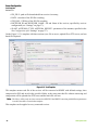
Screen Captures
This Manual includes sample screen captures. Your actual screen can look slightly different from the
sample screen due to the receiver you have connected, operating system used and settings you have
specified. This is normal and not a cause for concern.
Technical Assistance
If you have a problem and cannot find the information you need in the product documentation, contact
your local dealer. Alternatively, request technical support using the JAVAD GNSS World Wide Web site
at: www.javad.com.
To contact JAVAD GNSS Customer Support use the QUESTIONS button available on the
www.javad.com.
www.javad.com
7
Notes:
Chapter 1
GETTING STARTED
NetHub is a Windows application for controlling navigation receivers developed and manufactured by
JAVAD GNSS. Before you start using NetHub, you should become familiar with its functions and learn
how to install, launch, exit, and uninstall the program.
NetHub software provides the following functionality:
• Tasks Scheduling:
• Save file(s) to hard drive
• Upload file(s) to FTP server
• BAT scripts support
• Data Processing options:
• ZIP compression
• Subfolders by dates, receiver name, ID, etc.
• Automatic RINEX 2.11 converting;
• Directly connect to the receiver(s), using one of the following interfaces: serial, USB, TCP/IP
(through the Ethernet ports or WiFi adapter), Secure TCP/IP (TSL/SSL), Bluetooth, CAN (Kvaser
CAN Interface).
• Displaying of the total number and the status of all visible and tracked satellites.
• Displaying the receiver’s current position and time in real time.
• Real time satellites mapping.
• Setup of various parameters of receiver.
• Clear NVRAM, receiver reset, return to the initial parameter values.
• Start and stop file recording, deleting files, downloading files using file manager.
• Display of the current receiver options and loading of Option Authorization Files into the receiver.
• Manual mode terminal allows sending commands with prompt tip and view receiver response.
This terminal supports a TCL script language to automate the “common” receiver control tasks.
• Connecting to multiple receivers.
• Support for multiple connections to the receiver for optimized simultaneous work
• Firmware update (available starting with firmware version 3.2.1).
www.javad.com
9
Getting Started
Setting up NetHub
System requirements
1.1. Setting up NetHub
1.1.1. System requirements
Check that you have the following required (or recommended) items before installing and using NetHub.
•
•
•
•
PC-compatible with Intel® Pentium® Class 1.8 GHz or faster.
10 GB free disk space (determined by the total size of the memory of all connected receivers).
1 GB RAM or more (2 GB recommended).
32-bit or 64-bit operating system such as Windows XP, Windows Server 2003, Windows Server
2008, Windows Vista, Windows 7.
• Color monitor at 800x600 screen resolution.
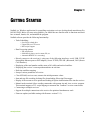
1.1.2. Installing NetHub
NetHub is available from the JAVAD GNSS website.
1. If downloading the program from the website, extract the program files into a folder on your hard drive.
2. Navigate to the location of the NetHub program and double-click the Setup.exe icon.
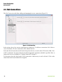
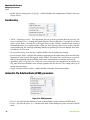
3. The installation process will be started. Click Next to install the software. Click Cancel to quit,
Figure 1-1. Installation
10
www.javad.com
Getting Started
Getting Connected
Uninstalling NetHub
1.1.3. Uninstalling NetHub
To uninstall NetHub use the Add and Remove Programs from the Control Panel.
1. Open the Control Panel, then Add or Remove Programs tool. Find NetHub, and click Change/
Remove.
2. This will uninstall NetHub.
1.2. Getting Connected
1.2.1. Starting NetHub
NetHub can be launched, as any other Windows program, for example, with the StartAll Programs
JAVAD GNSS NetHub.
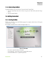
Once NetHub is launched, the Start window will appear (Figure 1-2):
Figure 1-2. Start window
• Get started - opens the software user manual
• Visit NetHub page - opens software page on JAVAD GNSS web site
• Visit JAVAD GNSS web site - opens www.javad.com
www.javad.com
11
Getting Started
Getting Connected
Establishing connection
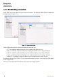
1.2.2. Establishing connection
Click Hub Connections, then Add new Connection button. The dialog window with the connection
settings appears (Figure 1-3).
Figure 1-3. Connection window
Click the drop-down list box and select the desired connection type:
•
•
•
•
•
TCP - to establish connection between your computer and remote receiver;
SER - to establish a connection between your computer and the receiver using serial ports;
USB - to establish a connection between your computer and the receiver using USB port;
CAN - to establish a connection between your computer and the receiver using CAN ports;
REMOTE - to establish a connection between your computer and the remote receiver.
To connect to the receiver, click Ok. If your connection settings are correct, a new receiver will be added
in the navigation bar.
Please see below the detailed description of the connection settings window.
12
www.javad.com
Getting Started
Getting Connected
TCP connection
1.2.3. TCP connection
This method is used when you have an existing local area network (LAN) consisting of a group of
computers and network communication devices interconnected and a JAVAD GNSS receiver that you
want to place on this LAN. This method is also used to connect a JAVAD GNSS receiver directly to the
Internet and access this receiver from a remote PC, connected to the Internet.
If the TCP connection will be used, set the following parameters (Figure 1-4):
Figure 1-4. TCP connection settings
• Address - Host name or IP address of the receiver;
• Port - TCP port of the receiver. This is the port on which the receiver listens for telnet-like
connections. The receiver allows up to five simultaneous telnet-like connections.
• Logical port - one of the five logical port mapping (a, b, c, d, e). If the value is empty, then the
connection is established with the first free logical port;
• Password - an arbitrary sequence of characters (if you the receiver is in the _ISECURE mode, you
may simply leave this field blank)
• TSL/SSL - Enables/disables the encrypting with cryptographic protocols that provide
communications security over the Internet. This parameter should correspond with receiver’s
settings.
1.2.4. Serial connection
To establish a connection between your computer and the receiver using serial ports, follow these steps:
1. Connect one of the available receiver’s port (usually A) to a communication port on the computer
using a Receiver-to-Computer RS-232 serial cable.
2. Supply power to the receiver, then turn it on.
If the serial connection will be used, set the following parameters (Figure 1-5):
Figure 1-5. Serial port connection settings
• Port - serial port from a list of the ports available in the system the receiver is connected to;
www.javad.com
13
Getting Started
Getting Connected
USB connection
•
•
•
•
•
Parity - method for determination of transmission errors;
Baud rate - data transfer rate
Data bits - number of data bits in a symbol;
Stop bits - duration of the stop bit;
Rts enable - Data Control.
1.2.5. USB connection
Before connecting a USB equipped JAVAD GNSS receiver with PC’s USB port, make sure that you have
the USB Port option enabled in the receiver and the JAVAD GNSS USB driver installed on the computer.
This driver is available on the JAVAD GNSS website: www.javad.com.
Installing Driver
The driver installation procedure varies slightly depending on the operating system used. In general, the
installation procedure is as follows:
1.
2.
3.
4.
Visit the JAVAD GNSS website. Download the USB driver.
Unpack the archive into a separate, empty folder.
Connect the receiver to the computer through the supplied USB cable. Turn the receiver on.
Windows will automatically detect the new hardware device. Follow the on-screen instructions to
finish installation process.
After Windows finishes installing the driver, you will be able to connect the receiver and the computer via
USB ports.
Click the Refresh button on the Hub Connections page to refresh the list of the available USB ports.
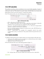
If the USB connection will be used, set the following parameters (Figure 1-6):
Figure 1-6. USB connection settings
Select the required ID from the list.
14
www.javad.com
Getting Started
Getting Connected
CAN connection
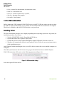
1.2.6. CAN connection
Before connecting a CAN equipped JAVAD GNSS receiver with PC’s, make sure that you have the CAN
Port option enabled in the receiver. If the CAN connection will be used, set the following parameters
(Figure 1-7):
Figure 1-7. CAN connection settings
• Channel - allows selecting channel;
• Baud rate - data transfer rate;
Connection via CAN allows you to connect multiple receivers, which are in the same CAN network. In
this case, the incoming (In) and outgoing (Out) identifiers should not overlap the ranges. All devices are
one of CAN networks operate at one speed. The software supports only Kvaser (http://kvaser.com)
adapters.
1.2.7. REMOTE Connection
This mode allows to connect to NetHub the receiver connected to the remote PC using COM-port, USB,
or CAN. To establish such connection type, the Javad Net Remote Connector application should be
started on remote PC. See the detailed description in the JavadNet Remote Connector user manual.
www.javad.com
15
Getting Started
Getting Connected
Closing NetHub
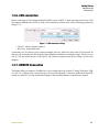
1.2.8. Closing NetHub
Clicking on the Disconnect button will result the disabling of the connection, and the software will not
connect to the receiver (Figure 1-8).
Figure 1-8. Disconnecting
The closing process may take some minutes, because the software is preparing and saving the tasks for
the next session. All settings and receiver parameters will be saved and activated automatically starting
the next session.
16
www.javad.com
Chapter 2
SERVER CONFIGURATION
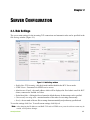
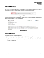
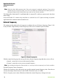
2.1. Hub Settings
The server main settings for the incoming TCP connections and automatic tasks can be specified in the
Hub Settings window (Figure 2-1).
Figure 2-1. Hub Settings window
• Enable Raw TCP Incoming - this check mark enables/disables the RCV Server mode.
• NTRIP Caster - Parameters for NTRIP service access.
• Administrator E-mail - the email address which will be displayed in Head admin email for RCV
clients, connected to NetHub via Telnet.
• Default data folder - clicking the Browse button the default directory for data storage can be specified.
• Concurrently executing tasks - maximal number of the tasks are executing concurrently.
• Sort by - the sort mode of the raw files to arrange them automatically and perform any specified task.
To save the settings click Save. To recall current settings click Refresh.
Note: After changing the IP addresses and RAW TCP and/or NTRIP server ports the software restart may be
needed, to accept these changes.
www.javad.com
17
Server Configuration
Hub Connections
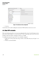
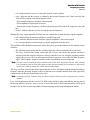
2.2. Hub Connections
The Hub Connections tab allows adding and managing the server connections (Figure 2-2).
Figure 2-2. Hub Connections
In the picture above the current connections are displayed. To add new connection click Add new
connection button. The new connection will be added to the list.
Select the desired connection mode from the drop-down list box, it can be either TCP, Serial, USB, CAN,
or RCV connection. For each connection mode the appropriate parameters should be specified. How to
connect the receiver to NetHub see “Getting Connected” on page 11.
To disconnect clear the check mark. If the connection is unnecessary it can be deleted. Click on the
connection in the list, the button Delete appears.
18
www.javad.com
Server Configuration
NTRIP Settings
Setup Base
2.3. NTRIP Settings
The NTRIP caster area of the General settings window allows configuring the receiver to send the
corrections via NTRIP. To activate NTRIP Caster enable the appropriate check mark.
Figure 2-3. NTRIP Caster
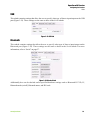
To add the mountpoint to the mountpoint list, setup the receiver as a base. refresh the information after
adding new base to the list, to view new mountpoint.
Figure 2-4. Mountpoint
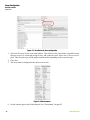
2.3.1. Setup Base
To setup the base follow the instructions below:
1. Insert the exact coordinates of the base as described in “Base” on page 51.
2. Open the Base/Rover tab and select the Use receiver a reference base check mark. Set other
parameters such as country, city, network name, and select the allowed corrections from the list
(Figure 2-5 on page 20):
www.javad.com
19
Server Configuration
Raw TCP accounts
Setup Base
Figure 2-5. Base/Rover tab. Base configuration
3. Click Save.
Now this base can be used for sending the corrections in NTRIP and direct to the rovers as well.
2.4. Raw TCP accounts
There are situations, when there is no way to get connected to the receiver. It can be because receiver
doesn’t have static IP address, etc. In such case the TCP RCV client mode can be used. The receiver
should be connected to Internet via Ethernet connector or via GPRS.
To establish such connection type, the RCV server should be configured:
1. Enable TCP Incoming on the Hub Settings window, set the address and port (see Figure 2-1 on
page 17).
2. Click Save, and restart NetHub.
20
www.javad.com
Server Configuration
Raw TCP accounts
Setup Rover
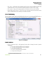
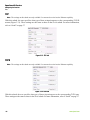
3. In the Raw TCP accounts page add new account:
Figure 2-6. TCP accounts
4.
5.
6.
7.
Enter description and password. Click Save.
To delete account, highlight it and click Delete.
The Refresh button updates the list of the saved account.
How to configure RCV client mode for your receiver, see receiver’s user manual (RCV client).
The RCV client can be configured via Tracy Software. See tracy Software Manual for details.
This type of the connection can be used to transfer the corrections to the rover. Unlike NTRIP caster this
mode allow the user to re-configure the base receiver, its files can be downloaded, the receiver is visible
on the map.
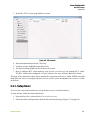
2.4.1. Setup Rover
To receive the correction from the base, set up the base receiver as described above.
To setup the base follow the instructions below:
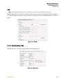
1. Open the Base/Rover tab and select User receiver as rover.
2. Select the earlier configured base from the list and correction type (Figure 2-7 on page 22):
www.javad.com
21
Server Configuration
Raw TCP accounts
Setup Rover
Figure 2-7. Base/Rover tab. Base configuration
3. Select the free port for the correction redirect. The redirect of the corrections is needed because
the port receiver is connected trough is busy and cannot be used. Select one of free receiver’s
ports. Thew decoder type will be applied automatically depending on the correction type.
4. Click Save.
5. The rover status is displayed in the Measurements tab.
Figure 2-8. Measurements
6. Set the solution type in the Positioning tab. See “Positioning” on page 45.
22
www.javad.com
Server Configuration
Task Templates
Setup Rover
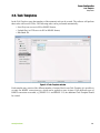
2.5. Task Templates
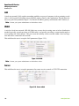
In the Task Templates page the templates of the automatic task can be created. The software will perform
these tasks with receiver’s files. The following tasks can be performed automatically:
• Save file(s) on a server in JPS or RINEX format;
• Upload file(s) to FTP server in JPS or RINEX format;
• Run Batch file.
Figure 2-9. Tasks Templates window
Each template may consist of the different number of actions. But for one Task Template it is possible to
set only one RINEX conversion type, which can be applied to some Actions. If the different types of
RINEX conversion are needed, e.g. RINEX 2.11 and RINEX 2.12, the additional Task Template should
be created.
www.javad.com
23
Server Configuration
Task Templates
Save
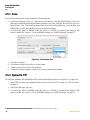
2.5.1. Save
To set up the automatic file saving, perform the following steps:
1. Specify the directory1 (Save to). Click the Browse button to select the desired folder. To the save
path can be added the following predefined variables: year, date, GPS day, Receiver ID or receiver
name (Figure 2-10). This allows arranging the files to the specified folders (e.g. sort the Raw and
RINEX files by GPS day and place them to the different folders).
2. To convert the file(s) to RINEX enable the Convert to RINEX, to compress the file(s) to ZIP
archive, enable ZIP compress. To set up RINEX settings, see “RINEX Settings” on page 27.
Figure 2-10. Task Template: Save
3.
4.
5.
6.
Click Save Template.
To add more actions click Add new Action button.
To delete action, click Delete Action button.
To delete the whole template, click Delete Template button on the bottom.
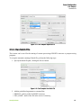
2.5.2. Upload to FTP
To set up the automatic file uploading to FTP, perform the following steps (see Figure 2-11 on page 25):
1. Enter FTP account or open predefined one. How to create new FTP account see “FTP Accounts”
on page 27.
2. Specify the directory (Save to).
3. To convert the file(s) to RINEX enable the Convert to RINEX, to compress the file(s) to ZIP
archive, enable ZIP compress. To set up RINEX settings, see “RINEX Settings” on page 27.
1. By default the path is the same which is specified in Hub Settings window described on page 17.
24
www.javad.com
Server Configuration
Task Templates
Run Batch File
Figure 2-11. Task Template: Upload to FTP
2.5.3. Run Batch File
This Action can be used for the starting of custom processing of RINEX converter or postprocessing
programs.
To set up the automatic running of batch file, perform the following steps:
1. Specify the batch file path, clicking the Browse button.
Figure 2-12. Task Template: Run Batch File
2. Add the predefined arguments to command line:
• PROFILE - path to profile for RINEX converter;
• FILE_NAME - name of the file in the receiver’s memory;
www.javad.com
25
Server Configuration
Task Templates
Run Batch File
•
•
•
•
JPS_FILE - path to file downloaded from receiver’s memory;
DATE - start date of the JPS file recording;
GPS_DAY - GPS day of the JPS file recording
RECEIVER_ID and RECEIVER_NAME - ID and Name of the receiver, specified by receiver
configuration (see “Settings” on page 37);
• SLANT, ANTENNA_TYPE, ANTENNA_HEIGHT - parameters of the antenna, specified in the
Site Configuration (see “Settings” on page 37).
On the Figure 2-13 is template with three actions (save file on server, upload file to FTP-server, and run
batch file) depicted:
Figure 2-13. Task Template
This template means each file of the receiver will be converted to RINEX with defined settings, then
compressed to ZIP, and saved in the specified folder, at the same time this file without conversing and
compression will be uploaded on FTP server and the batch file will run.
Note: The file(s) will be only one time converted to RINEX. If the RINEX converting with different parameters
is needed, should be created other template.
This template can be applied to every connected receiver.
26
www.javad.com
Server Configuration
FTP Accounts
RINEX Settings
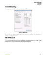
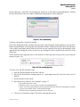
2.5.4. RINEX Settings
To setup parameters for RINEX converting, click on the RINEX settings button.
Figure 2-14. RINEX settings
The fields and check marks correspond to jps2rnx.exe. command line arguments. The command line is
displayed on the top of this window.
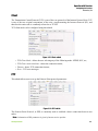
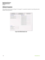
2.6. FTP Accounts
FTP Accounts tab allows to set up the FTP parameters for Task template (Action). To add new account
click the Add New FTP account button. Enter the standard FTP parameters.
www.javad.com
27
Server Configuration
FTP Accounts
RINEX Settings
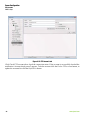
Figure 2-15. FTP Accounts tab
Click Check FTP account tab to check the connection status. If the account is successfully checked the
notification “Account check passed” appears. To delete account click the Delete FTP account button, to
update the accounts list click the Refresh list button.
28
www.javad.com
Server Configuration
Email Notifications
RINEX Settings
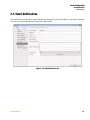
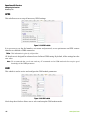
2.7. Email Notifications
The notification system allows duplicating the log messages to the email addresses, specified in this tab.
Contact your system administrator about the email settings.
Figure 2-16. Email Notifications tab
www.javad.com
29
Server Configuration
Map
RINEX Settings
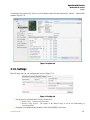
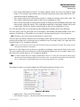
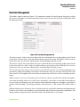
2.8. Map
On the map displays the location of the connected receivers. Click on the receiver location to see the
receiver name and its coordinates.
Figure 2-17. Map tab and position of the connected receivers
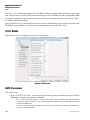
2.9. Hub Logs
The server log with messages, actions, and errors registration.
30
www.javad.com
Server Configuration
Action Logs
RINEX Settings
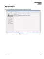
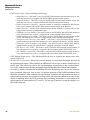
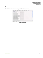
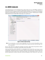
2.10. Action Logs
The Action logs tab allows tracking the performance of the automatic tasks.
Figure 2-18. Action logs tab
www.javad.com
31
Server Configuration
Action Logs
RINEX Settings
32
www.javad.com
Chapter 3
OPERATION WITH RECEIVER
NetHub allows you to manage and control the GNSS receivers manufactured by JAVAD GNSS, and it has
a user friendly interface.
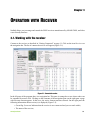
3.1. Working with the receiver
Connect to the receiver as described in “Getting Connected” on page 11. Click on the item Receivers on
the navigation bar. The list of connected receivers will appear (Figure 3-1).
Figure 3-1. Connected receiver
In the left pane of the program there is a navigation bar. This pane is arranged as a tree whose nodes can
be expanded by mouse click. Clicking on the elements of the navigation pane on the right pane a page
with relevant content appears. In this case, the active element remains selected. On the right pane the
following information about receiver(s) is displayed (Figure 3-2):
• Green flag Connected indicates that the receiver is now connected and you can work with it;
• The name of the receiver;
www.javad.com
33
Operation with Receiver
Working with the receiver
Measurements tab
• Rec - the current files, which are logging;
• Receiver’s memory capacity;
• Connection type
Figure 3-2. Connected receivers list
Point the receiver’s name on the left pane, a tooltip will popup with detailed information about the
receiver will appear.
When you click on the name of the receiver, the status page with detailed information for the selected
receiver will be displayed (Figure 3-1 on page 33). This page shows the appearance of the receiver, its
characteristics, the available connections, table of satellites. Tabs available Sky Plot, Orientation,
Options, Settings.
To view and upload options of the receiver use the tab Options. To upload a new options file, click on
Upload, and select the options file.
Below are described tabs on the right pane.
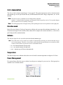
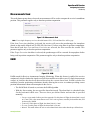
3.1.1. Measurements tab
Measurements tab (Figure 3-1 on page 33) displays the basic tracking information (parameters) for the
locked satellites. It shows the receiver target point current position, receiver coordinates and the timefrequency parameters describing the behavior of the receiver’s local oscillator.
The various navigation information is displayed, specifically:
• Geodetic coordinates1
- Lat, Lon – latitude/longitude;
- Alt – ellipsoidal height.
• Velocity 2D – (magnitude of the) velocity (m/s).
• Position RMS – rms position error2 (m).
• Velocity RMS – rms velocity error* (m/s).
• PDOP – Position dilution of precision.
• Solution type:
1. These geodetic coordinates are computed in WGS 84 regardless of the current value of /par/pos/datum/cur.
2. More precisely, this is the square root of the trace of the position error variance-covariance
34
www.javad.com
Operation with Receiver
Working with the receiver
Measurements tab
- Standalone/ Code differential/ RTK float / RTK fixed/WAAS DGPS differential
• Receiver time shows the receiver’s current time within day. This value is taken from the message
[~~]. For more information about [~~], see the GREIS Reference Manual.
Note: Currently the message [~~] reports the time within day in the GPS time scale only.
• Receiver date shows the receiver’s current date as specified in the corresponding [RD] message.
• Clock offset describes the time derivative of (Tr – Trr), where Tr designates the receiver time, Trr
designates the receiver reference time. For more information about Tr and Trr, see the GREIS
Reference Manual. This parameter is obtained from the [DO] message and is expressed in ppm.
• Osc. offset is derived from the message [OO] and it is expressed in ppm. The parameter describes
the difference between the VCO’s nominal and quiescent frequencies.
• Tracking time is the time elapsed since the last complete loss-of-lock event in the receiver’s C/A
channels as specified in the corresponding [TT] message.
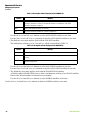
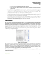
The tracking parameters displayed in table are described below:
Table 3-1. Tracking Parameters
Parameter
Description
*
Num
GPS SV PRN. If the character “*” is shown next to PRN in the column, this means that
almanac data are unavailable for the corresponding satellite.
Galileo PRN. SBAS PRN.
GLONASS SV Orbital Slot Number. If the character “*” is shown next to Sn in the column,
this means that almanac data are unavailable for the corresponding satellite.
GLONASS SV Frequency Number.
EL
Elevation angle in degrees.
AZ
Azimuth in degrees
CA/L1
Signal-to-noise ratio (C/N0) in the C/A channel [dB*Hz]
P/L1
Signal-to-noise ratio (C/N0) in the P1 channel [dB*Hz]
P2/2
Signal-to-noise ratio (C/N0) in the P2 channel [dB*Hz]
Track time
Time elapsed since the last loss-of-lock in the C/A channel for the corresponding satellite.
This time is given in minutes or, if the symbol “:” is specified in the column, in seconds.
SS
Satellite navigation status. For a complete description of the satellite navigation status
structure, see Appendix. If a satellite is not used in position computation, its SS flag will be
set to “-“. Otherwise “+” will be displayed.
Note: Empty cells will be displayed everywhere in the panels where the corresponding parameters are
unavailable.
www.javad.com
35
Operation with Receiver
Working with the receiver
Sky Plot tab
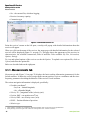
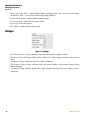
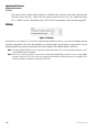
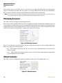
3.1.2. Sky Plot tab
The Sky Plot tab shows graphic representation of the satellite positions in the sky (Figure 3-3):
Figure 3-3. Sky plot tab
Each concentric circle represents the elevation angle above the horizon. The outermost circle corresponds
to 0 degrees above the horizon. The center of the sky plot represents 90 degrees above the horizon. The
dotted circle shows the position computation elevation mask angle.
The flags on the right allow the user to select the desired system to be displayed on the right plot.
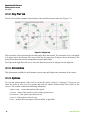
3.1.3. Orientation
This information available for multi-antenna systems only and displays the orientation of the system.
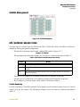
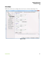
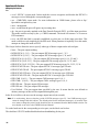
3.1.4. Options
To view and upload options of the receiver use the tab Options (Figure 3-4 on page 37). Here you can
check the status of your receiver’s options and load new Option Authorization Files (OAFs) to the
receiver. This window contains the following information:
•
•
•
•
•
36
Option name – a name/description of the option
Current – shows if the option is in force at the present or not
Purchased – if the option is purchased or not
Leased – if the option is leased or not
Date – the date the leased option will be disabled, if applicable
www.javad.com
Operation with Receiver
Working with the receiver
Settings
To upload a new options file, click on Upload button, and select the options file. Refresh – Updates the
window (Figure 3-4).
Figure 3-4. Options tab
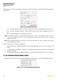
3.1.5. Settings
In the Settings tab you can configure the receiver (Figure 3-5).
Figure 3-5. Settings tab
• Set up the receiver name in the Display Name field.
• Display Name - Connected receiver name.
• Resource usage priority - The priority of the channel usage. It can be file downloading or
correction transfer.
• Setup the site configuration parameters used in the RINEX-conversion:
www.javad.com
37
Operation with Receiver
Working with Files
Settings
• Site Name – The site identification string (up to 20 alphanumeric characters).
• Antenna Status – This control allows the user to define whether the receiver antenna is in motion
or is motionless.
• Antenna Height – The height of antenna, measured from the survey marker to the measuring
mark of antenna. The measuring mark is the antenna reference point (ARP) if you use the vertical
height or a known measuring mark (usually antenna edge) on the antenna if you use the slant
height.
• Slant – Enable this checkbox if you measure the slant height. Otherwise, leave it blank.
• Antenna Type – Select the type of antenna you use.
• Tasks - Specified Task Template for the selected receiver.
3.2. Working with Files
Select Files in the navigation pane (Figure 3-6).
Figure 3-6. Files
38
www.javad.com
Operation with Receiver
Working with Files
Settings
On the right pane a list of files will be displayed. Select one or more files to download them by clicking
the Download button. The new window with downloading progress will be displayed.
Figure 3-7. File is downloading
To delete selected files, click Delete button.
Files in the destination folder will have the same names and extensions as the original receiver log files.
Before downloading the current log file in the destination folder, NetHub will check if there already exists
a file with the same name in this folder. In the first case the contents of the log file downloaded will be
appended to the existing file. In the second case, the existing file will be replaced with a new file of the
same name.
On the bottom of the right pane there is the interface to start/stop data writing to the receiver internal
memory (Figure 3-8):
Figure 3-8. File recording interface
To create a new log file, take these steps:
1. Enter the desired filename in the Name edit box.
2. Specify the desired data recording interval (i.e., data update interval) in the Recording interval
edit box.
3. Set the desired Elevation mask.
4. Specify the Site parameters. See “Settings” on page 37.
• Specify the desired Site Name.
• Select the correct Antenna Status from the corresponding list box.
• Set the Antenna Height parameter and select/deselect the Slant check box depending on whether
you have specified the slant or vertical antenna height.
• Select the correct antenna type from the Antenna Type box.
5. Click Start to start data writing. Click Stop to interrupt this process.
www.javad.com
39
Operation with Receiver
Configuring the Receiver
Settings
3.3. Configuring the Receiver
Select the desired receiver in the navigation pane, and expand the elements of the receiver by double
clicking on the Receiver. Select Parameters item (Figure 3-9).
Figure 3-9. Receiver parameters
40
www.javad.com
Operation with Receiver
Configuring the Receiver
General tab
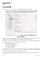
3.3.1. General tab
The General tab is shown on the Figure 3-9 on page 40. The general parameters such as elevation mask
and antenna type can be specified in this tab, and information about the voltage, temperature, etc. can be
checked.
Note: The basic receiver’s parameters can be changed in the right pane.
Symbol “*” indicates that the parameter was changed, but not accepted by receiver. To accept the changes
and save them in receivers memory click Apply.
Note: The tooltip popup menu will appear always when pointing the cursor on the parameter on the right pane.
Elevation mask
In the Elevation Mask for Position Computation edit box, the user enters the minimum elevation (i.e., the
elevation mask angle) for the satellites whose data will be output to the current terminal (i.e., the receiver
port being used for communication).
Antenna
The Antenna Input list box is used to select the desired antenna type:
Note: Note that some receiver models are capable of automatically detecting an external antenna only at
receiver start-up time. Therefore, if one wants to switch from the internal antenna to an external one while
in auto, he/she will have to power the receiver off and then back on.
• int – the internal antenna is being used.
• ext – an external antenna is being used.
• auto – antenna type will detect automatically.
Temperature
The Board temperature indicator shows the receiver board’s current temperature in degrees of Celsius.
Power Management
Five group boxes allow the user to adjust/view the power settings for your receiver. Each group box
contains a set of related controls.
Figure 3-10. Power Management
www.javad.com
41
Operation with Receiver
Configuring the Receiver
General tab
• Battery Charging Mode - enables/disables battery charging mode: Off – receiver will not charge
the batteries. Auto – receiver will automatically charge batteries.
• Enable Power Output - enables/disables power output;
• Low power mode - turns on/of low power mode;
• Power Off - turns on/of power;
• Sleep Mode - enables/disables sleep mode.
Voltages
Figure 3-11. Voltages
• The External Power Voltage indicator shows the external power supply's voltage.
• The Receiver Board Voltage indicator shows what is the actual voltage presented on the receiver
board.
• The Battery Voltage indicators show the voltage on batteries.
• The Charger Output Voltage indicator shows the output voltage of the internal charger during
battery charging.
• The Output Voltage indicator displays the output voltage on the first pin of each of the receiver’s
serial port.
42
www.javad.com
Operation with Receiver
Configuring the Receiver
TriPad
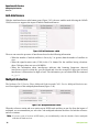
3.3.2. TriPad
In this tab (Figure 3-12), the user can configure receiver parameters, which relate to TriPad (user simple
interface):
Figure 3-12. TriPad tab
File a, File b
In the fields File a, File b can be specified current log-file name, message output period, etc.
• Current log-file edit box allows the user to specify the prefix of the log file, which will be saved
into receiver memory during survey.
• In the Output Epochs Counter box the number of outputted epochs is shown.
• In the Implicit Message Output Period edit box the output period for the implicit messages can be
specified. This parameter specifies the interval of outputting messages into the log-file when data
logging is activated with the TriPad or through the AFRM.
• Elevation Mask for Measurements Output (the minimum elevation angle for the satellites whose
data will be put in the receiver files logged when pressing FN).
• Satellites Number Mask for Position computation - Satellites with elevations lower than this mask
will be excluded from position computation.
• File Name Prefix - this setting specifies what prefix will be added to the names of the receiver files
created via MinPad, (i.e., by pressing FN). The prefix can be up to 20 characters long. Default is
log.
www.javad.com
43
Operation with Receiver
Configuring the Receiver
TriPad
• Enable Implicit Management of Specific - enables/disables the management of Implicit Message
Output Period.
Function Key
• TriPad “Funnybone Action - This drop-down list box is used to program how the receiver will
react to clicking FN (i.e., keeping the button depressed for less than one (1) second). In led blink
mode switch mode, clicking FN will toggle between the TriPad’s standard and extended
information modes. In occupation mode switch you click FN to get the receiver to insert into the
corresponding log file a message indicating that the occupation type has been changed from static
to kinematic, or vice versa.
• Turn Data Recording on at Startup - enables/disables data recording on at startup,
• Initial Dynamic Mode - specifies the starting occupation type descriptor that will be inserted at the
beginning of each receiver files logged via the TriPad. You select static and kinematic to specify
that the corresponding log file will start with a static and kinematic occupation, respectively.
• Appending data to a specific file - If the new receiver data are to be appended to an existing log
file, enter the desired filename in the Always append to the file edit box. The setting can be up to
twenty characters long.
• Toggle Automatic Rotation Mode - enables/disables Automatic File Rotation Mode.
Automatic File Rotation Mode (AFRM) parameters
Figure 3-13. AFRM parameters
• Period – specifies the time duration of each of the multiple log files created in AFRM mode.
• Phase – specifies the phase (i.e., constant time shift) of the multiple log files created in AFRM
mode.
44
www.javad.com
Operation with Receiver
Configuring the Receiver
Positioning
• Files (total) – specifies how many multiple log files must be created in AFRM until this mode
automatically turns off. Zero means that an unlimited number of log files will be created.
• Files (remain) – shows you how many log files are left for the receiver to create in AFRM.
• Enable Oldest Log-file removal – if active, the receiver will remove the least recent files if no free
space is available in the receiver memory to record the current file.
3.3.3. Positioning
This tab contains various controls and fields that allow the user to set elevation and PDOP masks, to
select satellites to track, and to specify what measurements to use in position computation.
Figure 3-14. Positioning tab
Enable Solutions
• Position Computation Mode - this drop-down list box allows selecting the mode of position
computation:
•
•
•
•
•
pd -carrier phase differential (RTK) with fixed ambiguities
pf - carrier phase differential (RTK) with float ambiguities
cd- code differential (DGPS) mode
wd - wide area code differential mode (WDGPS)
sp - single point positioning mode1
1. Also known as “absolute positioning”, “stand-alone positioning” or simply “point positioning”
www.javad.com
45
Operation with Receiver
Configuring the Receiver
Positioning
• If the Enable Code Differential Position is activated and the rover receiver is running in RTK Float
or RTK Fixed mode and is unable to obtain an RTK solution at the current epoch, it will output the
current code differential position for the unavailable RTK solution.
Note: If the DGPS (Code Differential) checkbox is enabled and a DGPS solution cannot be obtained, you can
instruct the receiver to output single-point position for the unavailable differential. For this, enable the
Standalone checkbox.
Note: Code differential mode requires broadcasting the corresponding DGPS (not RTK) messages from the
reference receiver and accepting them on the rover receiver. If any of these requirements are not met, then
enabling the DGPS (Code Differential) checkbox will not have any effect.
Positioning Masks
Figure 3-15. Position Masks
• In the Elevation mask edit box, you specify the elevation mask angle for the satellites used in
position computation. The receiver will not use the satellites below the specified elevation mask to
compute the position. The default value is 5 degrees.
• In the PDOP mask edit box, you specify the threshold value of PDOP that disables position
computation. If PDOP exceeds this mask during a period of time, the receiver's position will not
be computed over the corresponding epochs. The default value is 30.
Positioning Systems
Select the GPS, GLONASS, Galileo, and SBAS checkboxes if it is desired that the corresponding satellite
constellations to be used in position computation.
Note: However, the selected satellite constellation will indeed be used in position computation only if the
corresponding Satellites used in pos. checkbox from the Satellite management panel is selected as well.
46
www.javad.com
Operation with Receiver
Configuring the Receiver
Positioning
Satellite Management
Figure 3-16. Satellite Management
GPS | GLONASS | GALILEO | SBAS
Use these tabs to explicitly specify which of the GPS, GLONASS, Galileo and SBAS satellites are
enabled for tracking and position computation.
• The first tab, as its name implies, deals with the GPS satellites (Figure 3-17).
Figure 3-17. GPS tab
The tab displays the following columns, prn, lock and use, which are described in Table 3-2.
Table 3-2. Description of Data Displayed in the GPS Tab
Notation
Meaning
prn
GPS satellites’ pseudo-random noise code numbers.
lock
Checkmarks in this column indicate that the corresponding satellites are enabled for
tracking.
use
Checkmarks in this column indicate that the corresponding satellites are enabled for
position computation.
Use the All to lock and All to use buttons to select all GPS satellites at one time.
Use the None to lock and None to use buttons to deselect all GPS satellites at one time.
• The second tab, as its name implies, deals with the GLONASS satellites.
Satellite Numbering
For user convenience, GLONASS satellites can be displayed ordered either by their Frequency Channel
Number or by the Slot Number. The tab displays columns, fcn/sat, lock and use, which are described in
Table 3-3.
www.javad.com
47
Operation with Receiver
Configuring the Receiver
Positioning
Table 3-3. Description of Data Displayed in the GLONASS Tab
Notation
Meaning
fcn/sat
GLONASS satellites’ frequency channel numbers, if the Frequency Channel
Number checkbox is selected. GLONASS satellites’ slot numbers, if the Slot
Number checkbox is enabled.
lock
Enable GLONASS satellites for tracking.
use
Use this GLONASS satellite for position computation.
Use the All to lock and All to use buttons to select all GLONASS satellites at one time.
Use the None to lock and None to use buttons to deselect all GLONASS satellites at one time.
• The third tab, as its name implies, deals with the GALILEO satellites.
The tab displays columns, prn/sat, lock and use, which are described in Table 3-4.
Table 3-4. Description of Data Displayed in the GALILEO Tab
Notation
Meaning
prn
GALILEO satellites’ pseudo-random noise code numbers.
lock
Checkmarks in this column indicate that the corresponding satellites are enabled for
tracking.
use
Checkmarks in this column indicate that the corresponding satellites are enabled for
position computation.
Use the All to lock and All to use buttons to select all GALILEO satellites at one time.
Use the None to lock and None to use buttons to deselect all GALILEO satellites at one time.
• The fourth tab, as its name implies, deals with the WAAS/EGNOS satellites.
A WAAS-enabled JAVAD GNSS receiver allows simultaneous tracking of two WAAS satellites.
Either of the WAAS satellites is allocated its own channel.
Use the All to lock and All to use buttons to select all SBAS satellites at one time.
Use the None to lock and None to use buttons to deselect all SBAS satellites at one time.
48
www.javad.com
Operation with Receiver
Configuring the Receiver
Positioning
Measurements Used
This radio button group shows what code measurements will be used to compute the receiver's standalone
position. This parameter applies only to absolute position computation.
Figure 3-18. Measurements Used
Note: For a single-frequency receiver, the radio buttons P/L1, P/L2 and Iono-Free will be gray.
If the Iono-Correction checkbox is selected, the receiver will correct the pseudoranges for ionosphere
(based on the model defined in ICD-GPS-200, Revision C) before using them in position computation.
Note that if both Iono-Free and Iono-Correction are selected, the first overrides the second. This
parameter applies only to absolute position computation.
If the Tropo-Correction checkbox is selected, the pseudoranges will be corrected for troposphere before
being used in position computation. This parameter applies only to absolute position computation.
RAIM
Figure 3-19. RAIM
RAIM stands for Receiver Autonomous Integrity Monitoring. When this feature is enabled, the receiver
continuously checks whether the signals received from satellites are usable or not. If a fault (measurement
outlier) in satellite data has been detected based on the current alarm limit, RAIM excludes this
satellite(s) from the positioning calculations, thereby allowing the receiver to continue providing correct
position information without an interruption in the service.
• The RAIM Mode if turned on, activates the RAIM algorithm.
• With the Alarm setting, the user specifies alarm limit mode. The alarm limit is a threshold value
for the horizontal radial error. There are three pre-defined limits and one that is specified
manually:
• Non-precision stands for Non-precision approach. For this phase of flight, the alarm limit is equal
to 0.3 nmi. This value means that an error of 0.3 nmi or greater, caused by bad satellite data, will
be detected by RAIM.
• Terminal. For this phase of flight, the alarm limit is 1.0 nmi.
• En route. For this phase of flight, the alarm limit is 2.0 nmi.
• Manual. This mode allows the user to select alarm limit values other than the pre-defined ones.
www.javad.com
49
Operation with Receiver
Configuring the Receiver
Positioning
• The Alarm limit for Manual Mode edit box is available only if one has selected the Manual mode
from the Alarm list box. Values the user enters in this edit box can vary within the range
10.0…10000.0 meters. The default value is 555.6 and it corresponds to Non-precision approach.
Datum
Figure 3-20. Datum
From the Current Datum for Position Computation drop-down list box, you select the datum used in
position computation. Once the desired datum is selected and the Apply button is pressed, the receiver
begins producing its position expressed in the selected datum. The default datum is WGS 84.
Note: Currently JAVAD GNSS receivers support more than 200 datums. For a list of the supported datums, refer
to the GREIS Reference Manual.
Note: The receiver position, which is expressed in a datum other than WGS 84, may be viewed using NMEA
messages such as GGA, GLL and so on. Position-related JAVAD GNSS messages (for example [PV])
always contain the coordinates computed in WGS 84.
50
www.javad.com
Operation with Receiver
Configuring the Receiver
Base
3.3.4. Base
With the Base tab, the user can configure the receiver for use as a reference station (Figure 3-21).
Figure 3-21. Base
www.javad.com
51
Operation with Receiver
Configuring the Receiver
Base
In the Reference Position area (Figure 3-22) the user enters the geodetic coordinates of the base antenna’s
phase center.
Figure 3-22. Reference Position area
• Lat – Antenna latitude in degrees, minutes, and seconds format with a hemisphere letter (N or S).
• Lon – Antenna longitude in degrees, minutes, and seconds format with a hemisphere letter (E or
W).
• Alt – Antenna height above the ellipsoid, in meters.
Note: The reference geodetic coordinates specified in this tab will relate to the antenna L1 phase center. To
account for the offset between the L1 and L2 antenna phase centers, use the parameter L1 to L2 Antenna
Phase Center offsets.
Note: If the coordinates entered are expressed in a datum other than WGS 84, which is default, ensure that the
correct datum ID is selected.
There are three ways to enter the coordinates:
1. Type in the precise latitude/longitude and ell. height manually (use the Lat, Lon and Alt edit
boxes).
2. Use the absolute coordinates averaged over the specified time interval (with the Averaged and
Avg.Span controls).
3. Use the instant absolute coordinates from the receiver (by pressing the Get from receiver button).
L1 to L2 Antenna Phase Center offsets
Use these fields if you need to account for the difference between the L1 and L2 antenna phase offsets.
Figure 3-23. L1 to L2 Antenna Phase Center offsets
52
www.javad.com
Operation with Receiver
Configuring the Receiver
Base
RTCM Settings
The Station ID edit box allows the user to assign a separate station ID to each reference station working in
the area. On the rover side, this ID allows easy identification of the reference station whose RTCM
messages are being received by the rover receiver. This ID must be an integer from 0 (default) to 1023.
With the Max. number of Satellites edit box, the user specifies the maximum number of satellites allowed
for use in RTCM messages types 18 through 21. A 0 means that all of the available satellites will be
included in the above mentioned RTCM message types. If an RTK system has a slow modem (the baud
rate is less than 9600 bps), it is recommended to restrict the number of satellites included in these
messages. The limitation allows the user to reduce the amount of data sent by the base station, which
helps to avoid the data link overload. If the actual number of satellites in sight exceeds the value entered
in this edit box, the RTCM messages will include data only from the satellites with higher elevations and
the number of satellites included in the RTCM messages will not be greater than that specified in the edit
box.
The Health list box is intended to define the reference station status:
• Good – station is operating normally.
• Bad – station is not working normally.
• Unknown – station health status is unknown.
With the Measurements Sent radio buttons, the user specifies the measurement types that will be included
into the RTCM message types 18 through 21. Currently, the mentioned RTCM messages always contain
C/A measurements. The user can also include either or both P/L1 data and P/L2 data in these messages
(on condition that the JAVAD GNSS receiver is configured as a dual-frequency unit).
The GPS and GLONASS checkboxes, which are grouped together within the System Used area, indicate
the satellite constellations included in the RTCM message types 18, 19, 20 and 21.
If the Pseudo-range smoothing checkbox is selected, the receiver will use smoothed pseudoranges in the
RTCM message types 19 through 21.
CMR Settings
With the Station ID the user can specify the base station ID, which will be included into the CMR
messages transmitted by this base station. On the rover side, this ID allows easy identification of the
reference station whose CMR messages are being received by the rover receiver. This ID must be an
integer from 0 (default) to 31.
The Motion list box characterizes the motion of the reference station:
• Unknown – the motion state is undetermined.
• Static – the receiver is motionless.
• Kinematic – the receiver is in motion.
Use the Short ID, COGO and Long ID to include the reference station's point feature code1 into CMR
message type 2.
1. Feature code is an alphanumeric code used to describe an object to be surveyed.
www.javad.com
53
Operation with Receiver
Configuring the Receiver
Rover
The CA/L1, P/L1 radio buttons and the P/L2 checkbox, which are grouped within the Measurements Sent
area, allow the user to specify which measurement types will be included into the corresponding CMR
messages broadcasted by the reference station. If the receiver is a single-frequency unit, the P/L1 and P/
L2 controls will not be available.
The GLONASS message spin box allows the user to specify which message types will be associated with
GLONASS measurements. You can choose any unused message types between 3 and 7.
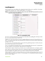
3.3.5. Rover
In this tab, the user can configure a receiver as a rover station.
Figure 3-24. Rover tab
DGPS Parameters
Corrections usage
• Source of DGPS Corrections - serves to specify the source (port) from which the receiver will use
differential corrections for position computation:
• Best - If the Best radio button is selected, the receiver will use differential corrections that
correspond to the most precise of the obtained position estimates. Best means that the solution
has the least RMS error.
• Nearest - If this radio button is selected, the rover will use differential corrections transmitted by
the nearest reference station.
54
www.javad.com
Operation with Receiver
Configuring the Receiver
Rover
• Any -The rover will use all available differential corrections.
• User - If this radio button is selected, the rover will use differential corrections from the user
defined source
• In the Maximum age of DGPS Corrections edit box, the user can set the maximum age (in
seconds) of the code differential corrections used for position computation. It must be an integer
value between 1 and 1200. The default is 30. If the age of the corrections exceeds the value
specified in this edit box, the rover will compute a stand-alone position.
• Use the Maximum age of Iono Corrections edit box to specify the maximum age (in seconds) of
the ionosphere corrections used for position computation.
If you set the Ionosphere-free DGPS Corrections checkbox to on, the rover receiver will use in
position computation both the ionosphere corrections from RTCM message type 15 and differential corrections from RTCM message types 1 and 31 (or 9 and 34).
RTK Parameters
The RTK position Computation Mode drop-down list box serves to toggle between the extrapolation and
delay modes. If Extrapolation is selected, the rover will extrapolate the base station's carrier phase
measurements when computing the rover's current RTK position. If Delay is selected, the rover will not
extrapolate the base station's carrier phase measurements to compute the current rover position. Instead,
the RTK engine will compute either a delayed RTK position (for the epoch to which the newly received
RTCM/CMR message corresponds) or the current stand-alone position (while waiting for new RTCM/
CMR messages coming from the base).
Figure 3-25. RTK Parameters
The Confidence Level for Ambiguity Fixing list box governs the process of the RTK engine fixing integer
ambiguities. The RTK engine uses the ambiguity fix indicator when making a decision whether to fix
ambiguities or not. Low, Medium and High correspond to the indicator's 95%, 99.5% and 99.9% states,
respectively. The higher the specified confidence level, the longer the integer ambiguity search time. This
is the price one pays for the higher reliability of the ambiguity fixed solution.
The Use Measurements for RTK list boxes allow the user to select measurement types used by the rover
for position computation.
www.javad.com
55
Operation with Receiver
Configuring the Receiver
Rover
In the Update Interval od RTK Preference list box the user can set the differential correction update
interval. It should be noted here that for a proper rover setup in RTK Delay mode the user should know
the exact rate at which the reference station broadcasts its differential correction data.
Note: The receiver will use the Base Corrections period control only if it runs in Delay mode. Also, this edit box
is used to provide more reliable synchronization between the base station and rover.
RTK Heading Parameters
This field is used for setting up the heading parameters.
The Heading Mode drop-down list box serves to toggle between the extrapolation and delay modes. If
Extrapolation is selected, the rover will extrapolate the base station's carrier phase measurements when
computing the rover's current RTK position. If Delay is selected, the rover will not extrapolate the base
station's carrier phase measurements to compute the current rover position.
Figure 3-26. RTK Heading Parameters
The Use Fixed Baseline Length drop-down list box to toggle between the sets of carrier phase differential
data received from the reference station:
• last – RTK engine will process the last set of carrier phase differential data received from the
reference station.
• every – RTK engine will attempt to process all sets of carrier phase differential data sequentially
received from the reference station.
Attitude Parameters
This field is used for setting up the attitude parameters: mode, pitch, roll, heading offset, etc.
Figure 3-27. Attitude Parameters
56
www.javad.com
Operation with Receiver
Configuring the Receiver
Ports
3.3.6. Ports
The Ports tab, as shown in Figure 3-28, comprises different sections that are reached via the subtabs:
Figure 3-28. Ports tab
• Serial – Used to specify the data the receiver serial ports will transmit/receive. See “Serial” on
page 57.
• USB – Used to specify the data the receiver USB port will transmit/receive. See “USB” on page
59.
• Bluetooth - Used to specify the data the receiver Bluetooth port will transmit/receive. See
“Bluetooth” on page 59.
• TCP – Used to specify the data the receiver will transmit/receive over TCP/IP network. See
“TCP” on page 60.
• TCPO – Used for transferring corrections to unlimited number of clients.
• CAN – Used to specify the parameters of the CAN port(s). See “CAN” on page 61.
Serial
Use this subtab to adjust the settings for serial ports A, B, C and D (Figure 3-28).
The Input Mode list box allows the user to specify what type of data to input on the selected port.
• cmd- command mode. Being in this mode, the receiver's port recognizes GREIS commands sent
by the user.
• echo - echo mode.
• jps- GREIS input mode. In this mode receiver is capable to recognize both standard and nonstandard GREIS messages.
• rtcm - RTCM 2.x input mode.
www.javad.com
57
Operation with Receiver
Configuring the Receiver
Ports
• rtcm3 - RTCM 3.x input mode. In this mode the receiver recognizes and decodes the RTCM 3.x
messages received through the corresponding port.
• cmr - CMR/CMR+ input mode. For more information on CMR format, please refer to ftp://
ftp.trimble.com/pub/survey/cmr.
• omni - unsupported.
• none - means that the port will ignore any incoming data.
• dtp - the port is currently attached to the Data Transfer Protocol (DTP), so all the input goes there.
This mode could be set only by the get GREIS command. The mode will return to cmd as soon as
DTP terminates.
• term - the PPP data link is currently established over this port, so all the input goes there. This
mode could be set only implicitly by the PPP stack. When parameter is implicitly set to this mode,
attempts to change the mode will fail.
The Output list box allows the user to specify what type of data to output on the selected port.
•
•
•
•
•
•
•
•
•
•
•
•
•
•
•
None – The port outputs nothing.
DGPS RTCM {1,31,3} – The port outputs RTCM message types 1, 31,3.
DGPS RTCM {9,34,3} – The port outputs RTCM message types 9, 34, and 3.
RTK RTCM {18,19,22,3} – The port outputs RTCM message types 18, 19, 22, and 3.
RTK RTCM {20,21,22,3}– The port outputs RTCM message types 20, 21, 22, and 3.
RTK RTCM {20,21,22,23,24}– The port outputs RTCM message types 20, 21,22, 23, 24.
RTK RTCM3 GD min – The port outputs RTCM 3.0 message types GD min.
RTK RTCM3 GD full – The port outputs RTCM 3.0 message types GD full.
RTK RTCM3 GGD min – The port outputs RTCM 3.0 message types GGD min.
RTK RTCM3 GGD full – The port outputs RTCM 3.0 message types GGD full.
RTK CMR {10,0,1} – The port outputs CMR message types 10, 0, 1.
RTK CMR+ {10,0,9} – The port outputs CMR+ message types 10, 0, 9.
RTK JPS min – The port outputs JPS messages.
RTK JPS max – The port outputs JPS messages.
User Defined – The port outputs data specified by the user. It means that the user defined an
arbitrary message set that will be outputted through the port.
In the Period edit box, the user sets the message output interval (in seconds).
Note: It is worth noting, however, that the period of RTCM messages types 22, 3 and CMR message type 1
cannot be changed with this edit box. The default period for the mentioned messages is 10 seconds. If the
user wants to change the period, he/she should use the em command from the Manual Mode window. For
more details on em refer to the GREIS Reference Manual.
To set the baud rate for the corresponding receiver port, use the Baud rate list box.
The checkbox RTS/CTS enables/disables hardware handshaking for the port.
58
www.javad.com
Operation with Receiver
Configuring the Receiver
Ports
USB
This subtab contains settings that allow the user to specify what type of data to input/output on the USB
port (Figure 3-29). These settings are the same as those in the Serial subtab.
Figure 3-29. USB tab
Bluetooth
This subtab contains settings that allow the user to specify what type of data to input/output on the
Bluetooth port (Figure 3-30). These settings are the same as those in the Serial subtab. For more
information, refer to “Serial” on page 57.
Figure 3-30. Bluetooth tab
Additionally here can be checked and/or specified hardware settings such as Bluetooth FCC ID, IC,
Bluetooth mode (on/off), Bluetooth name, and PIN code.
www.javad.com
59
Operation with Receiver
Configuring the Receiver
Ports
TCP
Note: The settings on this subtab are only available if a connected receiver has the Ethernet capability.
With this subtab, the user specifies what type of data to input/output over the corresponding TCP/IP
stream (Figure 3-31). These settings are the same as those in the Serial subtab. For more information,
refer to “Serial” on page 57.
Figure 3-31. TCP tab
TCPO
Note: The settings on this subtab are only available if a connected receiver has the Ethernet capability.
Figure 3-32. TCPO tab
With this subtab, the user specifies what type of data to input/output over the corresponding TCPO port.
These settings are the same as those in the Serial subtab. For more information, refer to “Serial” on page 57.
60
www.javad.com
Operation with Receiver
Configuring the Receiver
Networking Tab
CAN
Note: The settings on this subtab are only available if a connected receiver has the CAN port(s).
With this subtab, the user specifies what type of data to input over the corresponding CAN port (Figure 333). These settings are the same as those in the Serial subtab. For more information, refer to “Serial” on
page 57.
Figure 3-33. CAN tab
3.3.7. Networking Tab
This tab is used to review and configure the networking parameters.
Figure 3-34. Networking
www.javad.com
61
Operation with Receiver
Configuring the Receiver
Networking Tab
LAN
A local area network (LAN) supplies networking capability to a group of computers in close proximity to each
other. A LAN is useful for sharing resources like files, printers, games or other applications. This tab allows the
user ti set up the LAN parameters (Figure 3-34): Receiver IP address, gateway, network mask, MAC Address, etc.
Note: Contact your system administrator to obtain these values.
WLAN
A wireless local area network (WLAN) links two or more devices using some wireless distribution
method (typically spread-spectrum or OFDM radio), and usually providing a connection through an
access point to the wider internet. This gives users the mobility to move around within a local coverage
area and still be connected to the network.
This tab allows the user ti set up the LAN parameters (Figure 3-35):
Figure 3-35. WLAN
Note: Contact your system administrator to obtain these values.
Server
This tab allows the user ti set up the parameters for remote receiver control via TCP/FTP connection.
Figure 3-36. Server subtab
62
www.javad.com
Operation with Receiver
Configuring the Receiver
Networking Tab
Client
The Transmission Control Protocol (TCP) is one of the core protocols of the Internet Protocol Suite. TCP
is one of the two original components of the suite, complementing the Internet Protocol (IP), and
therefore the entire suite is commonly referred to as TCP/IP.
TCP client mode can be configured using this subtab.
Figure 3-37. Client subtab
•
•
•
•
TCP Client Mode - allows the user selecting any of the following mode: NTRIP, RCV, etc.;
TCP Client connection State - shows the connection status;
Timeout - shows TCP connection timeout;
Error - TCP error messages.
PPP
This subtab allows user to set up the Point-to-Point protocol parameters:
Figure 3-38. PPP subtab
The Point-to-Point Protocol, or PPP, is commonly used to establish a direct connection between two
nodes.
Note: Information of PPP parameters is given by Internet service provider.
www.javad.com
63
Operation with Receiver
Configuring the Receiver
Networking Tab
GPRS
This tab allows user to setup all necessary GPRS settings:
Figure 3-39. GPRS subtab
It is necessary to set the dial number, user name and password, access point name and PDP context
identifier to establish a GPRS connection.
Note: This information is given by cell provider.
AT details area is designed for advanced users for finest GPRS tuning. By default, all the settings have the
zero value.
Note: We recommend that you do not send any AT commands to the GSM modem before acquire good
knowledge of the GPRS parameters.
GSM
This subtab is used to review and configure the GSM module parameters:
Figure 3-40. GSM subtab
Mode drop-down list box allows user to select and setup the GSM modem mode:
64
www.javad.com
Operation with Receiver
Configuring the Receiver
Networking Tab
• OFF means GSM modem is inactive. To change modem’s modes user has to set modem’s mode
firstly to OFF and press Apply button, then select and setup the necessary mode from the list. OFF
mode means modem’s hardware reset.
• Slave means registered in GSM network modem is waiting an incoming call to send a data. The
Slave mode is required modem mode for the receiver configured as a base.
• Master means registered in GSM network modem is dialing up and establishing connection with
other modem, using dial number. If the established connection is interrupted, modem dial up and
connect anew. The Master mode is required mode for the receiver configured as a rover.
PIN Code box allows the user to enter the Personal Identification Number (PIN) of its SIM-card.
The Dial number edit box allows the user to set/display a dial number, the phone number of the slave
modem to be dialed in to. The number you can insert is a string comprising up to 14 a/n characters.
Note: Mandatory only when running the GSM modem in master mode.
The Send Time Out edit box allows the user to set/display a time interval of the service word. The transmit
modem will send the service word to the receive modem in every N seconds, where N is a time interval in
seconds from 0 to 255. 0 stands for disabled.
Note: If the receiver has not received any data from the modem for designated seconds, the modem will be
disconnected and then re-initialized.
In the Service Word Repeat Period edit box is possible to set/display a time interval of the service word.
The receive modem will receive the service word from transmit modem in every N seconds, where N is a
time interval in seconds from 0 to 255. 0 stands for disabled.
Note: To ensure reliable and secure modem communication, the Receive Time Out value must be always larger
then the period of transmitting differential corrections. Also, care should be taken that the time interval in
Receive Time Out box is greater than the service word repeat period by 2 to 3 seconds.
UHF
This subtab is used to review and configure the UHF modem parameters (Figure 3-41):
Figure 3-41. UHF subtab
• Modem Mode - Turns on/off UHF modem;
• UHF Modem Frequency - the user can set the necessary frequency;
www.javad.com
65
Operation with Receiver
Configuring the Receiver
Networking Tab
• UHF Protocol Type - allows selecting protocol type:
• Simplex Receiver - This mode is used for JAVAD GNSS internal/external modem on rover side
when the base receiver is equipped with JAVAD GNSS internal/external modem.
• Simplex Transmitter - This mode is used for JAVAD GNSS internal/external modem on base side
when the rover receiver is equipped with JAVAD GNSS internal/external modem.
• Simplex Transmitter to Repeater - means the modem is enabled for transmission data from the
base receiver equipped with JAVAD GNSS internal/external modem to the Repeater.
• Simplex Repeater - JAVAD GNSS internal/external modem enabled as repeater, with no data
being passed to the local communications port.
• TRMB Receiver (only GMSK) - This mode is used for JAVAD GNSS internal/external modem on
rover side when the base receiver is equipped with Trimble internal/external modem.
• TRMB Transmitter (only GMSK) - This mode is used for JAVAD GNSS internal/external modem
on base side when the rover receiver is equipped with Trimble internal/external modem.
• Transparent w/EOT Receiver (only GMSK) - This mode is used for JAVAD GNSS internal/
external modem on rover side when the base receiver is equipped with Pacific Crest PDL modem.
• Transparent w/EOT Transmitter (only GMSK) - This mode is used for JAVAD GNSS internal/
external modem on base side when the rover is equipped with Pacific Crest PDL modem.
• STL Receiver (only 4FSK) - This mode is used for JAVAD GNSS internal/external modem on
base side when the rover receiver is equipped with Satel modem (model SATELLINE-3AS).
• STL Transmitter (only 4FSK) - This mode is used for JAVAD GNSS internal/external modem on
rover side when the base receiver is equipped with Satel modem (model SATELLINE-3AS).
• UHF Modem Output power - This edit box allows the user to set/query the output power value
from 0.03W to 1W.
• Forward Error corrections - allows the receiving modem to correct burst and single bit errors in
the incoming data stream. When enabled, an additional 4 bits per byte of data is transferred over
the RF link. This effectively reduces the data throughput in proportion to the overhead bytes.
Leave FEC enabled unless the data throughput requirements make the overhead unacceptable.
• Scrambling - Enable or disable data scrambling. Select the Scrambling check box if you want data
to be scrambled. Otherwise, keep it clear. For optimal operation of the GMSK modulation, data
should be scrambled. When enabled, the radio modem scrambles and unscrambles the data on
transmission or reception via an exclusive-OR operation with a pseudo-random bit stream. Do not
disable scrambling unless the DTE performs data scrambling and produces a data stream with
approximately the same number of 1's and 0's. Use the Apply button to accept the changes you
have made in the tab.
66
www.javad.com
Operation with Receiver
Configuring the Receiver
Networking Tab
FH
This subtab is used to review and configure the FH modem parameters:
Figure 3-42. FH subtab
www.javad.com
67
Operation with Receiver
Configuring the Receiver
Event Tab
3.3.8. Event Tab
This tab is used to review and configure the 1PPS signal and Event marker settings.
Figure 3-43. Event tab
The Enable PPS Generation list boxes (for PPS a and PPS b) enable the receiver to generate 1PPS signals
and also allows the user to modify the settings related to the selected 1PPS signal.
The PPS Reference Time list box allows the user to select the reference time that the 1PPS signal will be
synchronized with. There are four available reference time scales:
•
•
•
•
GPS means GPS system time.
GLO means GLONASS system time.
UTCus means UTC(USNO).
UTCsu means UTC(SU).
If the user has selected the Tie PPS to its Reference Time, the receiver will synchronize the 1PPS signal
with the chosen reference time. Otherwise, 1PPS will be synchronized either with the receiver's internal
clock or with an external reference frequency applied to the receiver.
The PPS Period edit box determines the rate of generating the 1PPS signals via the corresponding output
connector.
68
www.javad.com
Operation with Receiver
Configuring the Receiver
Advanced
The user can determine millisecond and nanosecond parts of PPS signal offsets with respect to the
selected reference time grid using the Milliseconds of PPS Offset list box for millisecond part and
Nanoseconds of PPS Offset for nanosecond part.
With the Period of Marked PPS Pulses edit box, the user specifies the period of the marked 1PPS signal.
Using the Length of Marked PPS Pulses the user synchronizes the edge (rising or falling) of the 1PPS
signal with the specified reference time.
In order to enable or adjust the event input function, use the controls described below.
In the Synchronize Receiver Clock with... list box, the user specifies that the receiver executes a one-time
synchronization of its one-millisecond cycle grid with the corresponding edge of the event signal.
The Status of Receiver Clock indicator shows whether the receiver clock is actually being synchronized
with the event signals or not. If you see on in the field, it means the synchronization has been done
successfully.
The Rise and Fall values of Event Reference Edge serve to measure the time of either the rising edge or
falling edge of the input event signal.
3.3.9. Advanced
Warning:
Only change these advanced settings when it is known what they mean. Unsuitable changes to these subtabs
can cause the receiver to run improperly. If you are doubtful of any changes you made to these subtabs, click
the Set all parameters to defaults button to get the factory default settings back. For a description of these
subtabs, refer to the corresponding paragraphs below.
Figure 3-44. Advanced tab
www.javad.com
69
Operation with Receiver
Configuring the Receiver
Advanced
Anti-Interference
With the Anti-Interference radio button group (Figure 3-45), the user enables mode allowing the JAVAD
GNSS receivers to suppress the impact of narrow-band interferences.
Figure 3-45. Anti-Interference subtab
The user can assess the presence of interference based on the following information:
• When the number of tracked satellites is fewer (by 2 or greater) than the number of satellites in
view.
• When the signal-to-noise ratio (C/N0) in the C/A channel for the satellites having elevations
above 30 degrees does not exceed 40 dB/Hz.
• When the information about interferences indicates that Jamming Suppressor detected
interference signals within the specified band and also the strength of aggregate in-band
interference is characterized as high or hard. This information you can obtain with the command
em,,jps/JI.
Multipath Reduction
The list boxes CA/L1 Carrier Phase Multipath Reduction and CA/L1 Carrier Multipath Reduction are
used for mitigation of the multipath phenomenon (Figure 3-46).
Figure 3-46. Multipath Reduction subtab
When the reference station and rover station run in DGPS mode and they are not free from the impact of
multipath, we recommend that you select the Code multipath reduction checkbox for both the reference
and rover stations.
Note: If you use a pair of receivers in RTK mode, you can additionally select the checkbox Carrier multipath
reduction for both receivers.
70
www.javad.com
Operation with Receiver
Configuring the Receiver
Advanced
Loop Management
In this subtab the user can configure the settings that deal with the receiver capability of searching,
acquiring and tracking the GPS+ satellite signals (Figure 3-47 on page 71).
Warning: Care should be taken when changing the settings for this subtab. JAVAD GNSS recommends that users do not
change these settings without good reason.
Figure 3-47. Loop Management subtab
The CA/L1 CLL Bandwidth edit box governs the noise bandwidth of the guiding phase lock loops. In this
box, you can enter values between 2 and 50 Hz.
With the CA/L1 CCL Order edit box, the user can toggle guiding and common lock loop order between 2
and 3. Care should be taken when using a 2nd order PLL because this can adversely affect satellite signal
tracking in some cases.
The Strong Loops CCL Bandwidth edit box governs all of the guided loops but the C/A DLLs. Here the
user can enter values between 0.1 Hz and 10 Hz.
The C/A code guided loop bandwidth edit box specifies the bandwidth of the receiver's C/A group delay
lock loop. In this box, one can enter the values between 0.1 Hz and 50 Hz.
With the Enable Adaptive Guided Loops checkbox, the user enables/disables the use of adaptive guided
loops. If the user selects the checkbox, the receiver will adjust the guided loops bandwidths depending on
the actual strengths of the signals tracked. The weaker the signals, the narrower the bandwidths.
With the Enable P/L1 and P/L2 tracking checkbox the user can adjust tracking settings for the receiver. If
one has either a single-frequency receiver or L1 only antenna, it is recommended to disable tracking of
the P/L1 and P/L2 signals.
www.javad.com
71
Operation with Receiver
Configuring the Receiver
Advanced
Note: Enable the Static Mode parameter only if the receiver antenna is completely stationary. If your receiver
antenna may have some movement, even for a few millimeters, disable the Static Mode parameter.
Moving the antenna while in Static Mode may result in a loss of lock to satellites.
The Bandwidth of individual PLL and Bandwidth of common PLL edit boxes mean exactly what their
names imply.
Select the Enable L2 common loop checkbox to avoid the loss of L2 phase tracking in dynamic
applications due to antenna rotation around its axis.
External Frequency
The settings on this subtab, allow the operator to configure the use of reference frequency (Figure 3-48).
It may be either a high-stability external frequency or the receiver’s internal crystal oscillator.
Figure 3-48. External Frequency tab
With the controls in the group, the user specifies the reference frequency input that the receiver will use:
• Internal – means the receiver uses the internal oscillator.
• External – means the receiver uses an external frequency.
Note: By switching from Internal to External and vice versa may result in a temporary loss of lock to satellites.
External Frequency Source Parameters
With the Ext. frequency value edit box the user specifies nominal external frequency value. Here the user
can enter the integer values between 2 and 40 MHz. The default value is 10 MHz.
The Ext. frequency source status field shows whether the external frequency is being used or not:
72
www.javad.com
Operation with Receiver
Configuring the Receiver
Advanced
• off – Indicates that the receiver is using the internal crystal oscillator.
• wait – Indicates that the receiver is waiting for the external frequency lock. More precisely, this
value will be returned in the following three cases:
–If the external frequency oscillator is disconnected
–If the amplitude of input signal is too low
–If the actual external frequency is different from that specified in the Ext. frequency value edit
box
• locked – Indicates that the receiver is using the external frequency.
With the Ext. freq. signal amplitude field the user can estimate the external frequency signal amplitude:
• off – Indicates that the internal oscillator is actually being used.
• low – Indicates that the external frequency signal's amplitude is lower than needed.
• ok – Indicates that the external frequency signal's amplitude meets the specs.
The Oscillator Offset Reduction group box allows the user to govern the behavior of the internal crystal
oscillator.
• The Off radio button means that the oscillator frequency offset reduction mode is turned off.
• The Freq. Locked radio button means that the receiver will adjust the internal oscillator's
frequency until the measured frequency offset is reduced to zero. By using the incoming satellite
signals, the receiver will force the internal oscillator to generate a very stable 20 MHz frequency
signal. This frequency output is available via the corresponding receiver output pin.
Note: The user is able to monitor the offset reduction in the Clock offset field of the GEO tab. After selecting
Freq. Locked the value in Clock offset starts to reduce and soon (usually in a few minutes) it will become
equal to zero, while in contrast Osc. Offset will not change much.
The Freq. and Time Locked radio button means that the receiver will adjust both the internal oscillator's
frequency until the measured frequency offset is reduced to zero and the internal clock until it gets fully
synchronized with the specified reference time scale.
Note: Switching from Freq. Locked or Freq. and Time Locked to Off may result in a temporary loss of lock to
satellites.
Freq. Locked guarantees that the receiver's 20 MHz output will have long-term stability, not necessarily
short-term stability. However, there is a way to assure that both of these characteristics will be good
enough. It can be done by selecting Enable Common tracking on the Loops Management subtab.
www.javad.com
73
Operation with Receiver
Configuring the Receiver
Advanced
Attitude Parameters
This subtab, which is shown in Figure 3-49 on page 74, contains the controls for specifying the multiantenna system parameters:
Figure 3-49. Attitude Parameters tab
74
www.javad.com
Operation with Receiver
Configuring the Receiver
Advanced
Raw Data Management
This subtab, which is shown in Figure 3-50, contains the controls for specifying the frequency at which
the receiver will update raw measurement and position. Also, the user may set up the controls that affect
the signal processing.
Figure 3-50. Raw Data Management tab
The Measurements Update Rate group allows the user to determine the raw data update period. In the
Update Rate edit box, enter a value (in milliseconds) to specify the period. With Effective Measurements
Update Rate, the user can check which period is actually being used by the receiver.
The Position Update Rate group allows the user to determine the receive position update period. In the
Update Rate edit box, enter a value (in milliseconds) to specify the period. With Effective Position
Update Rate, the user can check which period is actually being used by the receiver.
The Pseudorange Smoothing interval edit box specifies the interval over which pseudoranges are
smoothed by using corresponding carrier phase measurements. Here you can enter values between 0 and
900 seconds. Zero designates that carrier phase measurements will not be used for smoothing pseudoranges.
With Ionosphere Correction Smoothing Interval edit box, the user specifies the nominal ionospheric
correction smoothing interval over which raw ionospheric corrections are smoothed (assuming the
receiver has been working for some time and has already obtained enough raw ionospheric corrections to
perform such smoothing). This integer parameter varies between 0…900 seconds. The default value is
60.
With the Minimum Iono Smoothing Interval edit box, the user specifies the minimum smoothing interval
for the receiver to filter raw ionospheric corrections before they can be used in position computation. This
integer parameter ranges between 0 and 900 seconds. The default value is 30 seconds.
www.javad.com
75
Operation with Receiver
Configuring the Receiver
Advanced
In the Doppler Smoothing Bandwidth edit box, the user sets the method used for smoothing Doppler.
There are three available methods:
• Receiver outputs raw (unsmoothed) Doppler. Instantaneous yet rather noisy Doppler
measurements.
• Doppler is computed using two consecutive carrier phase measurements, CarPhase[i] and
CarPhase[i-1], where i stands for the current epoch. Such Doppler measurements are less noisy
than in the first case.
• Doppler is computed using three consecutive carrier phase measurements, CarPhase[i],
CarPhase[i-1] and CarPhase[i-2], where i stands for the current epoch. Doppler measurements
obtained in this mode, are least noisy.
76
www.javad.com
Operation with Receiver
GREIS Commands
Advanced
3.4. GREIS Commands
At the right pane there is a box which allows direct control of the receiver by using GREIS commands. In
manual mode NetHub serves as a terminal communicating with the receiver, (i.e., it allows the user to
send various receiver commands and get responses to these commands). For a complete list of commands
supported by JAVAD GNSS receivers, refer to the GREIS Reference Manual. This document is available
for download from the JAVAD GNSS website (http://www.javad.com/).
Figure 3-51. Manual command entering
Note: We recommend that you do not send any commands to the receiver from the Manual Mode window
before you familiarize yourself with the GREIS Reference Manual and acquire good knowledge of the
receiver parameters.
The size of this field can be changed by stretching out the slider, which separates the parameters and the
field for manual input. The slider has a typical three points in the middle.
At the top of the Manual Mode field there is a command line box in which the user can type a (new)
command line. Alternatively, the user can open the combo-box list and select one of the previously used
command lines. Note that there may be stored up to twenty (20) command lines in the list. Once the
desired command line is typed (or selected), click the Send button or just click the Enter key on your
www.javad.com
77
Operation with Receiver
GREIS Commands
Advanced
keyboard. The receiver's responses will be displayed in the receiver replies window located under the
command line box.
Here, the manual entry of commands is limited, and can be sent set and print commands only, and can
not be shown the output of the message flow. This is due to the fact that the program continues to use the
channel for their needs, for example for downloading a file, or a service base / rover, and while sending
the command is interrupted for a short time to serve this request. Then immediately returns to the
execution of planned operations.
When you enter a command you can use the tip box. Choose the desired item prompted with the arrow
and click on it or press Enter.
Figure 3-52. Tip box
• To cancel the window prompts and enter arbitrary commands, press Esc. In this case, when you
press the Enter, command is sent to the receiver. To call the tips briefly press Ctrl.
• In the input line commands can be replaced with “set” on “print” and vice versa, by pressing the
key combination Ctrl + Space.
• The right of the input command is a button bring up the last commands list.
• Call this window you can also use shortcuts Ctrl + J.
• To write to a file of all sent and received commands, click on the “Start Logging”. The inscription
on the button automatically changes to “Stop Logging”.
• To download the script, click “Load Script”. The program supports a scripting language Tcl.
The program allows you to send commands to the receiver, which has exclusive grip. In this case, the
internal engine of the program does not use this connection, so in this mode, the user can see all the data
sent by the receiver to the port.
78
www.javad.com
Operation with Receiver
GREIS Commands
Load Script Button
Select Manual Mode on the left and click Connect button. Click Disconnect after finish to prevent the
possible problems with receiver management.
3.4.1. Load Script Button
To load script click the Load Script button. Browse the script file location and select the desired file. The
file will be loaded and the script executed. NetHub supports TCL scripts. At the start of the script file
should be the following string: #!/usr/bin/tcl. Without this string the script won’t be recognized as a
script.
Below is the example of the script:
#!/usr/bin/tcl
puts "Checking of baud rate of serial port a. Expected value is 115200"
set result [send "print,/par/dev/ser/a/rated"]
# variable 'result' contains result of operations 'send'
# [lindex $result 0] shows error code. If code is "none" it means no errors.
if {[lindex $result 0] == "none"} {
# Error code is 'none'
# [lindex $result 1] contains answer on command print,/par/dev/ser/a/rated
if {[lindex $result 1] == "115200"} {
puts [concat "Correct baut rate: " [lindex $result 1]]
} else {
puts [concat "Incorrect baut rate: " [lindex $result 1]]
}
} else {
# # Error code is NOT 'none', [lindex $result 1] contains error text
puts [concat "Error while read baud rate. Error code '" [lindex $result 0] "' " [lindex
$result 1]]
}
puts "Script stoped"
www.javad.com
79
900 Rock Avenue, San Jose, CA 95131 USA
Phone: +1(408)770-1770
Fax: +1(408)770-1799
www.javad.com
Copyright © JAVAD GNSS, Inc., 2011
All rights reserved. No unauthorized duplication.