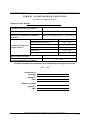
1
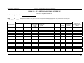
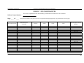
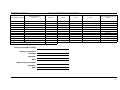
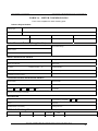
INSTALLATION MANUAL AND DETAILED HARDWARE SPECIFICATION FOR ELECTRICAL SUB-METERING RETROFIT PROJECTS REVISION V3 DECEMBER 2014 DEPARTMENT OF DEFENCE ELECTRICAL SUB-METERING SPECIFICATION AND INSTALLATION MANUAL DOCUMENT STATUS Version No. Issue Date Amendment Details 1 October 2010 Draft version issued for comment 2 June 2012 Draft version issued for comment 2.1 July 2012 Revised draft version issued for comment 2.2 August 2012 Revised draft version issued for comment 2.3 March 2013 Final Draft 3 December 2014 MWH Revision; change of contact details, inclusion of Select Solutions as MDA, substitute of Form 2A, minor text changes Amended by Kris Robinson (Energetics) Ross McLennan (Energetics) Ross McLennan (Energetics) Ross McLennan (Energetics) Ross McLennan (Energetics) Daniel Brooke (MWH) Sub-meter Installation Manual for Retrofit Projects version 3 (December 2014) 2 DEPARTMENT OF DEFENCE ELECTRICAL SUB-METERING SPECIFICATION AND INSTALLATION MANUAL TABLE OF CONTENTS PRELIMINARIES ................................................................................................................................ 6 1. INTRODUCTION................................................................................................................................. 6 2. COVERING NOTE...................................................................... ERROR! BOOKMARK NOT DEFINED. SECTION 1 - OVERVIEW .................................................................................................................. 7 1. EQUIPMENT SUPPLY ......................................................................................................................... 7 2. WORKPLACE HEALTH AND SAFETY (WHS) .................................................................................... 7 3. ROLES AND RESPONSIBILITIES ......................................................................................................... 9 4. SCOPE OF WORKS ........................................................................................................................... 11 SECTION 2 – PHASE 1: PRELIMINARY ASSESSMENT ........................................................... 13 1. GENERAL SAFETY........................................................................................................................... 13 2. DETAILED SCOPING ASSESSMENTS................................................................................................. 14 3. FINALISE HARDWARE SELECTIONS ACCORDING TO THE SPECIFICATION ....................................... 14 4. APPROVAL OF SCOPING ASSESSMENTS AND HARDWARE SELECTIONS........................................... 14 SECTION 3 – PHASE 2: PLANNING AND APPROVAL ............................................................. 15 1. INSTALLATION TIMING SCHEDULE ................................................................................................. 15 2. PROCURE REQUIRED HARDWARE FROM SUPPLIERS ....................................................................... 15 SECTION 4 – PHASE 3 INSTALLATIONS.................................................................................... 16 1. CURRENT TRANSFORMERS ............................................................................................................. 16 2. METER VOLTAGE CONNECTION...................................................................................................... 17 3. METER MOUNTING PANEL AND METER TEST BLOCKS .................................................................... 18 4. METER, MODEM AND AERIAL ......................................................................................................... 18 SECTION 5 – PHASE 4: COMMISSIONING & SIGN OFF......................................................... 20 1. POWER UP ....................................................................................................................................... 20 2. LCD DISPLAY VERIFICATION ......................................................................................................... 20 3. REMOTE COMMISSIONING AND VERIFICATION............................................................................... 21 4. SAFETY .................................................................................... ERROR! BOOKMARK NOT DEFINED. 5. LABELLING ..................................................................................................................................... 22 6. AS-INSTALLED DOCUMENTATION .................................................................................................. 22 APPENDIX A –HARDWARE SPECIFICATION........................................................................... 24 APPENDIX B –STANDARDS AND LEGISLATION..................................................................... 25 1. STANDARDS AND CODES ................................................................................................................ 25 2. RELEVANT STATE BASED AGENCIES .............................................................................................. 26 APPENDIX C –FORMS ..................................................................................................................... 27 FORM 1A – DETAILED METERING SCOPE............................................................................... 28 FORM 1B – SUB-METER HARDWARE SCHEDULE ................................................................. 30 FORM 1C – SIM CARD TRANSFER .............................................................................................. 32 FORM 2A – METER COMMISSIONING....................................................................................... 34 FORM 2B – AS INSTALLED DOCUMENTATION ...................................................................... 37 Sub-meter Installation Manual for Retrofit Projects version 3 (December 2014) 3 DEPARTMENT OF DEFENCE ELECTRICAL SUB-METERING SPECIFICATION AND INSTALLATION MANUAL GLOSSARY OF TERMS AND ABBREVIATIONS AS Australian Standard BCA Building Code of Australia BMS Building Management System CB Circuit Breaker CT Current Transformer DB Distribution Board DEEERMS Defence Directorate of Energy Efficiency, Environmental Resource Management & Sustainability Commonwealth Department of Defence Detailed metering schedule EEGO Detailed instructions on appropriate sub-metering points at an existing Defence site, as previously scoped up by the Defence Representative. Energy Efficiency in Government Operations (Policy 2006, second edition 2007) EMC Electromagnetic Compatibility EMOS Estate Maintenance and Operation Services ESAA Energy Supply Association Australia GPRS General Packet Radio Service GSM Global Systems for Mobile Communications HRC High Rupture Capacity (fuse, usually filled with sand or similar) HVAC Heating, Ventilating and Air-Conditioning IP Internet Protocol LCD Liquid Crystal Display LED Light Emitting Diode LVCT Low Voltage Current Transformer MDA Meter Data Agent MSB Main Switch Board MSSB Mechanical Services Switch Board MTB Meter Test Block NCC National Construction Code NMI National Meter Identifier NSP National Sub-meter Program NZS New Zealand Standard RESO Regional Energy/Environmental and Sustainability Manager Sub-meter Installation Manual for Retrofit Projects version 3 (December 2014) 4 DEPARTMENT OF DEFENCE ELECTRICAL SUB-METERING SPECIFICATION AND INSTALLATION MANUAL RMR Remote Meter Read SIM Subscriber Identity Module TWS Transformer Winding Services VT Voltage Transformer WHS Work Health and Safety Sub-meter Installation Manual for Retrofit Projects version 3 (December 2014) 5 DEPARTMENT OF DEFENCE ELECTRICAL SUB-METERING SPECIFICATION AND INSTALLATION MANUAL PRELIMINARIES 1. Introduction The purpose of this manual is to provide information and guidance on the installation of sub-metering into existing Defence facilities and the installation and connection of radio telemetry devices. Whilst this manual contains material relevant to the electricity industry legislation, Codes of Practice and Standards, it is not intended to provide legal advice on how contractors can meet their own statutory obligations or comply with Legislation, Codes of Practice or industry Standards such as the SAA Wiring Rules AS/NZS 3000. This document provides guidelines for the installation and connection of three phase energy meters and associated wireless telemetry. Where departures from these guidelines may be necessary, prior consultation with Department of Defence will be required. Please direct all questions to the Defence National Sub-meter Program (NSP) representative at [email protected] . Note: If there is any inconsistency between these guidelines and the relevant State, Territory or Commonwealth legislation, then the hierarchy shall be that the requirements of the relevant legislation shall prevail in the first instance. Sub-meter Installation Manual for Retrofit Projects version 3 (December 2014) 6 DEPARTMENT OF DEFENCE ELECTRICAL SUB-METERING SPECIFICATION AND INSTALLATION MANUAL 2. SECTION 1 - OVERVIEW 1. Equipment supply Defence no longer centrally procures sub-meter program hardware (apart from Telstra SIM cards for remote wireless communications). Each sub-meter installation project must provide for hardware procurement in the project scope and budget. It is recommended to request itemised pricing from tenderers to ensure prices being charged for hardware by contractors is appropriate. All hardware procurement, specifically electrical meter and current transformer (CT) procurement, must comply with the minimum hardware requirements as detailed in Appendix A (‘the Specification’). Any deviation from the Specification will result in meter installations that do not provide accessible data, are unable to be used for energy management and will not meet Defence’s strategic energy management objectives. Guidance can and should be sought from the Defence Representative at any time to assist with assessing specific project details including hardware procurement and contractor pricing arrangements, particularly when selecting appropriate hardware for new sub-meter installations. 2. Workplace Health and Safety (WHS) Switchboard Alterations Switchboard alterations shall be carried out by a reputable switchboard manufacturer holding type test certificates from a NATA accredited testing facility for switchboards that they have manufactured and tested. The fault-withstand currents and durations for the certificates held shall exceed the levels and durations required for these works. The manufacturer shall prepare shop drawings for the benefit of planning the works and for future records. The electrical characteristics of the original switchboard shall not be compromised. Refer to the original nameplate attached to the assembly or to operating and maintenance manuals or records held by the manufacturer or in the absence of other information determine from examination of the existing switchboard. Characteristics considered shall include: Enclosure and degree of protection Temperature rise Protection against electric shock Short circuit withstand strength Internal separation of assemblies Dimensions and ratings of bars and conductors Latent Conditions Prior to commencing the works, advise the Project Officer of any associated works which must be done to satisfy Commonwealth, State and Territory regulations but have not been documented. Sub-meter Installation Manual for Retrofit Projects version 3 (December 2014) 7 DEPARTMENT OF DEFENCE ELECTRICAL SUB-METERING SPECIFICATION AND INSTALLATION MANUAL Commissioning Prior to energising, inspect and test the installation in accordance with AS/NZS 3000 and record the results. For any switchboard alterations affecting the original construction of a switchboard, provide certification from the switchboard manufacturer carrying out the modifications that the modifications have been done in accordance with AS 3439.1 to meet or exceed the performance of the switchboard prior to the works. Test and verify the alterations as a partially type tested assembly (PTTA) in accordance with AS 3439.1 on completion of the works. Complete and submit the required notifications to the inspecting authority. Provide a copy of all notifications to the Inspecting Authority (Regulator), the test results and the commissioning records. Update the existing operating and maintenance manuals with these records, information recommended in AS 3439.1 and information which is required for ongoing maintenance and operation. Include the shop drawings prepared for the alterations. Provide one hard copy and one pdf format data file for this purpose. Commonwealth WHS Act, Regulations and Codes of Practice All design and installation work must comply with the Commonwealth WHS Act and Regulations. Reference shall be made to the relevant Codes of Practice published by Safe Work Australia and current at the time of the work. Recommended guidelines and procedures of the codes of practice shall be implemented. Relevant codes of practice for these works include but are not limited to the following: How to Manage Work Health and Safety Risks Safe Design of Structures Managing Electrical Risks in the Workplace Construction Work Work shall only be carried out on de-energised electrical equipment. Regardless of this, safe work method statements shall be prepared for all work and shall include methods for: Verification of de-energised equipment Securing the isolation Altering the isolation for testing, fault finding and re-energising Restoring power Leaving unfinished work Sub-meter Installation Manual for Retrofit Projects version 3 (December 2014) 8 DEPARTMENT OF DEFENCE ELECTRICAL SUB-METERING SPECIFICATION AND INSTALLATION MANUAL 3. Roles and responsibilities Regional Contact The Regional Contact shall be the primary Defence staffer to manage the sub-meter installation project and will typically be the RESO or equivalent. The Regional Contact shall be in control of the project and all other parties as listed below will report to the Regional Contact throughout the project. The Regional Contact is the central point of contact to direct and administer the project; all correspondence shall be directed through the Regional Contact. The Regional Contact shall provide guidance and advice to the Contractor to allow successful assessment and scoping of sub-meter installations in accordance with the NSP objectives and communicate effectively with the Defence Representative to ensure compliance with Defence policies and directives. If no Detailed Metering Schedule (see Defence Representative below) for the site is available, a new scoping exercise must be completed by the Regional Contact. The Regional Contact shall scope up potential sub-metering locations in consultation with the Defence Representative and the Authoritative Defence Contact, as per the guidelines outlined in the ‘Defence Sub-meter Manual for New Constructions’. Installation Contractor The Installation Contractor (referred to henceforth as ‘the Contractor’) is the company contracted by Defence to proceed with the sub-meter installation project. The Contractor shall be a licensed electrical contractor. The Contractor shall have appropriate experience with sub-meter retrofit projects and electrical meter installations. The Contractor shall retain the services of a qualified electrical designer and switchboard manufacturer where required by the retrofit project to meet appropriate State and National standards. The Contractor shall conduct preliminary site assessments to scope installations, negotiate an installation schedule with the Site Contact, procure required project hardware from suppliers and undertake all technical aspects of the sub-meter installation activity including engaging with the Meter Data Agent (MDA) (currently Select Solutions) to ensure reliable communications can be established with sub-meters. The Contractor shall submit all required ‘as installed’ documentation to the Regional Contact so that installations can be signed off and completed. Defence Representative Daniel Brooke Defence Contractor Environment and Engineering Branch National Sub-metering Program (NSP) 0448575625 [email protected] The Defence Representative is the central point of contact for any questions or queries around the sub-meter program and is responsible for sub-meter strategy, hardware procurement advice and Sub-meter Installation Manual for Retrofit Projects version 3 (December 2014) 9 DEPARTMENT OF DEFENCE ELECTRICAL SUB-METERING SPECIFICATION AND INSTALLATION MANUAL consultation, installation sign-off and expert assistance and advice to Defence in all aspects of the sub-meter program. The Defence Representative, with Defence approval, can also provide Detailed Metering Schedules for selected large Defence sites that have already been scoped up for sub-meter installations. These Detailed Metering Schedules outline sub-metering locations and loads previously identified as part of a NSP scoping exercise conducted in 2007. Authoritative Defence Contact (DEEERMS) Allan O’Connor A/Assistant Director - Development & Implementation Directorate of Energy Efficiency, Environmental Resource Management & Sustainability Environment & Engineering Branch Ph: 02 6266 8209 | Fax: 02 6266 8077 BP26-2-B067 | 26 Brindabella Circuit | Canberra ACT 2600 Email: [email protected] The Authoritative Defence Contact within DEEERMS is responsible for overseeing and approving the activities of the Defence Representative and assuring Defence achieves value for money in all submeter program activities. Meter Data Agent (MDA) This role will be performed by Select Solutions. Select Solutions will control the server/software that communicates with each meter, undertake sub-meter remote commissioning, verify correct and full meter function after installation, manage the meter configuration and provide daily sub-meter interval data to Defence managed reporting systems. Site (Base) Contact The Site Contact will be nominated by the Regional Contact and will typically be the regional EMOS contractor or equivalent. The Site Contact will provide site access and any relevant material (e.g. electrical single line diagrams) stored on site. The Site Contact will co-ordinate the installation schedule with base occupants affected by the installation work, power interruptions etc. The Site Contact shall also ensure shutdown of power to carry out any installation work. The Site Contact shall keep the Regional Contact fully informed of all actions taken during the project, including what access and materials have been granted to the Installation Contractor. Hardware Suppliers The hardware suppliers are responsible for supplying meters, modems, SIM card aerials, CTs and meter test blocks to the Contractor on request and also for invoicing the Contractor for these items. The Defence Representative can provide details of potential hardware suppliers for a complying installation when contractors are preparing tender responses, to assist with accurate pricing of projects. Sub-meter Installation Manual for Retrofit Projects version 3 (December 2014) 10 DEPARTMENT OF DEFENCE ELECTRICAL SUB-METERING SPECIFICATION AND INSTALLATION MANUAL 4. Scope of works A detailed description for the scope of works is provided in later sections. In summary, the Submetering work for a particular project, site or base is to proceed in four stages: Phase 1 - Preliminary assessments a. The Contractor, in consultation with the Regional Contact, shall conduct meter scoping to identify preferred metering locations, any variations from the Detailed Metering Schedule provided by the Defence Representative and specific hardware and equipment needs (quantities of hardware, CT type, fuses or circuit breaker, meter test block, mounting panels etc). b. The Contractor shall summarise the total amount of hardware procurement required to complete the meter installations, noting all hardware must meet the minimum requirements outlined in the ‘Defence Sub-meter Hardware Specification’ document (‘the Specification’) including details for: c. i. Electrical meters conforming to the Specification; ii. CTs conforming to the Specification (total number and also number of sets required); iii. Communications packages (wireless modem, cabling and aerial) conforming to the Specification noting that SIM cards for wireless communications are supplied by Defence; iv. Meter test blocks conforming to the Specification; v. Any housing boxes, metering panels or additional switchboards that need to be constructed; and vi. Other hardware items such as fuses and voltage connections. Further details regarding Phase 1 – Preliminary Assessments can be found in Section 2. Phase 2 - Approval and planning a. On gaining approval for the detailed meter scoping and hardware requirements, the Contractor shall negotiate an installation timing schedule with the Site Contact and Regional Contact that takes into account any required power interruptions.. b. The Contractor shall provide detailed pricing for meter installations to the Site Contact and Regional Contact, which includes all required hardware procurement and labour costs. c. On approval of the detailed pricing schedule, the Contractor shall procure the required hardware from the relevant suppliers and shall be responsible for handling and storage of hardware until installations are complete d. SIM cards are ordered directly from the Defence Representative at no cost to the Contractor. e. Further details regarding Phase 2 – Approval and Planning can be found in Section 3. Sub-meter Installation Manual for Retrofit Projects version 3 (December 2014) 11 DEPARTMENT OF DEFENCE ELECTRICAL SUB-METERING SPECIFICATION AND INSTALLATION MANUAL Phase 3 - Installation The Contractor shall: a. Begin the installation of sub-meter system in line with the approved timing schedule and Site Contact access requirements. b. Be responsible for the correct configuration of the meters and associated communications, in collaboration with the MDA and the Defence Representative. c. Conduct progress meetings every two weeks with the Regional Contact. d. Further details regarding Phase 3 – Installation can be found in Section 4. Phase 4 - Commissioning and sign off The Contractor shall: a. Verify correct and full meter functioning from the local meter display. b. Phone the MDA at time of installation to confirm that remote communications are working and the MDA can “see” the meter to allow the commissioning of meter communications. c. Complete commissioning forms for each installed sub-meter installed and provide a copy to the Defence Representative and Regional Contact. d. At the completion of the sub-meter installations, provide as-installed documentation to the Regional Contact for sign off. e. Further details regarding Phase 4 – Commissioning and sign off can be found in Section 5. Sub-meter Installation Manual for Retrofit Projects version 3 (December 2014) 12 DEPARTMENT OF DEFENCE ELECTRICAL SUB-METERING SPECIFICATION AND INSTALLATION MANUAL SECTION 2 – PHASE 1: PRELIMINARY ASSESSMENT 1. General safety The Contractor shall observe regulations for the use of the radio equipment. The following risks associated with using modems for wireless communications at particular locations shall be assessed by the Contractor, with the Regional Contact to be notified of any identified risks. Nearby hazardous and/or explosive devices; Aircraft and other transport vehicles; Petrol/gas stations; Hospitals or any other places where medical equipment is in use; Fuel depots, mining, chemical plants etc; People with personal medical devices, such as hearing aids, pacemakers etc; and Other electronic equipment. Note this list is not exhaustive and only provides general guidance. All relevant laws, regulations and standards must be complied with including, but not limited to, Commonwealth Work Health and Safety legislation. If the Contractor identifies any risk associated with using radio modems for wireless communications, the Contractor shall recommend and implement strategies that mitigate the risk. Alternatively, the Contractor may recommend the removal of the metering point from the scope of works if risks cannot be satisfactorily managed and agreed upon by the Regional Contact, Site Contact and Defence Representative. Any hardware relating to a removed metering point shall be returned to the Defence Representative. The Contractor shall comply with all operating specifications of metering equipment to minimise the risk of equipment malfunction or failure. 2. Utilising existing or planned metering systems In order to meet the requirements of the NSP there may be an opportunity to utilise existing metering systems to provide the required data. The Contractor may: Specify meter hardware and equipment as per the Specification, which will be remotely read by the MDA. These meters will be commissioned and setup for remote reading, with data hosted on a web-accessible database. This process is outlined in Section 3. OR Specify a process for a planned or existing metering system (such as a BMS or district energy management system) to export sub-meter data which will then be hosted on a web-accessible database for Defence use. Please contact the Authoritative Defence Contact for more information on setting up existing or planned monitoring systems to export available sub-meter data for web access. Sub-meter Installation Manual for Retrofit Projects version 3 (December 2014) 13 DEPARTMENT OF DEFENCE ELECTRICAL SUB-METERING SPECIFICATION AND INSTALLATION MANUAL 3. Detailed scoping assessments The Contractor shall perform detailed scoping assessments to finalise: Preferred metering locations; Any variations from the Detailed Metering Schedule provided by the Defence Representative; and Estimated installation hours and specific hardware needs. The provided forms detail the required information for each proposed meter installation location; contact the Defence Representative for assistance with this documentation. The Contractor shall complete Form 1A and submit to the Defence Representative for review. The Defence Representative shall inform the regional contact of all correspondence. 4. Finalise hardware selections according to the Specification The Contractor is required to develop a list of specific hardware requirements which clearly identify the types and quantities of equipment required to successfully complete the project, following the Specification as detailed in Appendix A. The Contractor shall specify if any existing CTs are suitable for re-use. The Contractor shall specify any other hardware required to complete the project such as fuses, wiring, mounting requirements etc required to complete the meter installation and provide these to the Regional Contact to ensure a complete pricing schedule for the project is approved. The Contractor shall complete Form 1B and submit to the Defence Representative for review. The Defence Representative shall inform the regional contact of all correspondence. 5. Approval of scoping assessments and hardware selections Once the required forms have been submitted to the Defence Representative, a review will be carried out to ensure: Value for money for Defence; Compliance with the Specification; and Sign off on any variations from the Detailed Metering Schedule. Any issues with the provided documentation shall be addressed in consultation with the Contractor, Defence Representative, Site Contact and Regional Contact. Sub-meter Installation Manual for Retrofit Projects version 3 (December 2014) 14 DEPARTMENT OF DEFENCE ELECTRICAL SUB-METERING SPECIFICATION AND INSTALLATION MANUAL SECTION 3 – PHASE 2: PLANNING AND APPROVAL On gaining Defence approval for the detailed scoping assessment and hardware requirements from Phase 1, the Contractor shall proceed with Phase 2 to negotiate an installation timing schedule and provide detailed itemised pricing to Defence. Once approved, the Contractor can proceed to order hardware compliant with the Specification detailed in Appendix A, noting that SIM cards are procured centrally through the Defence Representative. 1. Installation timing schedule Once Forms 1A and 1B have been approved by Defence, the Contractor shall liaise with the Site Contact to negotiate a timing schedule which takes into account shutdown of power to specific buildings. This shall allow installations to be grouped together and planned ahead to minimise disruptions to site or base operations and ensure capability is not affected. The Contractor shall allow for hardware supplier delivery lead times in this schedule, which can cause extensive delays in some cases. The Contractor shall contact the Defence Representative with any queries about potential hardware production delays. The Site Contact shall communicate the installation timing schedule to the relevant site or base managers/commanders so that site personnel can plan for any disruptions to services. The Site Contact, Defence Representative and Contractor shall keep the Regional Contact informed throughout this process. The Contractor shall complete a detailed Installation Schedule and submit to the Regional Contact for approval, and provide a copy of the approved Installation Schedule to the Defence Representative. The Contractor shall conduct progress meetings every two weeks with the Site Contact and provide regular updates to the Defence Representative on installation progress. 2. Procure required hardware from suppliers Once the installation timing schedule has been approved by Defence, the Contractor shall procure the approved hardware from the relevant suppliers and organise storage and handling of any delivered hardware prior to installation. Note that the delivery lead time from many suppliers can cause extensive delays in some cases which need to be built into the installation timing schedule as noted above. SIM cards provided by Defence will only be delivered once a responsible person from the Contractor has been nominated and provided assurances for secure storage and management of SIM cards, as per Form 1C. Delivery time for SIM cards provided by the Defence Representative is limited by express post, and can take up to three working days. The Defence Representative shall send the required number of SIM cards to the Contractor and send a copy of Form 1C listing all SIM cards provided in the delivery. The Contractor shall complete Form 1C on receipt of the SIM card delivery, and nominate a responsible person to safely and securely store the SIM cards prior to installation in meters. The Contractor shall complete Form 1C and provide to the Defence Representative for review. Sub-meter Installation Manual for Retrofit Projects version 3 (December 2014) 15 DEPARTMENT OF DEFENCE ELECTRICAL SUB-METERING SPECIFICATION AND INSTALLATION MANUAL SECTION 4 – PHASE 3 INSTALLATIONS A sub-meter installation has four major components: 1 Current transformers; 2 Meter voltage connection; 3 Meter mounting panel and meter test blocks; and 4 Meter, modem and aerial. The “best” location for meters on a supply circuit will be influenced by all of these components. Components one to three can be completed first, followed separately by component four if this reduces the time and/or costs of installation. 1. Current transformers CT types and sizes CT physical dimensions, most critically the diameter of the pass through hole, need to be considered when installing CTs in existing switchboards. It is important that the CT ratio is appropriate for the actual load and is able to cover to the full operating range to ensure accurate measurement e.g. a 250A/5A CT is not appropriate for measuring a 1000A load, or, a 1000A/5A CT is not appropriate for a load that never exceeds 10A. Consideration should also be made for expected future expansion of metered facilities and electrical loads, noting that extended range CTs are available on the market for such situations. Existing CTs If an existing CT meter or ammeter is installed on the circuit to be metered, the existing CTs can be reused if: The CTs appear to be in good physical and electrical condition, based on the assessment of the Contractor; The CTs rated current is suitable for the circuit (based on tong/clamp meter testing by the Contractor); The accuracy class is 1.0 or better (class 0.5 or 0.2); and An electrical test by the Contractor indicates that they are functioning correctly. A new electrical meter is the best test instrument to verify that any in-situ CTs are working correctly. The Contractor shall contact the Defence Representative for any further information required for testing. If any of the CTs are found to be functioning incorrectly, all CTs for the load shall be replaced. If the meter or ammeter connected to the CTs is to remain in service, the new meter can be placed in series with the other equipment so long as the CT burden is not exceeded (consult the manufacturer’s data specifications to clarify the exact requirements). Sub-meter Installation Manual for Retrofit Projects version 3 (December 2014) 16 DEPARTMENT OF DEFENCE ELECTRICAL SUB-METERING SPECIFICATION AND INSTALLATION MANUAL Installation of new CTs Installation of new CTs shall not compromise the original switchboard design. The Contractor shall: Make allowances for fault withstand levels; Take appropriate measures to protect against initiation of arc; Comply with AS3439.1 – Low Voltage Switchgear and Control gear Assemblies; and Comply with AS3000:2007 (2.5.5) – Protection against internal arcing fault currents. CT wiring CT wiring can generally be replaced or extended using double-screw connectors, so long as the total rated CT burden is not exceeded by the addition of the meter and extra wiring. CT wiring is to be 7 stranded copper with a minimum 2.5 mm2 cross sectional area as per the Specification. Detailed information is provided in Table 1 below. Installers shall always short-circuit a CT when the meter is not connected and primary conductor current is flowing. The open circuit voltage can be dangerously high; electrical insulation can break down and the CT core will get hot. This will lead to the premature failure of the CT. When short-circuited, the secondary current substantially cancels the magnetic flux in the core. Table 1: Cabling specifications for common CTs Rated Burden Max Circuit Length 2.5mm2 2.5mm² Max Circuit Length 4mm² Max Route Length 4mm² Max Circuit Length 6mm² Max Route Length Max Route Length 6mm² 5VA 15 metres 7.5 metres 25 metres 12.5 metres 36 metres 18 metres 15VA 45 metres 22.5 metres 80 metres 40 metres - - 2. Meter voltage connection All active voltage conductors are to be coloured according to their phase (red, white or blue). The black meter neutral can be picked up from the neutral link. All wires are to be seven strands 1.5mm2 or 2.5mm2 copper as per the Specification. In general, smart meter and modem packages will be powered by a voltage connection and burden less than 10VA / 50mA per phase. Consult the hardware manufacturer’s data sheets for exact specifications. If circuits are directly connected to the substation bus or main switchboard bus bars, HRC fuses are to be used because the fault currents in a bare-conductor short circuit can be extremely high. Any voltage fuses installed beneath a fixed panel must be safely accessible without the need to disconnect power to the switchboard. Sub-meter Installation Manual for Retrofit Projects version 3 (December 2014) 17 DEPARTMENT OF DEFENCE ELECTRICAL SUB-METERING SPECIFICATION AND INSTALLATION MANUAL 3. Meter mounting panel and meter test blocks The meters historically supplied by Defence are EDMI Mk10, EDMI Mk10E or EDMI Mk6N. These are physically large (18cm wide, 26cm tall) and have a footprint almost as large as an A4 sheet of paper. If the location is awkward or unusual, consult the Site Contact or Defence Representative. Installations are not to intrude into passageways or present any safety hazards. The meter shall not be installed in high security or sensitive areas that will preclude easy access by Defence staff or contractors. Meters shall not be installed in specifically prohibited areas of substations or switchrooms. The meter shall remain accessible to be read, maintained or replaced without the need to disconnect power from the switchboard. This generally means that it is not to be installed behind a fixed panel containing live busbars or exposed lugs. Meter test blocks are to be installed as per the Specification, as this will help with the installation, commissioning and maintenance of the meters by allowing input changes without disturbing the measured load. Kiosk sub stations may require a free-standing meter enclosure. Most radio modems have a maximum operating temperature around 55°C and will fail if left exposed in full sun, similarly most meters have a maximum operating temperature around 70°C. Ensure adequate shading and air circulation for any external installations. The installed meter and modem are to remain clear of strong magnetic fields around heavy bus bars. Magnetic fields can saturate current transformers inside the meter and induce potentials that reduce meter accuracy. The minimum clearance for rated current is shown in Table 2 below. Table 2: Meter and modem minimum clearance for rated current 4. Rated current (amps) Minimum clearance (mm) 150 400 600 1000 1500 2000 3000 4000 100 500 700 900 1200 1400 1700 2000 Meter, modem and aerial Overview The installation steps to connect a standard electrical meter, modem and aerial package are: 1 Mounting of meter and modem (with installed SIM card) in the correct location; 2 Connection of wiring between meter and meter test block; Sub-meter Installation Manual for Retrofit Projects version 3 (December 2014) 18 DEPARTMENT OF DEFENCE ELECTRICAL SUB-METERING SPECIFICATION AND INSTALLATION MANUAL 3 Connection of cabling between meter and modem; 4 Mounting aerial at its nominated location; 5 Connection of aerial to modem; and 6 Removal of meter test block bridging links for CTs. SIM card The SIM card is to be inserted into the modem, generally under a small removable cover ensuring the gold contacts are touching. Take note of the SIM card serial number for the Defence Representative (required for determining the IP address of the SIM card required to establish communications with the meter). Meter terminal block connections Ensure that the manufacturer’s documentation is consulted and followed appropriately when wiring the meter terminal block to the meter test block. Modem connection to meter The radio modem is to be connected to the meter through the appropriate cable port, noting that generally the meter supplies power and data to the modem through this cable. Some pre-fabricated data cables use extremely thin conductors and cannot carry the necessary current to the modem. Ensure quality cabling is used for the installation. Modem and aerial installation location The aerial is to be placed in a location that produces signal strength of at least 40% as indicated by the meter LCD display, but 60% signal strength or more is much preferred (note some meters display signal strength as a decibel reading out of 32 not a percentage). Aerials generally work best when mounted vertically, but this may be affected by local signal reflections. Aerial cables can lose about half of the signal energy every three metres, see the Specification for more information on aerials and associated components. Sub-meter Installation Manual for Retrofit Projects version 3 (December 2014) 19 DEPARTMENT OF DEFENCE ELECTRICAL SUB-METERING SPECIFICATION AND INSTALLATION MANUAL SECTION 5 – PHASE 4: COMMISSIONING & SIGN OFF 1. Power up Perform a visual check of the installation to ensure all components have been properly installed. The meters as described in the Specification will generally arrive pre-configured and should connect to the mobile phone network when power is applied and the modem is connected, however this can vary between manufacturers and suppliers. The meter and modem are generally powered by the voltage connection on the supply. 2. LCD display verification LCD Display An LCD display as prescribed in the Specification should allow the user to scroll through the various meter registers. An example of an LCD pattern is shown in Table 3 below. Not all meters will have the same configuration for the LCD display. Contact the Defence Representative for assistance with the specific LCD configuration for the meter being installed. Table 3: Example of an LCD display pattern Hold “select” (for ~2 seconds) to scroll sets Press “select” to scroll registers below A B C D 1 Act. Tot Power Max Demand Ph A Voltage Signal Strength 2 Act. Power Ph A App. Tot Power Ph B Voltage Current Time 3 Act. Power Ph B - Ph C Voltage Current Date 4 Act. Power Ph C - Ph A Current Display Test 5 - - Ph B Current Frequency 6 - - Ph C Current Current Alarm 7 - - - Latch Alarms 8 - - - Power Supply V 9 - - - Device Config. Verification of LCD Parameters Verify that all elements of the installation are working correctly by viewing the following parameters on the meter LCD display. If any of the following parameters are not available on the LCD display, the Sub-meter Installation Manual for Retrofit Projects version 3 (December 2014) 20 DEPARTMENT OF DEFENCE ELECTRICAL SUB-METERING SPECIFICATION AND INSTALLATION MANUAL Contractor will need to contact the MDA who will be able to perform a remote configuration provided wireless communications can be established. Modem signal strength The modem signal strength is a sample taken at the moment when the modem starts up. Minimum signal strength of at least 40% is required, but signal strength of 60% or more is much preferred. Closing switchboard cabinet doors or the like with the aerial located inside will affect the modem signal strength so ensure cabinet doors are closed as soon as the meter has been powered up and take the signal strength reading after the meter has had time to start up. Modem The modem status is normally shown on the LCD display. The Contractor shall contact the Defence Representative for assistance if required. CT ratio In most cases, the CT ratio will not be pre-set on the meter (basic CT ratio will be pre-programmed to 5/5) until the MDA configures the CT ratio remotely. 3. Remote commissioning and verification The Contractor must contact the MDA to perform the final commissioning and verification (preferably while the Contractor is on site so any adjustments can be made in real time). Select Solutions Meter Transfers Team 03 9238 6495 Hours of Operation: Monday – Friday 7:30am – 5:00pm For escalations and form submission, please email: [email protected] The best way to facilitate this process is to ensure the Contractor advises the MDA, in advance, when the installations will occur to ensure accurate and fast advice is available to the Contractor. The Contractor shall also advise the Regional Contact when commissioning will occur, and the Defence Representative (or the MDA) shall advise the Regional Contact of commissioning outcomes. The following information is required from the Contractor, as a minimum, to perform the remote commissioning and verification (this information can be provided before the installations are complete if known): Meter serial number, meter make and model; SIM serial number (ICCID), Phone Number (MSISDN) or IP address; CT ratio for installed CTs; and Number of phases, voltage per phase, frequency. The remote commissioning will be completed by the MDA which will include any additional meter configuration required such as setting the following parameters in the meter: Sub-meter Installation Manual for Retrofit Projects version 3 (December 2014) 21 DEPARTMENT OF DEFENCE ELECTRICAL SUB-METERING SPECIFICATION AND INSTALLATION MANUAL IP address (corresponding to the SIM card installed in the radio modem); CT ratio; Number of elements/phases; and Frequency. The remote commissioning will ensure the signal strength is satisfactory and that all components have been installed correctly. If any components are not working or have not been installed correctly, it is the responsibility of the Contractor to rectify the problem in consultation with the Defence Representative and MDA to perform the remote commissioning and verification. The Contractor shall contact the Defence Representative (or MDA) to discuss any issues with the remote commissioning process. Once the remote commissioning process has been completed by the Defence Representative, the Contractor shall conduct tong testing on each phase of the metered load to complete Form 2A and submit to the Defence Representative and the Regional Contact as proof of commissioning completion. Once satisfied, the Defence Representative, in consultation with the MDA will sign off the sub-meter installation as completed and ready for online data access. 4. Labelling Permanent Traffolyte type labels shall be used, either screw fixed or glued. Preferably black print on white tape at least 12mm wide. External labelling exposed to the weather shall meet Defence MIEE requirements. 5. Installation Documentation The Contractor shall submit as-installed documentation to the Defence Representative for each project. The required documentation is attached in Appendix C: General Documentation The Contractor shall submit as-installed documentation to the Regional Contact for each site containing the following information: Installer name, business/company and contact details; Site (base) ID and name; Defence Project/Reference Number; Description of site (base) electrical infrastructure; and Summary of work performed. The documentation is also to contain the following information for each sub-meter installation: Sub-meter Installation Manual for Retrofit Projects version 3 (December 2014) 22 DEPARTMENT OF DEFENCE ELECTRICAL SUB-METERING SPECIFICATION AND INSTALLATION MANUAL Meter serial number, modem serial number, SIM serial number and SIM IP address; Substation number/ID associated with each meter; Metered facility ID numbers and names as per Defence Estate Management System (DEMS) or equivalent; Metered facility floor area in m2; Install date and time; Description of CTs (e.g. make/model, size/ratio, solid/split, existing/new etc); Installation location (e.g. pillar number, facility MSB number, etc); Supply description / feeder number / circuit number etc; Number of phases, phase voltages, CT ratios, frequencies; Identification of any equipment stickers or labels used; Commissioning details including date, settings and outcomes as per Form 2A; and Meter make and model. Electrical Single Line Diagrams The Contractor shall produce mark ups of existing electrical diagrams showing the basic electrical reticulation infrastructure for the site or base with clearly identified: Utility meters and NMI meters; Substation numbers and sub feeds; Distribution pillars, MSB, MSSB, DB etc; Facility ID’s; and Sub-meter serial numbers. If no existing electrical diagrams are available the Contractor shall produce new drawings clearly showing (in accordance with Defence requirements): The newly installed equipment in terms of the basic site electrical infrastructure; and The newly installed equipment in terms of the specific building or substation where it is installed, including references to specific circuits or distribution boards; The Contractor shall submit any new drawings produced as part of the retrofit project to the Regional Contact. The Regional Contact shall ensure appropriate filing and storage of this documentation as per Defence requirements. The Contractor shall complete Form 2B and submit to the Regional Contact for review. Sub-meter Installation Manual for Retrofit Projects version 3 (December 2014) 23 DEPARTMENT OF DEFENCE ELECTRICAL SUB-METERING INSTALLATION MANUAL APPENDIX A –HARDWARE SPECIFICATION The generic hardware specification (the Specification) for sub-meter projects is provided as a separate document to this installation manual, please see the sub-metering page of the DRN Environment website or contact the Defence Representative. Sub-meter Installation Manual for Retrofit Projects version 3 (December 2014) 24 DEPARTMENT OF DEFENCE ELECTRICAL SUB-METERING INSTALLATION MANUAL APPENDIX B –STANDARDS AND LEGISLATION 1. Standards and Codes All local and National Electrical and Building Codes (Australian Standards) are applicable and must be adhered to. Network standards are to be considered as a guide as the meters are to be installed on a privately owned network. Australian Standards, Legislation and Defence Guidelines: Commonwealth Work Health and Safety Act, regulations and codes of practice; National Construction Code; Defence Manual of Infrastructure Engineering – Electrical; AS/NZS 3000 – ‘Electrical Installations’ (Wiring Rules); AS/NZS 3439 – Low-voltage switchgear and controlgear assemblies AS/NZS 1939 – ‘Degrees of Protection Provided by Enclosures for Electrical Equipment’; AS/NZS 3147 – Cable Manufacturing; AS/NZS 61000 – ‘Electromagnetic Compatibility (EMC)’; AS/NZS 60044.1-2003 – Current Transformers; AS/NZS 60044.2-2003 – Voltage Transformers; and All relevant State and Territory based legislation as governed by the agencies listed in Table 4. Sub-meter Installation Manual for Retrofit Projects version 3 (December 2014) 25 DEPARTMENT OF DEFENCE 2. ELECTRICAL SUB-METERING INSTALLATION MANUAL Relevant state based agencies Table 4: State and territory agencies governing electrical safety legislation State Agency Contact ACT ACT Planning and Land Authority, Worksafe ACT www.actpla.act.gov.au NSW NSW Fair Trading (Department of Finances and Services) www.fairtrading.nsw.gov.au NT NT Worksafe www.worksafe.nt.gov.au QLD Electrical Safety Office, Department of Justice www.eso.qld.gov.au www.technicalregulator.sa.gov.au SA Office of the Technical Regulator, Office of Consumer and Business Affairs (licensing only) Tas Workplace Standards Tasmania www.wst.tas.gov.au/electricity Vic Energysafe Victoria http://www.esv.vic.gov.au/ WA Department of Commerce www.energysafety.wa.gov.au www.worksafe.act.gov.au/health_safety http://www.environment.nsw.gov.au/ www.ocba.sa.gov.au Sub-meter Installation Manual for Retrofit Projects version 3 (December 2014) 26 DEPARTMENT OF DEFENCE ELECTRICAL SUB-METERING INSTALLATION MANUAL APPENDIX C –FORMS Form 1A - Detailed Metering Scope Form 1B - Sub-meter Hardware Schedule Form 1C – SIM card transfer Form 2A – Meter Commissioning Form 2B - As-Installed Documentation Sub-meter Installation Manual for Retrofit Projects version 3 (December 2014) 27 DEPARTMENT OF DEFENCE ELECTRICAL SUB-METERING INSTALLATION MANUAL FORM 1A – DETAILED METERING SCOPE Form to be completed for each proposed metering point Defence Project Number: Site Name DEMS Site Code For Meter at Site Designator Assigned to Meter Meter Location Physical location meter will be installed Substation Note whether meter will be measuring the total incoming substation power, a substation sub feed or a load downstream from the substation. Floor area of Metered Facilities (m2) ID & Names of Metered Facilities Facility IDs Facility Names List all facilities even if partially sub-metered Application CT Application Cable Busbar S – Type, 200/5 x 3 units CT Size T – Type, 800/5 x 3 units Circle size W – Type, 1500/5 x 3 units Existing CTs To Be Reused? Yes / No Existing CTs To Be Used To Supply Both Existing Meter and New Meter? Yes / No Please note if a specific CT ratio is required outside these generic options Details of Existing CTs Manufacturer Type CT Ratio Rated Burden Current Measurement in Primary Cables/Busbars Red Phase Amps White Phase Amps Blue Phase Amps Sub-meter Installation Manual for Retrofit Projects version 3 (December 2014) 28 DEPARTMENT OF DEFENCE ELECTRICAL SUB-METERING INSTALLATION MANUAL Meter Mounting Point Provide description Distance of Meter From CTs Metres To be measured as cable run distance Is The Distance of Modem From Meter, > 15cm? If Greater Than 15cm, Specify Length Yes / No Metres Max 10 metres Is a High Gain Aerial Required in Place of a Standard Blade Aerial? Yes / No Yes / No Aerial Mounting Point Description Provide Description Evidence provided to the Regional Contact of Contractor’s electrical certifications? Completed by: Company: Qualifications (contractor signing this form must have appropriate electrical qualifications and experience): Signature: Date: Defence Representative: Signature: Date: Sub-meter Installation Manual for Retrofit Projects version 3 (December 2014) 29 DEPARTMENT OF DEFENCE ELECTRICAL SUB-METERING INSTALLATION MANUAL FORM 1B – SUB-METER HARDWARE SCHEDULE Form to be completed for each site Defence Project Number: Page ____ of ____ Add copies of this table on other pages if more room is required and label pages appropriately. Only provided totals on the last page. Electrical Meter Meter Designator Manufacturer Model number GSM Modem/aerial included? (Yes/No) Current Transformer Complies with Specification? (Yes/No) Manufacturer Model CT ratio Complies with Specification? (Yes/No) SIM card to be supplied by Defence? (Yes/No) Sub-meter Installation Manual for Retrofit Projects version 3 (December 2014) 30 DEPARTMENT OF DEFENCE ELECTRICAL SUB-METERING INSTALLATION MANUAL Electrical Meter Meter Designator Manufacturer Model number GSM Modem/aerial included? (Yes/No) Current Transformer Complies with Specification? (Yes/No) Manufacturer Model CT ratio Complies with Specification? (Yes/No) SIM card to be supplied by Defence? (Yes/No) TOTALS *Any instances of non-compliance with the Specification shall be communicated to the Defence Representative Completed by: Company: Signature: Date: Defence Representative: Signature: Date: Sub-meter Installation Manual for Retrofit Projects version 3 (December 2014) 31 DEPARTMENT OF DEFENCE ELECTRICAL SUB-METERING INSTALLATION MANUAL FORM 1C – SIM CARD TRANSFER Form to be completed for each batch delivery of SIM cards from Defence to the Contractor. Defence Project Number: Page ____ of ____ Add copies of this table on other pages if more room is required and label pages appropriately. Only provided totals on the last page. SIM card serial number Responsible person (full name) Company Position Phone Email Secure storage for SIM card available Yes / No Yes / No Yes / No Yes / No Yes / No Yes / No Yes / No Yes / No Yes / No Yes / No Yes / No Yes / No Yes / No Yes / No Yes / No Yes / No Yes / No Yes / No Yes / No Sub-meter Installation Manual for Retrofit Projects version 3 (December 2014) 32 DEPARTMENT OF DEFENCE SIM card serial number ELECTRICAL SUB-METERING INSTALLATION MANUAL Responsible person (full name) Company Position Phone Email Secure storage for SIM card available Yes / No Yes / No Yes / No Yes / No Yes / No Yes / No Yes / No Yes / No Yes / No Yes / No Yes / No TOTAL NUMBER OF SIMS DELIVERED Delivery received on (date): Delivery received by: Company: Signature: Date: Defence Representative: Signature: Date: Sub-meter Installation Manual for Retrofit Projects version 3 (December 2014) 33 DEPARTMENT OF DEFENCE ELECTRICAL SUB-METERING INSTALLATION MANUAL FORM 2A – METER COMMISSIONING Form to be completed for each metering point Defence Project Number: Activity Type Job Comments: Site Name Site ID Install By Installer Contact Number Defence Project Number Record ID Meter Removal Details (if applicable) Make & Model: Removed Readings: Meter Number: CT Ratio: Installed Constant: K= 1. Meter Installation Details Make & Model: Rating: Meter Serial Number: Meter Code: CT Ratio: Installed Constant: K= Installed Reading: Meter Program Configuration ID: Meter Security Passwords ID: Installation Physical Location: Communications Installation Details Modem Make: Modem Model: Modem Serial Number: SIM ICCID or MSISDN: Carrier: Telstra Optus Vodafone Other: _____________ IP Address: Remote Communications Tested By: Declaration Completion Date: Commissioning Completed: Name: Signature: NOMW/NOSW Submitted By: Sealing Pliers No: Yes No CT Details Existing/New Manufacturer Type Class Terminals Connected Connected Ratio Available Ratios . Sub-meter Installation Manual for Retrofit Projects version 3 (December 2014) 34 DEPARTMENT OF DEFENCE Phase Polarity Prim/sec (P1/S1) ELECTRICAL SUB-METERING INSTALLATION MANUAL Serial Numbers Primary Current (3) Rated CT Burden (4) Cable route Length x 2 (M) Secondary Current CT constant confirmation Terminal Volts (mV) Admittance Test (mS) (1) Cal. Burden Z=mV/Isec A B C (2) Rated VA (5) Cable conductor size (mm²) Resistivity (6) Est.Burden /Ph=((4)x(5 ))+ Meter burden (7) Only undertake if “Calculated burden” cannot be completed. Refer Jemena installation procedure for values for items 5&7 Burden OK when Cal.burden (1) is less than or equal to rated burden (3) or Est burden (6) BURDEN OK? Yes / No Burden Values Copper Cable Size 1.5mm 2.5mm 4.0 mm 6.0 mm Burden Ω Per Meter 0.0119 0.0071 0.0045 0.00302 Meter Type L&G (Email/AMPY) EDMI MK 3, 6 & 10 Emermet TML 3005 2P Meter Burden Ω 0.0024 0.003 0.0005 0.004 VT Details Make Serial No. Class Rated VA Available Ratios Connected Ratio Terminals Connected Meter Registration Check Phase Secondary Current Volts Power Factor A x x = B x x = C x x = Watts Time / Watts Calculated (5 pulses) Time / Watts Measured (5 pulses) Comments: . Sub-meter Installation Manual for Retrofit Projects version 3 (December 2014) 35 Percentage Error DEPARTMENT OF DEFENCE ELECTRICAL SUB-METERING INSTALLATION MANUAL Check List Item 1. Customer advised of prior to visit? 2. Readings obtained from existing meter If smart meter, contact existing MDP to read prior to removal YES NO N/A Comment Who was advised: 1) 2) 3) Record all register readings. st Record outgoing MP & MDA on 1 page removed meter details section Return all metering equipment labelled to asset owner. within 7 days of completion of works 3. Has Meter Battery been connected? 4. Phase sequence verified correct 5. Check individual phases for current direction. Check direction of meter arrow indicators 6. CT ratios verified If unable to verify meter constant by measurement or visual inspection, please notate on page 3 note section. 7. Meter constant programmed into meter Yes / No 8. Comparison between primary & meter KW. Should be the same taking constant into account Load needs to be stable. 9. Time & date on meter/time clock is correct Time should be EST - Beware of 12hr or 24hr settings 10. Record mtr program No. Check t/clk operation & program if applicable. 11. All test links shorts removed & links closed. 12. All metering connections tightened & checked 13. All meter voltage leds/indicators on. 14. Meter potential’s fused? Yes/ No N/A CT chamber rating: Panel rating: If N/A explain 15. NMI & MP stickers are applied as applicable. 1) NMI/Constant sticker should be applied to meter panel & details filled in legibly 2) CT sticker to CT cabinet 16. If smart meter installation, contact office test installation. Advise meter details as required Call 03 9238 6495 for communications commissioning 17. All metering equipment sealed 18. Customer taking pulses YES / NO Record pulse taken & values on page 3 note section 19. Return any meter certification documents with installation document Comments: . Sub-meter Installation Manual for Retrofit Projects version 3 (December 2014) 36 DEPARTMENT OF DEFENCE ELECTRICAL SUB-METERING INSTALLATION MANUAL FORM 2B – AS INSTALLED DOCUMENTATION Form to be completed for each site Defence Project Number: Total Meter Installations Completed Total Meter Commissioning Completed Mark Up of Existing Electrical Single Line Drawings or New Single Line Drawings Sketched? Do Electrical Single Line Diagrams Show -> Mark Up of Existing Drawings / New Drawings Electrical Supply Reticulation Yes / No Utility Meters & NMI Numbers Yes / No Substation Numbers & Sub Feeds Yes / No Distribution Pillars, MSB, MSSB, DB etc Yes / No Facility IDs Yes / No Meter Serial Numbers Yes / No Works completed to relevant State/Territory standards? Works completed to Commonwealth/National standards? Yes / No Yes / No Has all As-Installed Documentation been submitted to the Regional Contact? YES / NO Completed by: Company: Signature: Date: Regional Contact: Signature: Date: Sub-meter Installation Manual for Retrofit Projects version 3 (December 2014) 37