1
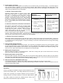
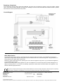
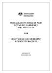
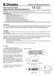
Installation & Operating Instructions
Base Unit Fan Heater
Model: BFH24R, BFH24RB & BFH24RS
08/17337/3 Issue 3 APR ‘05
IMPORTANT: These instructions should be read and carefully retained by the user.
Safety Warnings
•
•
•
•
•
•
•
DO NOT COVER OR OBSTRUCT the air inlet or outlet grille.
ENSURE THE APPLIANCE IS EARTHED.
Do Not place heater immediately below a socket outlet.
If the appliance is covered, there is a risk of fire.
Do not use this heater with young children unattended.
Do not use this heater in areas where excessive dust exists.
Do not touch or obstruct the grille areas when the heater is in operation.
Introduction
This heater has been designed for fitting in the space behind the plinth of floor standing kitchen units or other fitted furniture
units. It is recommended that the heater is not installed under cupboards used for storing perishable goods. It can be
accommodated in plinths with a minimum height of 12Omm, and is suitable for cupboards of 500mm width and above.
Installation
The installation of this appliance should be carried out by a competent electrician and be in accordance with the current IEE
wiring regulations.
Before undertaking installation work, ensure the electricity supply is disconnected from any relevant fixed wiring.
The heater is more easily fitted during the installation of new furniture units, or on existing furniture units if they can be
temporarily moved from their position against the wall. If an existing furniture unit cannot be moved, then it may be
necessary to remove the back of the unit in order to gain access to carry out the wiring installation.
Before installing the unit consider the location with respect to the following;
•
The electrical supply and cable length.
•
Position heater to deliver heat effectively without causing personal discomfort from overheating while standing at
work surfaces etc.
•
Minimum plinth height of 120mm and minimum furniture unit width of 500mm.
Procedure
1. Cutting the aperture in the Plinth
Cut aperture in furniture unit plinth to
This must be
dimensions shown.
positioned so that the minimum distance
from the bottom of the aperture to the TOP
surface of any floor covering is not less
than 12mm and not more than 25mm.
If an overhang above the heater is greater
than 75mm, then a distance of at least
100mm must be maintained between the
overhang and the uppermost part of the
heater.
Note: If fitted in corner with adjacent
cupboards to left hand side of heater then a
distance of at least 150mm must be
maintained between the left hand end of
the heater and the front of the adjacent
cupboard door.
*
This dimension must be maintained
above the top surface of any floor covering
material. All dimensions in millimetres.
2. Power supply connection
Check that the supply voltage details on the heater are in accordance with your electricity supply. A 2.5 metre length of
inter-connecting cable is supplied. The 6 core inter-connecting cable should be routed from the plinth space to the
connection box, ensuring that the cable is left with enough slack to allow removal of the appliance for maintenance. The
cable must be protected from any sharp edges.
a.) Remote Control Switch Panel
Determine desired position for remote control switch
panel above work bench i.e. 900mm minimum above
floor level. It is designed for use with either a surface
mounted or flush mounted box as listed in the Table
opposite. The left hand column of the Table indicates
the type of conduit/trunking required, if any, and the right
hand column indicates the corresponding two gang box
for the control switch panel. Fix the chosen mounting
box in position.
Flush or Surface
Mounting
Conduit/Trunking
Two Gang box for
Remote Control Switch
MK Switches
1.
Embedded – Rounded
or oval conduit
1. MK 892 ALM (Metal)
2.
Surface Mounting minitrunking
3.
Surface Mounting
Cable clipped to wall
b.) Electrical Connection to Remote Control Panel
–
2. Marshall Tufflex MSSB
16 (PVC White)
3. MK 2142 WHI (White
Moulded)
Strip back the outer sheath of the inter-connecting cable
by 125mm, at both ends. The conductor sheath should
be stripped back by 8mm. Select suitable trunking or
4. Marshall Tufflex MDLB
4. DryLining Box
conduit from the Table if required. Connect remote
2 (Plastic)
control switch panel to the six core inter-connecting
cable, in accordance with the wiring diagram.
If the 2.5 metre length of cable supplied is insufficient and a substitute cable is used, Ensure that the conductors are of
minimum 1.5mm² cross-sectional area. The same size of conductor should be used to link the switch and fuse terminals
on the remote control switch panel as indicated in the wiring diagram.
c.) Electrical Connection to Appliance
Remove the screws securing the top, front and rear covers in order to gain access to the terminal block. Feed the 6
core flexible inter-connecting cable through the cable-clamp at the side of the heater and connect it to the terminal block
in accordance with the wiring diagram. It may be necessary to remove the terminal block from its fixing while making
connections to it.
3. Fitting the Rear Support Bracket
The heater is supplied with a rear support bracket. Fit to the back of the appliance with the two screws supplied. Adjust
the rear support bracket so that the vertical distance from the underside of the appliance to bottom of the rear support
bracket equals the vertical distance from the floor in the cupboard space to the bottom of the aperture opening. The
slots in the rear support bracket allow it to be adjusted to the required height.
4. Marking the Fixing Positions
Slide the heater into position in the plinth aperture. Mark the six fixing holes (two on each side and two on the top
Remove the heater and drill 2mm pilot holes.
5. Mounting the Heater into the Plinth
When the cable connection has been made and the rear support bracket adjusted, slide the heater into the aperture
ensuring that it is adequately supported and that the inlet grille is not obstructed. Use the six screws provided to secure
the heater to the plinth. (See point 6 below for stainless steel grill fitting).
6. Stainless Steel Grille (BFH24RS model only).
The stainless steel grille is supplied (in the plastic covering) as an attachment for the front of the heater.
This should be offered up to the front of the heater before fixing the heater to the plinth. Use the six screws to secure it
to the front of the heater / plinth.
Operation
The fan is brought into operation using the switch marked Fan on the
remote control switch panel. The heating elements will not function
until the fan is operating. The switches marked ‘I‘ and ‘II’ control the
heating elements. The switch marked ‘I’ controls the 800W element.
The switch marked ‘II’ controls the 1600W element. When both
switches are ON 2400W heat output is available.
Operation of Thermostat
1. The heater incorporates a variable thermostat which is controlled
by a knob situated on the top right hand side of the front panel.
The knob is marked *, 1 - 6, MAX, representing a temperature
range of 5°C to 30°C. Lowest setting provides frost protection
level.
2. Turn thermostat knob to maximum. When the room has reached
the desired comfort level turn back the knob until the thermostat
just ' clicks ' off. If the knob is left in this position the room
temperature will be maintained automatically at the chosen level.
Remember
If, when the heater is switched on, the room temperature is above that selected on the thermostat knob the heater will not
operate. This is as it should be, and the thermostat is performing its function correctly. Should a higher temperature be
required than the one selected, then it will be necessary to turn the thermostat knob to a higher setting to bring the heater
into operation.
Mains Indicator Neon Lens
Located at the bottom left of the front panel, the ‘mains indicator neon lens’ is to indicate when there is electrical supply to
the heater and comes on when the fan switch, on the remote switch assembly is selected.
Cleaning & User Maintenance
WARNING: DISCONNECT SUPPLY before carrying out maintenance.
General Cleaning
External appearance can be maintained by wiping occasionally with a
damp cloth; for stain removal, a weak soap solution can be applied, then
wipe dry.
Internal Cleaning & Maintenance
To help prevent the build up of dust and fluff in the heater it is advisable to
apply the soft brush attachment of a vacuum cleaner to the grille
occasionally (fig. 1).
From time to time it may be necessary to remove the heater from the
furniture unit so that the interior of the heater and the heater compartment
can be cleared of any accumulated dust or fluff by means of a vacuum
cleaner (fig. 2).
To remove, unscrew the six fixing screws and withdraw the appliance from
the plinth.
To gain access to the inside of the appliance remove the screws securing
the top cover.
Clean the interior of the heater using the soft brush attachment of a
vacuum cleaner, taking care not to damage the fan.
Refit the top cover. The interior compartment of the furniture unit should
also be cleared of dust and fluff using the vacuum cleaner nozzle (fig. 3).
Remount the heater in the plinth ensuring the rear support bracket is still
adjusted correctly. The electricity supply to the heater can now be
switched back on.
Safety – overheat protection
For your safety, this appliance is fitted with a thermal cut-out. In the event that the product overheats, the cut-out switches
the heater off automatically. To bring the heater back into operation, remove the cause of overheating, then turn off the
electrical supply to the heater for a few minutes. When the heater has cooled sufficiently reconnect and switch on the
heater.
If the cut-out operates repeatedly, contact your supplier
Procedure for resetting the cut-out;
A.
B.
C.
Disconnect the electricity supply to the appliance either by switching off at the isolating switch panel.
Determine what has caused the cut-out to operate and rectify.
(Note : This should only be undertaken by competent persons with experience of repairing electrical appliances
and in full knowledge of the possible hazards involved ).
After a short time delay to allow the appliance to cool down, all that is required to return the heater to normal
operation is to switch the electricity supply back on.
Replacing 13amp fuse
The 13amp fuse must be ASTA approved to BS1362. The fuse may be replaced by pulling out the fuse holder, marked
‘fuse’, on the remote switch assembly until the fuse is dislodged. The new fuse should then be located and held in position
while the fuse holder is pushed back into position.
Circuit Diagram
After Sales Service
Your Dimplex base unit fan heater is guaranteed for two years from date of purchase. We undertake to exchange or
repair free of charge within this period any part found to be defective due to a manufacturing fault. This guarantee in no
way prejudices your rights under common law.
Should you require after sales service, please get in touch with the supplier through whom you purchased the appliance,
or your nearest service agent.
Please do not initially return a faulty appliance or part of an appliance to us as this may result in transit damage and / or
delay in providing service. Let us know your difficulty, quoting the model number and series letter of the appliance. We
will then take the appropriate action.
This product complies with the European Safety Standard EN60335-2-30 and the European Standard for Electromagnetic Compatibility
(EMC) EN55014, EN60555-2 and EN60555-3 which cover the essential requirements of EEC Directives 89/336.
Glen Dimplex UK Limited
Millbrook House
Grange Drive
Hedge End
Southampton
Hampshire SO30 2DF
UK customer help line (8.00AM – 6.00PM Mon-Fri; 8.30AM-1.00PM Sat)
Customer Services:
Tel.
Fax.
Republic of Ireland
0870 7270101
0870 7270102
01 8424833
[c] Glen Dimplex UK Limited
All rights reserved. Material contained in this publication may not be reproduced in whole or in part, without prior permission in writing of Glen Dimplex UK Limited.