1
User Manual for the Devil Fish MIDI In and Out
system, with Dynamic Bank/Channel Switching
Robin Whittle 27 September 2014 www.firstpr.com.au/rwi/dfish/
Please see the Devil Fish site for separate manuals for the V1.0.0 to V1.0.3 MIDI In systems and for the
V1.0.4 and later MIDI In system.
The words AND and OR denote the logic functions and and or.
The pages which concern the MIDI Out functionality are:
5
Default behaviour and most important points.
14, 16 & 17
Overall description.
35 to 38
Base MIDI In Channel, Transposition and Filter
Frequency Control Changes.
41
MIDI Sync In and Out.
44
Transmit channel = Receive channel.
45 to 56
Tabular and detailed descriptions of Int Seq mode, Ext
CV mode and MIDI In Follow mode.
The pages which concern the Dynamic Bank and Channel Switching
capabilities are: 58 to 105.
This manual covers four installation options, and for any one Devil
Fish, in the printed and bound version of the manual, some of these
pages will either not be included or will be marked with a cross, since
they are inapplicable to this particular Devil Fish. These page numbers
are listed on page 2.
© Robin Whittle 2004 – 2014. TB-303 is a trademark of the Roland Corporation. TT-303 and Bass Bot are
trademarks of Cyclone Analogic. MS Word to PDF via Bullzip PDF printer: www.bullzip.com
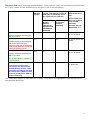
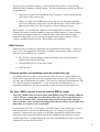
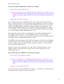
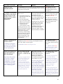
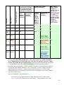
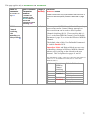
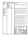
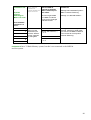
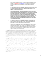
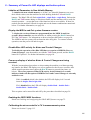
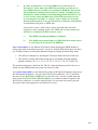
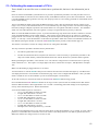
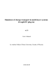
This Devil Fish has the following installed features. Some pages are either not included or are marked with
an X in the printed version manual because they do not refer to this installation.
Installation
3
32 Bank
Memory
system
Two 3.5mm Audio or CV Input
sockets, with detector circuits &
XOR gates to potentially invert
the output bits of 2 switches:
Two switches
for Dynamic
Channel
Switching
No
na
No
68, 69, 70, 71, 72,
73, 74, 78 and 86.
No
na
Yes
67, 72, 73, 74, 77, 84
and 86.
Yes
No
na
68, 69, 70, 71, 72,
73, 74, 78 and 86.
Yes
Yes
na
67, 68, 69, 70, 71,
77, 84 and 85.
marked with an X.
Dynamic Channel Switching via
MIDI In Ch 15/16 AND two
switches, each with an Audio/CV
input socket, detector circuit and
switch bit inverter circuit.
5
Those in pale blue
italics are retained
in the printed
manual for
reference, but are
Two left-most
Memory
Address
switches for
Dynamic Bank
and Channel
Switching
Dynamic Channel Switching via
MIDI In Ch 15/16.
4
Pages which do not
apply to this Devil
Fish
Dynamic Channel Switching via
MIDI In Ch 15/16.
The 32 Bank Memory system is
not part of this.
6
As for 4 above, but the two
switches are the left two of the
32 Bank Memory system. Their
potentially inverted bits are used
for both Dynamic (Memory) Bank
Switching and Dynamic (MIDI In)
Channel Switching.
One of the above table rows and some text on pages 59, 60 and 61 are highlighted in a manner specific to
this particular Devil Fish.
2
Contents
0 - Features, quickstart and what to do with this User Manual................................5
MIDI In capabilities of the MIDI In (only) system............................................................... 5
Additional MIDI In facilities which are part of the MIDI In and Out system ........................ 6
Facilities of the MIDI Out sub-system in the MIDI In and Out system ............................... 7
Quickstart and what to do with this User Manual .............................................................. 9
1 - Overall description................................................................................................12
MIDI In Notes ................................................................................................................. 13
MIDI In Accent................................................................................................................ 13
MIDI In Slide................................................................................................................... 13
MIDI In Gate (Sustain).................................................................................................... 14
MIDI In Filter Frequency ................................................................................................. 14
MIDI In Sync................................................................................................................... 14
MIDI Out Notes............................................................................................................... 14
MIDI Out Velocities for Accented and Non-Accented Notes can be controlled by
MIDI In Control Changes ................................................................................................ 16
No transposition of MIDI Out notes with respect to the pitches played on the
Synthesizer..................................................................................................................... 16
MIDI Out Control Changes for Filter Frequency.............................................................. 16
MIDI Out Sync ................................................................................................................ 17
Firmware updates via installing a new microcontroller chip ............................................ 17
The Sync / MIDI In socket is not an ordinary MIDI In socket........................................... 17
2 - The “Front Panel” .................................................................................................18
Initialising the User Definable Parameters...................................................................... 18
Firmware version display ................................................................................................ 18
Power-on display of whether Notes & Control Changes are being received ................... 19
Blue LED MIDI activity display and how to disable it....................................................... 19
Turning on and off Reception of MIDI Notes and Control Changes ................................ 20
Altering the value of a User Definable Parameter........................................................... 22
3 - User Definable Parameters 0 to 8 ........................................................................25
4 - Interaction between the MIDI In system and the TB-303 / Devil Fish................27
The standard TB-303 ..................................................................................................... 27
Devil Fish CV In.............................................................................................................. 29
Devil Fish Gate............................................................................................................... 30
Devil Fish Slide............................................................................................................... 31
Devil Fish Accent............................................................................................................ 31
MIDI In Sync system....................................................................................................... 32
5 - Details of MIDI In features and User Definable parameters 0 to 8 ....................33
Monophonic reception of multiple notes ......................................................................... 33
The Blue LED ................................................................................................................. 33
Base MIDI In (Receive) Channel (Parameter 0) ............................................................. 35
MIDI In Transposition (Parameters 1 and 2)................................................................... 36
MIDI In and MIDI Out Filter Frequency Controller (Parameter 3).................................... 38
MIDI In Slide on Tied Notes (Parameter 4)..................................................................... 40
MIDI In Sustain-Slide Controller (Parameter 5)............................................................... 40
MIDI In Accent Velocity Threshold (Parameter 6)........................................................... 41
Receive and Transmit MIDI Sync (Parameter 7) ............................................................ 41
Confusion due to Unplug Timer being disabled .............................................................. 43
MIDI Out (Transmit) Channel (Parameter 8).................................................................. 44
3
6 - MIDI Out further explanation ................................................................................45
Tabular description of the 3 MIDI Out modes ................................................................. 45
MIDI In control of Velocity values for MIDI Out notes ..................................................... 48
Int Seq mode.................................................................................................................. 48
Ext CV mode .................................................................................................................. 50
MIDI In Follow mode....................................................................................................... 52
MIDI Out timing and other technical details .................................................................... 54
Slight variations in threshold voltage .............................................................................. 56
7 - Dynamic Bank/Channel Switching (DBCS) .........................................................58
Special Power-Up procedure to enable DBCS MIDI features ......................................... 58
Overview of DBCS.......................................................................................................... 58
Initial explanation of DBCS - Installations 4 and 6 .......................................................... 62
Data flow for Installations 3 and 5................................................................................... 67
Data flow for Installation 4 .............................................................................................. 68
Data flow for Installation 6 .............................................................................................. 72
Enabling and configuring the DBCS MIDI features ......................................................... 75
User Definable Parameters 9 to 11, for Dynamic Bank/Channel Switching .................... 76
MIDI In Channel 15 or 16 Keyset Note Events & Control Changes................................. 80
Dynamic Channel Switching: the Effective MIDI In Channel ........................................... 83
Dynamic Channel Switching: receiving Notes in Immediate or Delayed Mode................ 87
MIDI In Note reception without Dynamic Channel Switching........................................... 88
MIDI In Note reception with Dynamic Channel Switching ............................................... 90
Immediate Mode............................................................................................................. 91
Delayed Mode ................................................................................................................ 93
Transitions between Immediate and Delayed modes ..................................................... 97
Precise timing of DBCS Audio/CV, detector and toggle-switch, signals.......................... 99
8 - Summary of Power-On LED displays and button options...............................106
Initialise all Parameters in Non-Volatile Memory........................................................... 106
Display the MIDI In and Out system firmware version .................................................. 106
Disable Blue LED activity for Notes and Control Changes............................................ 106
Power-on display of whether Notes & Control Changes are being received ................. 106
Enabling the DBCS MIDI functions ............................................................................... 106
Calibrating the microcontroller’s CV In measurement system....................................... 106
9 - Advanced use of the Sync-MIDI-In socket ........................................................107
Isolation of MIDI Pin 2 .................................................................................................. 107
MIDI In whilst still using the internal Tempo Clock and Run/Stop ................................. 107
Receiving MIDI Sync and driving external devices........................................................ 108
10 - The Pesky C4 Note in Pattern Play mode........................................................108
11 - Summary of MIDI In and MIDI Out messages .................................................110
MIDI In Messages received by the Devil Fish ............................................................... 110
MIDI Out Messages generated by the Devil Fish.......................................................... 112
12 - Calibrating the measurement of CV In ............................................................113
13 - Firmware version history..................................................................................114
14 - Document history..............................................................................................114
4
0 - Features, quickstart and what to do with this User Manual
The Devil Fish modified TB-303 can be fitted with a MIDI In system or a MIDI In and Out
system. Here are the most important things you need to know about the MIDI In and Out
system. It does not support:
o Loading or dumping of Pattern or Track data from the battery backed up memory
system.
o MIDI In control of any knob or button functions.
o MIDI Out transmission of the state of any knobs or buttons, except the Run/Stop
button (in the absence of MIDI In Sync reception or an external source of
DIN/Roland Sync) and in Int Seq and Ext CV modes, the Accent button, which
affects the Velocity of MIDI Out notes.
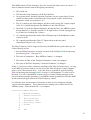
MIDI In capabilities of the MIDI In (only) system
The following features are supported by both the Devil Fish MIDI In (only) system (for
which there is a separate manual) and the MIDI In sub-system of the MIDI In and Out
system:
•
The Devil Fish receives MIDI if you plug a MIDI lead into the Sync Socket.
•
It receives Note and Filter Frequency messages on Channel 1. (This is the default –
the system can receive in any channel 1 to 16, with this and other user-controllable
settings being stored in non-volatile memory.) Middle C is the C on the left of the
TB-303 keyboard in Pattern Write mode when there is no transpose up or down.
There are non-volatile user settings for transposition. (User Definable Parameters 1
and 2, as described on page 36.)
Reception of Notes and Control Changes can be enabled and disabled with the
procedure described on page 20. This state is stored in non-volatile memory so it is
possible that the machine can be turned on with MIDI In reception of Notes and
Control Changes disabled. This is indicated by a distinctive pattern of flashing by
the Blue LED, as described on page 19. If the Devil Fish does not receive any Notes
or Control Changes and you are unable to understand why, perhaps it is because you
previously turned off this reception (not necessarily intentionally), and because this
state is retained in non-volatile memory and so disables this reception when the
machine is turned off and on.
•
Note On events with velocities 1 to 63 will be played without Accent and those with
velocities 64 to 127 will be played with Accent ON. Instructions for selecting
different thresholds are on page 41.
•
The Devil Fish modified TB-303 is a monophonic instrument. If two or more notes
are active from MIDI In, it will play the pitch of the most recent of these notes. As
this and other notes are turned off, the pitch revert to the most recently turned on of
the currently playing notes, for up to a maximum of 8 notes being on at once. (There
is an 8 note deep Note Stack for the MIDI In sub-system of the MIDI In and Out
system, while the MIDI In only system, without MIDI Out, uses a 10 note deep Note
Stack.)
5
•
If one or more MIDI In notes is still active when a new one is played, the new note
will, by default, be played with Slide ON. This can be disabled by setting the value
of User Definable Parameter 4: MIDI In Slide on Tied Notes (see page 40) to 0.
•
By default, Control Change 1 messages (Mod Wheel) control the Filter Frequency,
with an approximately 5 octave range. This source of control adds to, rather than
overrides, all the other internal signals and the Cutoff pot, which also affect the Filter
Frequency. (This Controller number can be altered from the default of 1 with User
Definable Parameter 3, as described on page 38.)
•
A Controller number 1 to 19 can be selected (User Definable Parameter 5, described
on page 40) so that Control Changes values can turn independently turn on Slide and
Sustain (Gate On in the absence of a note being played).
•
The machine receives MIDI Sync messages: Start, Continue, Stop and Timing Clock.
If your master sequencer or drum machine outputs these, (most will do so by default)
then when you drive the Devil Fish from the master device’s MIDI Out, the TB303’s Internal sequencer will start, run in time and stop in sync with the master
device. When the master device is not playing a song, it will typically output MIDI
Timing Clock messages at whatever tempo it is set to run at. These will enable the
TB-303’s Internal Sequencer to flash its LEDs in whatever mode it is in: Pattern or
Track Write or Play.
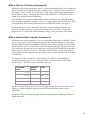
Additional MIDI In facilities which are part of the MIDI In and Out system
The MIDI In subsection of the MIDI In and Out system has these altered and additional
facilities:
•
The firmware’s Note Stack for storing previously played notes, which will be played
if they are still on when the currently played note is turned off, holds 8 notes, rather
than the 10 notes of the MIDI In (only) system . This means that 8 notes can be
played and held on in succession, and the last one played will drive the Synthesizer
DAC (which creates the voltage for the VCO, and so controls the VCO’s pitch) and
MIDI Out. When that note is turned off, the most recently played note, if it is still
on, with will control DAC voltage of the Synthesizer, but the Accent drive to the
Synthesizer will remain that of the first note which caused Gate to be turned on, as is
the case with the MIDI In (only) system.
There are 16 Note Stacks – one for each MIDI In Channel – to support the Dynamic
Channel Switching (DBS) system. This system works with the top note of the Note
Stacks of four adjacent MIDI In channels, such as those of channels 1, 2, 3 and 4, or
of 8, 9, 10 and 11, or 16, 1, 2 and 3. The top note of each channel’s Note Stack is
the note the Devil Fish would be playing if DBS was not enabled and the (Base)
MIDI In Channel (Parameter 0, see page 35) was set to this channel.
•
The Dynamic Bank/Channel Switching (DBCS) System has a number of facilities
concerning MIDI In. These are an advanced topic and are explained in Section 7 on
pages 58 to 105.
These facilities enable switching MIDI In Note reception between four contiguous
MIDI In channels – such as 4, 5, 6 and 7 – in response to MIDI In messages on
Channel 15 or 16 and/or (with appropriate switches and input sockets for
6
Installations 4 or 6) to the positions of two toggle-switches and the detection of two
Audio or CV signals. The reception of Control Changes, such as for Filter
Frequency, is unaffected by this switching. These messages are always received on
the Base MIDI In Channel, which is channel 4 in this example.
These facilities are only enabled after turning the machine on with a special
procedure involving the BACK button – as described on page 58 – which must be
repeated every time the machine is turned on and these facilities are to be used.
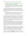
Facilities of the MIDI Out sub-system in the MIDI In and Out system
•
The machine sends MIDI Note On events on the same channel it receives on (by
default, channel 1) in one of three modes, which are automatically selected:
o Int Seq mode. Note pitches result from the Internal Sequencer when it is
playing a pattern, in Pattern Write, Pattern Play, Track Write or Track Play
modes. This includes the potentially complex set of notes which result from
Dynamic Bank Switching causing the Internal Sequencer to play notes from
different memory banks from one moment to the next.
o Ext CV mode. This is a CV-to-MIDI mode of operation. Note pitches result
from measuring the voltage of an externally applied Pitch CV, plugged into the
CV In socket – or, if no lead is plugged into this socket, from the notes generated
by the Internal Sequencer playing notes during Pattern Write mode, when it is
not playing the pattern. This is when the user is entering and altering pitch,
timing, Accent and Slide information. This enables the Devil Fish to function as
a CV to MIDI converter.
o MIDI In Follow mode. When the MIDI In system has reception of Notes and
Control Changes ON (hold TAP and press and release BACK), the MIDI Out
system replicates via MIDI Out Note On and Off messages the notes the MIDI In
system is playing on the Devil Fish, including the notes which result from
Dynamic Channel Switching.
Please see Section 7 below (pages 58 to 105) for explanations of MIDI Out functionality
regarding:
o Note On and Off events resulting from the Gate signals of the Internal
Sequencer, of the Gate In socket and due to more than +4 volts being applied to
the Slide In socket.
o Slide, including from the Slide In socket.
o Accent due to the Internal Sequencer, the Accent In socket and the Accent
button.
o Dynamic control of velocity values for non-Accented and Accented notes via
Control Changes 20 and 21 being sent to MIDI In.
o MIDI Out messages for Filter Frequency which follow those received on MIDI
In.
7
The exact behavior of the MIDI Out sub-system takes a lot of explaining, because there
are so many combinations of circumstances which can occur. For a fuller description of
this, please see the two tables on pages 46 and 47, which summarise most of the
distinctions between the three MIDI Out Note modes.
•
By default, the Devil Fish sends MIDI Sync messages to MIDI Out, in response to
whichever of the following sources are driving the Internal Sequencer. Please see
page 41 for further explanation, including how to disable the reception and/or
transmission of MIDI Sync.
o The internal Tempo system: the Tempo knob and the Run/Stop button and its
flip-flop.
o DIN/Roland Sync from an external source, via a Sync cable plugged into the
Sync Socket.
o MIDI Sync being received via a MIDI cable plugged into the Sync socket. (This
includes MIDI In being received via the special optional Devil Fish Sync Lead,
which enables the MIDI In sub-system’s decoding of MIDI In Sync to drive not
just the Devil Fish’s Internal Sequencer, but one, two or three DIN/Roland Sync
slave devices which are connected to the cable.)
8
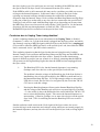
Quickstart and what to do with this User Manual
Initially, please read, or at least scan, Sections 0 and 1. This will give you an idea of
what the MIDI In and Out system is capable of. Within this, there are two complex subsystems which cannot be fully understood except by extensive further reading: the MIDI
Out sub-system and the Dynamic Bank/Channel Switching sub-system.
To use MIDI In initially, you can send the Devil Fish (by plugging the MIDI lead into
the Sync Socket) MIDI Sync (Start, Tempo Clock and Stop messages) and the Devil
Fish’s Internal Sequencer will respond to this by playing patterns or tracks. You can
send the Devil Fish both Note events and Control Change 1 (Mod Wheel) messages on
Channel 1 and the Devil Fish will (with the default Base MIDI In Channel of 1) play
these notes and respond to the Control Changes with changes to Filter Frequency.
When the Devil Fish MIDI In sub-system responds to the first Note event, it takes
control of the TB-303’s DAC (Digital to Analog Converter) which controls the pitch of
the Synthesizer’s VCO, so this is no longer controlled by the Internal Sequencer. The
MIDI In sub-system also drives the Gate signal to the Synthesizer. It is possible for the
MIDI In system to be doing this, and so playing notes on the Synthesizer, while the
Internal Sequencer is running in time with the MIDI Sync bytes which are also being
received. In these circumstances, the pitches produced by the Internal Sequencer will
have no effect, since it no longer controls the DAC. The Synthesizer Gate signal can be
turned on by either or both of the MIDI In sub-system or the Internal Sequencer.
Assuming you want the Synthesizer to play only the notes being received from MIDI In,
and your MIDI In source includes MIDI Sync bytes (Start/Continue, Clock and Stop),
then it is best to have the Internal sequencer playing a pattern without any notes.
(Alternatively, the Devil Fish can be configured not to receive MIDI In Sync, but at this
early stage of using the machine without wanting to read much of the manual, it is
easiest to select a blank pattern.)
See page 20 for how to enable and disable the reception of MIDI In Note and Control
Change messages by pressing the TAP and BACK buttons. The setting for not
receiving these is retained when the Devil Fish is turned off and on again, so if you later
find that it does not receive these messages when you want it to, perhaps the cause is
that you previously turned this off. Another possible explanation would be that the Base
MIDI In Channel is different from the channel on which the external device is sending
the Notes and Control Changes you want to play. See page 35 for how to change the
Base MIDI In Channel.
To use MIDI Out initially, I suggest you just plug the MIDI Out into a slave device (or
into several slaves via a MIDI Thru box or via an external sequencer) and concentrate
on music. The MIDI Out system replicates as much as possible the activity of the Devil
Fish Synthesizer, whether it is being driven by the Internal Sequencer, from external CV
and Gate or from MIDI In. The default MIDI Out channel is the same as the Base MIDI
In Channel, which defaults to 1.
There is only one User Definable Parameter which affects the MIDI Out system:
Parameter 8 (MIDI Out Channel) – as explained on page 44. The only reason for
changing this would be if you want the MIDI Out channel to be different from the Base
MIDI In Channel. While the MIDI Out system is quite complex, it is intended to do
what you want in all the circumstances, without any further configuration parameters.
9
If you want to change anything concerning MIDI In or MIDI Out, then you will
need to read Section 2 (The “Front Panel”), Section 3 (User Definable Parameters 0 to
8) and at least some of Sections 4 ( Interaction between the MIDI In system and the TB303 / Devil Fish) and 5 (Details of MIDI In features and User Definable parameters 0 to
8).
If you want to understand the MIDI Out system in detail, then you have quite a lot of
reading to do! Section 6 (MIDI Out further explanation) contains detailed descriptions
of the three modes of MIDI Out operation. For simplicity, section 6 assumes a single
MIDI In Channel – that is, no Dynamic Channel Switching.
If you want to use the Dynamic Bank/Channel Switching (DBCS) system in any way,
then you should first become highly familiar with all the MIDI In facilities and be
comfortable using the Devil Fish in general. The DBCS system cannot be understood
without extensive reading of Section 7. Furthermore, the MIDI In facilities of DBCS
will not operate unless the machine is turned on with a special pattern of button activity,
which is explained at the start of that section. This is because the DBCS system’s
behavior is complex and likely to be confusing if it was activated when you were not
expecting it.
Within your complete musical set-up, the Devil Fish with MIDI In and Out involves a
variety of interacting sub-systems:
1. The basic TB-303, with its internal Tempo Clock system, Sync Socket selection
of this, or an external source of DIN/Roland Sync (AKA Sync-24), Internal
Sequencer and Synthesizer – where the Synthesizer has been extensively
modified to be that of a Devil Fish.
2. The Devil Fish’s new controls, new CV, Gate etc. inputs, the new Audio Inputs
(Audio In to Filter and Audio In to Frequency Modulate the Filter) and Audio
Out (Audio Out from Filter).
3. The optional 32 Bank Memory system.
4. The Devil Fish MIDI In sub-system, as it operates without DBCS.
5. The Devil Fish MIDI Out sub-system.
6. The DBCS system, which is primarily an elaboration of the MIDI In system, but
which can also receive MIDI events to drive two bits to the default contacts of
the two 3.5mm sockets of the DBCS Detector circuits, toggle-switches and XOR
gate address bit inversion circuits (though there is an option for Dynamic
Channel Switching without these).
In the case where the Devil Fish has the 32 Bank Memory System and the full
DBCS installation, the signals sent to the default inputs of the two Audio or CV
Input sockets (if nothing is plugged into these sockets) will cause MIDI In
messages received on Channel 15 or 16 by the DBCS system to alter the
inversion of two 32 Bank Memory address bits, so affecting the patterns played
by the Internal Sequencer.
When you use one or both of these Audio or CV input sockets, then other signals
from your studio can dynamically alter the current Memory bank (Dynamic
10
Channel Switching – affecting the Internal Sequencer’s pattern playback) or the
current Effective MIDI In Channel (Dynamic Channel Switching), so switching
MIDI In reception between up to four contiguous MIDI Channels. The intention
of Dynamic Channel Switching is that the Devil Fish will be sent two, three or
four separate patterns of notes (or any notes at all, not necessarily repeating
patterns) via MIDI In, with MIDI channel 15 or 16 Note and/or Control Change
messages, toggle-switch manipulation and/or external Audio or CV signals
dynamically controlling which of these four channels notes are received on.
The MIDI In system is reasonably complex, and some effort is required to understand
how to alter its User Definable Parameters. The MIDI Out system is highly complex in
detail, but apart from altering User Definable Parameter 8 to select a different MIDI Out
Channel than the Base MIDI In Channel, there’s nothing to adjust and it should do what
you want musically without the need for understanding it fully.
The DBCS (Dynamic Bank/Channel Switching) system is highly complex and can only
be used after it and the rest of the Devil Fish sub-systems are understood reasonably
well.
Be sure to annotate this manual and add Post-It notes to identify pages of interest for
quick reference. I can’t imagine how this material could be useful in a purely electronic
form, such as by reading the PDF on screen. The Devil Fish is provided with A4 combbound versions of all the relevant User Manuals. There will not be a test of your
comprehension – I can’t remember all these details.
11
1 - Overall description
This MIDI In and Out system is an additional modification I can install in a Devil Fish
modified TB-303. It is not available as kit for someone else to install. I usually install it as
part of the Devil Fish mods, where I have provision for it on the Version 4.0 and later
printed circuits. It is also possible for me to install this system on Version 2.x or 3.x Devil
Fish modified TB-303s – by replacing the two original Devil Fish circuit boards with two
new ones.
Pages 5, 7 and 12 to 44 this manual primarily concern the ordinary facilities (not to the
Dynamic Bank/Channel Switching facilities) of the MIDI In system or sub-system. Some
parts of these pages concern the MIDI Out system too, and are highlighted in Green.
Pages 44 to 56 concern only the MIDI Out system. The MIDI Out system is implemented
by the same microcontroller chip as the MIDI In sub-system, but is conceptually and
functionally largely independent of this.
There is no MIDI Thru, but the MIDI Sync timing messages received via MIDI In are (by
default, this can be disabled with User Definable Parameter 8) replicated on MIDI Out. The
MIDI Out system has three modes of operation: Internal Sequencer Mode, External CV
Mode and MIDI In Follow Mode. In all three modes, the system reproduces via MIDI Out
the Filter Frequency Control Changes which are received via MIDI In. In MIDI In Follow
Mode, the notes – with Accent and Slide – which are received via MIDI In are replicated to
MIDI Out. This includes the way the Dynamic Channel Switching system can switch
between notes on four adjacent MIDI In channels to play a set of notes which does not exist
on any one of these: the MIDI Out system causes slave devices to play that the notes
produced by the Dynamic Channel Switching system.
The existing DIN socket is used for MIDI In – but it can still be used for Sync when not used
for MIDI In. The MIDI In system uses the TB-303's internal Digital to Analogue Converter
(DAC), so the control voltages and therefore oscillator pitches for each semitone in the are
identical to those produced by the internal sequencer. The Internal Sequencer has a five
octave range from C2 to C6 (MIDI note numbers 48 to 96). Without transposition, the MIDI
In sub-system receives MIDI note numbers 45 to 100 (as shown in the table on page 37),
which goes three semitones below and four semitones above the range of the Internal
Sequencer.
MIDI Out is via a short 5 pin DIN socket adaptor lead which plugs into a 3.5mm stereo
socket located on the rear panel of the Devil Fish, between the Sync socket and the
Tuning knob.
User Definable Parameters are settings which are altered via the BACK and TAP buttons,
with status indicated by a new Blue LED, which shines through the same ‘e’ in the Devil
Fish logo as the Red Gate LED. The values of the user-definable parameters are stored in
non-volatile memory within the MIDI In and Out system’s microcontroller chip. This nonvolatile memory does not depend on the TB-303’s C-cell batteries or on the Devil Fish’s
lithium battery, which ensures the TB-303’s standard memory system, or the 32 Bank
Memory system, retains its data at all times. So these settings remain after the machine has
been turned off and on.
The settings stored in non-volatile memory are:
1-
Whether or not the Devil Fish is able to receive MIDI In Note and Control
Change messages (see page 20).
12
Changes to this have effect immediately and are also stored immediately
into non-volatile memory. This is not one of the User Defined Parameters.
2-
The twelve User Defined Parameters numbered 0 to 11. For brevity, these
are sometimes referred to simply as “Parameters”, such as in “Parameter
7”.
Changes to the values of these have immediate effect on the Devil Fish,
but are only stored into non-volatile memory by a special pattern of
pressing the BACK and TAP buttons. If you have altered one of these
values and not yet pressed these buttons to store the new value to nonvolatile memory, and you do not want to do this, turn the Devil Fish off
and on again.
The MIDI In system receives Note Commands and some Control Change Commands on a
single, user-definable, MIDI channel, which is Parameter 0, the Base MIDI In Channel.
(The Dynamic Bank / Channel Switching system extends the reception of Note Commands
on one of four channels, being the Base MIDI In Channel plus 0, 1, 2 or 3.) It also receives
MIDI Sync: Start, Clock, Stop and Continue. The system ignores all other MIDI messages.
Brief descriptions of the MIDI In system’s and MIDI Out system’s capabilities are as
follows. Tables listing all the received and transmitted MIDI messages can be found in
Section 11, starting at page 110.
MIDI In Notes
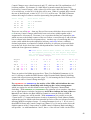
The full 4 octave range of the TB-303's internal sequencer is received – with the C on
the left of the TB-303 keyboard in Pattern Write mode (2 Volts) corresponding to MIDI
Middle C (note number 60). In addition, 3 additional semitones below and above this
range are also received, although the accuracy of the TB-303's VCO may not be ideal at
these voltages. The lowest MIDI note number received is 45 (A1 = 0.75 volts = 3
semitones below the internal sequencer's lowest C) and the highest is 100 (E6 = 5.333
volts = 4 semitones above the internal sequencer's highest C when the pattern is
transposed upwards by 12 semitones). The table on page 37 lists these note numbers
and voltages.
A transposition of +/- 24 semitones can be applied to the MIDI note numbers before the
notes are played within the above range, with Parameters 1 and 2 (page 36). There is no
pitch bend facility.
MIDI In Accent
Accent is turned on according to the note's Velocity being above a threshold. The
threshold is one of four preset values, according to the setting of Parameter 6 (page 41).
The default threshold, which the received note must equal or exceed in order to turn on
Accent, is 65. This is one above the velocity value of 64 which is usually sent by MIDI
keyboards which are not velocity sensitive.
MIDI In Slide
Slide can be turned on for “tied notes” – where one note starts before the last one is
released.
Slide can also be turned on via MIDI Control Change (AKA “MIDI Controller”) 65
13
(Portamento) or by a user definable Control Change number which also drives Sustain
(Gate). This facility is off by default, but can be turned on and made to respond to
Control Change numbers 1 to 19, by setting Parameter 5 (page 40) accordingly.
Sliding – slewing of the DAC voltage slowly from the previous pitch to the new pitch –
is a separate function from keeping the Gate on between what would otherwise be two
separate Gate pulses for two separate notes.
MIDI In Gate (Sustain)
In addition to normal Gate operation from the received MIDI notes, Controller 64
(Sustain or Hold) can be used to independently turn on the TB-303's Synthesizer Gate.
Another user definable MIDI Controller (the same as just mentioned for MIDI In Slide)
can also turn on Gate and/or Slide. This facility is off by default, but can be turned on
and made to respond to Control Change numbers 1 to 19, by setting Parameter 5 (page
40) accordingly.
MIDI In Filter Frequency
A user definable Controller can be used to drive the Filter Frequency, over a range of
about 5 octaves, in a similar manner to the Devil Fish Filter CV In socket. This MIDI In
control of Filter Frequency adds to, rather than replaces or overrides, the control exerted
by the Filter CV In socket and all the other internal signals which affect Filter
Frequency. This Controller Number defaults to 1 (Mod Wheel) but can be disabled, or
changed to any number 1 to 10, by Parameter 3 (page 38).
MIDI In Sync
The system receives MIDI Sync (Start, Continue, Clock and Stop) to drive the TB-303's
internal sequencer. With a suitable lead, such as the Sync Lead (see sync-lead/ page on
the Devil Fish website) the MIDI In system can also produce DIN Sync for external
devices in response to these received Sync messages. Please see page 41 for a full
explanation if MIDI Sync reception and transmission.
MIDI Out Notes
Here are brief descriptions of the three modes of operation, each of which is
automatically selected according to the circumstances:
•
Int Seq mode - when the Internal Sequencer is playing a pattern and MIDI
In notes are not being received. MIDI Out notes with note numbers 48 to 96
are generated in response to notes played by the TB-303’s Internal Sequencer
when it is playing a pattern (Pattern Write or Pattern Play modes) or playing a
pattern as part of a track (Track Write or Track Play modes). This is true even
when there is an external CV plugged into the CV In socket, which controls the
Devil Fish’s synthesizer.
•
Ext CV mode - when the Internal Sequencer is not playing a pattern and
MIDI In notes are not being received. MIDI Out notes are typically generated
in response to an external pitch Control Voltage which is plugged into the Devil
Fish’s 3.5mm CV In socket. The input range is 1.0 volts to 5.0 volts, which is
14
the normal range of operation of the TB-303 and its internal sequencer. This
generates MIDI notes with note numbers 48 to 96. The exception to this typical
usage is that Ext CV mode is also used when the Internal Sequencer is not
playing a pattern, but is in Pattern Write Step mode. In this case, in the absence
of a CV being input to the CV In socket, the MIDI Out notes will result from the
CV generated in the DAC as it is driven by the Internal Sequencer as it plays
individual notes as part of the Step mode writing and editing process.
•
MIDI In Follow mode - when MIDI In notes are being received. MIDI Out
notes result from notes received by the MIDI In system, including according to
the complex interpretation of Notes on four MIDI In channels with the Dynamic
Channel Switching system. This generates MIDI notes with note numbers 45 to
100.
In all three modes, MIDI In received Control Change values for the Controller number
which is selected for Filter Frequency will be replicated on MIDI Out, with the same
Controller number, on the MIDI Out channel. This is described more fully in the
subsection below entitled “MIDI Out Control Changes for Filter Frequency” (page 16).
In both Int Seq and Ext CV modes:
•
The MIDI Out notes result from the Gate signal which controls the Devil Fish
synthesizer, which is an OR of:
o The Gate signal created by the Internal Sequencer. (Int Seq mode: due to
the Internal Sequencer playing notes as it plays a pattern. Ext CV mode:
due the Internal Sequencer playing notes as part of Pattern Write > Step
writing and editing of notes.)
o The Gate signal from the Gate CV input socket.
o The Gate signal which results from the Slide CV Input socket being driven
with more than about +4.0 volts.
•
The Slide which can be applied to these notes, by way of tied note-on-note-off
(the new note starts before the old note ends), is controlled by the Slide signal
which controls the Devil Fish synthesizer, which is the OR of:
o The Slide signal produced by the Internal Sequencer.
o The Slide signal from the Slide CV Input socket, when it is above about
+2.3 volts.
•
The Accent which is applied to these notes, by way of choosing between two
velocities for non-accented and accented notes, is controlled by the Accent
signal which controls the Devil Fish synthesizer which is the OR of:
o The Accent signal created by the Internal Sequencer.
o The Accent signal from the Accent CV Input socket.
o The front panel Accent button.
In MIDI In Follow mode, the Accent state of the received notes which are sent to MIDI
Out is an OR of how the MIDI In system determines whether to Accent that note
(according to a user definable choice of four velocity thresholds – Parameter 6) and the
three Accent signals mentioned immediately above.
15
MIDI Out Velocities for Accented and Non-Accented Notes can be
controlled by MIDI In Control Changes
By default, at power on, the non-accented MIDI Out note velocity will be 64 and the
accented MIDI Out note velocity will be 127 (the maximum possible). These two
values can be altered while the MIDI Out system is running in any of the three modes,
by sending Control Change messages for Controller 20 (velocity for non-Accented
notes) and 21 (velocity for Accented notes) via MIDI In. In this manner, the dynamics
of the notes produced by the instrument(s) which are receiving the MIDI Out notes can
be altered dynamically, including a full range of 1 to 127 as velocities for both the nonAccented and the Accented notes.
When the values for Accented and Non-Accented notes are altered in this way, they are
stored in ordinary microcontroller memory, not in its non-volatile memory. So these
values will remain until the Devil Fish is turned off and on again.
This reception of MIDI In Control Change 20 messages on the Base MIDI In Channel is
always active. As explained below (page 20) this is not affected by the setting Turning
on and off the reception of MIDI Notes and Control Changes.
No transposition of MIDI Out notes with respect to the pitches played on
the Synthesizer
The MIDI In sub-system (including with Dynamic Channel Switching) can transpose
the note numbers of MIDI In notes with a range of plus or minus two octaves, before it
is used to drives the Devil Fish synthesizer and therefore MIDI Out notes. There is no
transposition between the pitches of the Devil Fish synthesizer and the notes numbers
used for MIDI Out.
So the MIDI Out notes may be transposed with respect to MIDI In notes.
MIDI Out Control Changes for Filter Frequency
The MIDI Out system cannot sense the position of the Filter Frequency (“CUTOFF”)
knob. Nor can it sense any voltage which might be applied to the Filter Frequency CV
input socket, or the other signals which affect the Filter Frequency of the Synthesizer.
However, it always replicates on MIDI Out whatever Filter Frequency values it receives
from MIDI In, assuming the reception of MIDI In Notes and Control Changes is enabled
(hold TAP and press and release BACK – see page 11). This occurs in all three MIDI
Out modes – Int Seq. Ext CV and MIDI Follow. This replication of MIDI In received
Control Change data is obviously required for the MIDI Follow mode. However, when
the machine is not receiving MIDI Notes – meaning the MIDI Out mode is either Ext
CV or Int Seq – then the MIDI In system can still receive Control Changes for Filter
Frequency, which will affect the Synthesizer as it plays notes arising from the Internal
Sequence and/or external CV In and Gate In.
The MIDI Out Control Changes which carry the Filter Frequency values are on the
MIDI Out channel (Parameter 8). The Control Change number for these outgoing
messages is the same Control Change number as is currently selected (Parameter 3) for
receiving MIDI In Filter Frequency Control Changes.
16
Not every received Filter Frequency Control Change will generate a corresponding
MIDI Out Filter Frequency Control Change. The two circumstances where one will not
be generated are:
1. If the most recently received MIDI In Filter Frequency Control Change had the
same value as the previous one.
2. If there is a high level of MIDI Out activity due to Sync messages (primarily
Sync Clock messages) and/or Note On and Off messages, both of which have a
higher priority than these Filter Frequency Control Change messages.
Due to point 2, it is possible that a high rate of incoming Filter Frequency Control
Changes will lead to a smaller number of outgoing Filter Frequency Control Changes,
even if each incoming message has a different value. This will result in a slight
reduction in the ability of slave devices to respond to the Filter Frequency Control
Changes which have been received. This is likely to be inaudible.
MIDI Out Sync
MIDI Out Sync is enabled by default but can be disabled with Parameter 7. Please see
page 41 for a full explanation. When this is enabled, Sync messages (Run, Clock and
Stop) are sent to MIDI Out as a result of:
•
The TB-303’s Internal Tempo system: the Tempo knob and the Run/Stop
button with its internal flip-flop.
•
External DIN Sync In via the Sync socket.
•
MIDI In Sync.
Firmware updates via installing a new microcontroller chip
The MIDI In and Out system’s microcontroller (PIC16F1936) is a 28 pin DIP device
which can be replaced with a new one containing later versions of the firmware, to fix
any bugs and to implement new features. This involves completely dismantling the TB303 / Devil Fish and reassembling it – so this should only be undertaken by an
experienced technician. The microcontroller is small and easy to send in the post.
The Sync / MIDI In socket is not an ordinary MIDI In socket
The Sync / MIDI socket of the Devil Fish with MIDI In is not an ordinary MIDI In
socket. The two outside pins carry Run/Stop and Clock. This means that devices
such as the Evolution 225C (and no-doubt other keyboards from this company:
www.evolution.co.uk ) should not be plugged into the Devil Fish, except with a lead
which does not connect to the outside pins.
The Evolution 225C has +5 volts and a 5 volt MIDI signal on the outside pins so that it
can be powered by a special lead which plugs into a PC sound card's joystick
connector. Please use a special lead, or an ordinary lead with the outside pins broken
off, between such a keyboard and the Devil Fish’s MIDI In socket (the Sync socket).
Another approach is to plug the keyboard into some other MIDI device and use the Thru
of that device to drive the Devil Fish.
17
2 - The “Front Panel”
The MIDI In and Out system uses a very minimal Front Panel – the user-interface by which
User Definable Parameters (for brevity, below, often referred to as just “Parameters”) can be
changed and by which several other functions can be activated:
The BACK button and the TAP (NEXT) button are the two Input elements.
A Blue LED mounted so it shines through the ‘e’ of the Devil Fish logo is the sole
Display element.
The TB-303's CPU sees the BACK and TAP buttons too, so pressing them for the purposes
of controlling the MIDI In system may also affect what the TB-303's CPU does. BACK and
TAP have little or no effect when playing patterns in Pattern Play or Pattern Write modes,
except that when the internal sequencer is stopped in Pattern Play mode, pressing TAP will
cause it to play a high C note which lasts until the TAP button is pressed again or until some
other action occurs. (See Section 10 below: The Pesky C4 Note in Pattern Play Mode, on
page Error! Bookmark not defined..)
When writing patterns, BACK and TAP (NEXT) directly affect the writing operation, so it
is best not to try to control the MIDI In system while writing patterns. Likewise for the even
more complex use of these buttons when writing tracks.
This minimal “Front Panel” system will drive you bananas if you don't read the
following section clearly! Please pay close attention to these instructions regarding
Pressing, Holding and Releasing these two switches. The order and timing of these actions
is crucial.
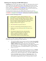
Initialising the User Definable Parameters
The Microcontroller at the heart of the MIDI In and Out system uses non-volatile
memory, which is completely independent of the memory of the TB-303 and which
does not rely on any batteries. If, for some reason, you want to initialise the values of
the twelve User Definable Parameters to the defaults listed in the table on page 15
(include receiving MIDI Notes and Controllers on Channel 1, receiving MIDI In Note
and Control Change messages and receiving and transmitting MIDI Sync), turn the
machine on whilst holding both BACK and TAP.
The Blue LED will flash triple flash – triple flash – triple flash.
Release the BACK and TAP buttons during or after these flashes and the machine will
be ready for ordinary operation – except that it does not recognise any of the button
combinations listed below. To use these, turn the machine off and on again.
Firmware version display
To display the version of firmware programmed into the MIDI In and Out system’s
microcontroller, turn the machine on whilst holding the BACK button but not the
TAP button. The Blue LED will continually cycle through a pattern of varying
brightness. A long moderate brightness period is followed by three dim periods,
within which 0, 1 or more bright flashes may be inserted. The number of flashes
indicates the software version. Version 2.1.0 is indicated by two flashes in the first
dim period, one in the second dim period and none in the third. In this mode, the
microcontroller is not receiving or transmitting MIDI or driving the TB-303 hardware.
To restore normal operation, turn the machine off and on again.
18
Power-on display of whether Notes & Control Changes are being
received
When the machine is turned on normally, or as described below for disabling Blue
LED display of MIDI In activity, the Blue LED will indicate the state of Reception of
MIDI Notes and Control Changes (see page 20).
If this is enabled, which is the default, the LED will display in 0.5 second intervals
bright, dim, bright, dim.
If it is disabled, then the LED will display double-flash – double-flash – doubleflash – double-flash.
Blue LED MIDI activity display and how to disable it
The Blue LED which shines through the Red Gate LED in the ‘e’ of the Devil Fish
logo has six functions.
The Blue LED circuit may cause very slight interference with the audio output. Its
operation for functions 5 and 6 below can be disabled, by turning the machine on
with the TAP button pressed, and the BACK button not pressed.
The six functions are:
1. Acknowledging the Initialise all Parameters command, as described above.
2. Displaying the firmware version. as described above.
3. Power on display of whether the MIDI In system is enabled to receive MIDI Notes
and Control Changes, as described above.
4. Indicating the status of “Front Panel” operations – the pressing and releasing of the
BACK and TAP buttons.
5. Indicating successfully received MIDI In messages with brief flashes, as described
in the section below The Blue LED. This function is normally on, except for when
“Front Panel” operation is in progress and except when it is disabled as is described
below.
6. Indicating the ending and starting of notes when the DCS (Dynamic Channel
Switching) system is activated and is operating in Immediate mode, rather than
Delayed mode and the Effective MIDI In Channel is changed from the current one
of the possible four to one of the other three possible channels.
The notes themselves have been previously received on the previous and/or the
current Effective MIDI In Channel and the most recently received Note On of these
on the previous Effective MIDI In Channel has previously generated a flash when it
was received. If this note is turned off at this instant, there will be a flash to
indicate this. Likewise if a note previously received on the new Effective MIDI In
Channel is turned on at this instant, due to the Effective MIDI In Channel now
being this channel, the LED will also flash, even though that note was received at
an earlier time. If both these occur: turning off an old note and turning on a new
note, there will still be one flash. These note off and on events are caused by a
change in the Effective MIDI In Channel due to either reception of a MIDI In Note
19
or Control Change event (in the absence of any input sockets, detector circuitry,
LEDs, toggle-switches and bit inversion circuitry) or by a change in the two bits
produced by this address bit inversion circuitry.
Turning on and off Reception of MIDI Notes and Control Changes
This is a single setting, which is stored immediately in non-volatile memory. So
whatever change you make will remain after the machine is turned off and on.
The title Reception of MIDI Notes and Control Changes is a simplification of the true
function of this setting. The three paragraphs below in bold explain the exceptions.
Before following either of the procedures below, make sure that the machine is not in
the middle of the “Altering the value of a parameter” operation, as described on pages
12 to 14. If the machine is in this state, press and hold both BACK and TAP buttons
for a few seconds, until there is either a series of double flashes (a normal exit from
editing a parameter, involving saving the potentially altered value to non-volatile
memory) or a continual series of flashes at about 6 Hz (an exit before a parameter has
been selected for editing).
This setting does not affect MIDI Out for Notes or Sync. These are typically on at
all times, except as described below (User Definable Parameter 7: Receive and
Transmit MIDI Sync, page 41) where the reception and transmission of MIDI Sync
can be disabled.
There are three exceptions to the general principle that this setting controls the reception
of MIDI In Note and Control Change messages:
1-
It does not affect the reception of Control Changes for Controller 20 and
21, which are used to alter the Velocities of non-Accented and Accented
MIDI Out notes.
2-
It does not disable the reception of Control Changes for Controller 1 to 10
for Filter Frequency, if Parameter 3 (page 38) is set to values between 11
and 20, which select Controller numbers 1 to 10 respectively. If it is
desired to disable Filter Frequency Control Change reception in this way,
please use values 1 to 10.
3-
Nor does this affect the Dynamic Bank/Channel Switching (DBCS)
system’s reception of Notes and Control Changes on channel 15 or 16 (as
set by User Definable Parameter 10, page 80) for the purposes of generating
two bits which may be used directly for Dynamic Channel Switching
(Installations 3 and 5) or to drive the default contacts of the two 3.5mm Audio /
CV Input sockets of the DBCS hardware (Installations 4 and 6).
20
Here is the procedure:
Turn ON reception of MIDI Notes and Control Changes
Hold down the TAP button.
Press and release the BACK button within a second or so.
While both buttons are pressed, the Blue LED will flash rapidly. After the Back
button is released the Blue LED will stay ON for 0.8 seconds and will then turn
OFF.
Release the TAP button.
After reception is turned on, the MIDI In system will not take control of the TB-303's
DAC (to control the pitch CV and so the pitch of the Synthesizer’s Oscillator, assuming
nothing is plugged into the CV In socket an the back panel) until a Note On is received
on the correct MIDI channel, within the currently valid range of note numbers. This
will be the Base MIDI In Channel if DCS (Dynamic Channel Switching) is not enabled,
or if it is enabled, one of the channels in the set starting with this channel, and going up
by 1, 2 and 3 channels, with wraparound from 17 to 1.
This state of the microcontroller controlling the DAC will still be maintained after no
more MIDI events are received, even if the MIDI In lead is removed from the
Sync/MIDI socket. This state prevents the Internal Sequencer from controlling the DAC
and therefore from controlling the Synthesizer’s pitch.
The MIDI In system will begin to drive the Filter Frequency only after a Control Change
for this is received. Slide and Gate (Sustain) can be driven by several types of MIDI In
Control Change messages (as described above, on pages 13 and 14) , as well as after a
Note On event has been received.
In order to return control of the DAC etc. to the TB-303's internal sequencer so the
MIDI In system no longer drives Gate, Slide, Accent or Filter Frequency, use the
following procedure:
Turn OFF reception of MIDI Notes and Control Changes
Hold down the BACK button.
Press and release the TAP button within a second or so.
While both buttons are pressed, the Blue LED will flash rapidly. After the Tap
button is released the Blue LED will stay ON for 0.2 seconds and will then turn
OFF.
Release the BACK button.
The control of the reception of MIDI Sync is separate – see Parameter 7 in the table and
descriptions below, on pages 25 and 41 respectively.
21
Altering the value of a User Definable Parameter
There are twelve User Definable Parameters, numbered 0 to 11, which can have their
values changed with the following procedure. The details of Parameters 0 to 8 are listed
on page 25 and the details of Parameters 9, 10 and 11 – which only concern Dynamic
Bank/Channel Switching, are listed in a subsection which starts at page 76.
Please be aware that pressing the TAP button in Pattern Play mode can cause the
Internal Sequencer to play a sustained C4 note, as described in Section 9 - The Pesky C4
Note in Pattern Play mode (page Error! Bookmark not defined.).
The MIDI In and Out system continues to receive MIDI and play notes etc. while a
Parameter’s value is being altered – the effects, if any, of the new value take place
immediately. Likewise, while a Parameter’s value is being altered, the MIDI Out
system continues to generate MIDI Out Notes and Sync messages, unless the
changed value directly affects this.
The final step writes the altered value into non-volatile memory. If this final step is not
performed, the changed setting will remain in ordinary microcontroller memory until the
machine is turned off, and the operation of the machine will be controlled by this
setting. However, when the machine is turned on, this altered value will no longer exist
and the Parameter will be set to whatever value was previously stored for this Parameter
in non-volatile memory.
Entering Parameter Select mode
Press and Hold both BACK and TAP buttons, for as long
as it takes for the Blue LED to stop flashing, which
will be about 4 seconds.
While the two switches are both pressed, the Blue LED will flash repeatedly
very quickly. After about 4 seconds, the flashing will stop and the Blue LED
will turn ON continually.
It doesn't matter whether you press BACK or TAP first, or how long after pressing the
first switch you press the second.
Release both switches.
The Blue LED will turn OFF.
(If you release either switch before the Blue LED turns on continually, then the MIDI In
and Out system will not enter Parameter Select mode. The system will resume normal
operation once both switches have been released.)
22
Selecting which parameter to alter
If you want to alter the first parameter – Parameter 0: MIDI Receive and Transmit
Channel (page 35) – then there is nothing to do at this stage, since this is parameter 0.
For other parameters 1 to 7 (table on page 25), or for parameters 8 to 11 (the tables on
the two pages following page 76), the Parameter number is how many times the BACK
button should be pressed:
Press and Release the BACK button the number of times
indicated in the table. For instance, for Parameter 7,
press and release the BACK button 7 times.
The Blue LED will flash briefly each time the BACK button is released.
Once you have done this the appropriate number of times – including, for Parameter 0
as just mentioned, not pressing the BACK button at all – perform the next step which
tells the MIDI In and Out system which Parameter you will be altering the value of:
Press and Release the TAP button.
The Blue LED will flash once.
(If, before performing the above step, you decide not to change the value of a Parameter,
press and hold both BACK and TAP for about 3 seconds. During this time, the LED
will not light, but at the end of the time, it will flash with a distinctive sequence of
double flashes. These double-flashes indicate that your command to exit has been
accepted. Release the buttons and the MIDI In and Out system will resume normal
operation.)
Altering the selected parameter’s value
The parameter you selected is now ready to be incremented (made one higher than it
currently is) with the BACK button or decremented (made one lower) with the TAP
button.
+ Increment the parameter:
Press and Release the BACK button.
– Decrement the parameter:
Press and Release the TAP button.
The Blue LED will flash briefly once for either of the above actions except
when the parameter has reached its minimum or maximum value.
Each parameter has a minimum and maximum value. If you Decrement when it is at its
minimum, or Increment when it is at its maximum, the value will not change and the
Blue LED will flash for a longer time. If you changed the value of the parameter to a
new state, then the Blue LED will flash for a short time.
There is no display of the parameter’s current value, but you can find the value by
stepping it down with TAP until it reaches is minimum, which is visible by a longer
flash of the Blue LED when you try to reduce it further from this value. For instance, if
the original value was 3 and the minimum value is 0, then it will take three presses of
the TAP button to change the value to 0, each of which will generate a normal flash. A
fourth press of the TAP button will attempt to reduce the value from its minimum, and
23
this will be indicated by a long flash. In this example, with a minimum value of 0, a
double-flash on the fourth press of the TAP button shows that the original value was 3,
so pressing the BACK button 3 times will restore the original value.
Similarly, to determine the current value, you can step up to the maximum value with
the BACK button, until there is a longer flash of the Blue LED, indicating that the
previous press of the BACK button had taken the value to its maximum.
Changing the value of a parameter has immediate effects on the MIDI In system.
Changing the values of some of the parameters has an immediate effect on the
MIDI Out system. Furthermore, changes to the values of some parameters cause
specific actions, such as clearing received notes, Accent, Slide etc. if the Base MIDI In
Channel is changed. These are explained in the detailed information below on each of
the parameters.
The changed value of the parameter will not be written into non-volatile memory
unless the next step is performed.
If you wish to abandon whatever change you just made to the parameter, turn the
machine off. Turning it on will restore the value to whatever was stored in non-volatile
memory.
Saving to non-volatile memory and returning to normal operation
Whether or not you have altered the value of a parameter in the step above, to return to
normal operation, you must perform the following procedure – which also writes the
new value (or the original value, if unchanged) to non-volatile memory.
Press and hold both the BACK and TAP buttons until the
Blue LED flashes with a distinctive double flash
pattern. This will involve holding both buttons for
about 3 seconds.
When you have pressed and held them for long enough, the Blue LED will flash with a
distinctive double-flash pattern. This is the signal to:
Release both buttons.
after which the Blue LED will turn OFF and the MIDI In and Out system’s “Front
Panel” will be in normal operation mode.
24
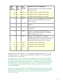
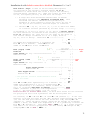
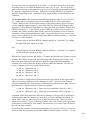
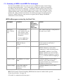
3 - User Definable Parameters 0 to 8
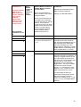
User Definable Parameters 0 to 11 are accessed and altered by the procedure described
immediately above – Altering the Value of a parameter, starting on page 22. Each parameter
0 to 8 is discussed in greater detail in Section 5 below on the page numbers shown in blue.
Parameters 9, 10 and 11 are described in Section 9: Dynamic Bank/Channel Switching.
Name of
parameter
User Definable
Parameter number
Range &
(default)
Function
More details on
page xx
= number of presses
of the BACK button to
select this parameter
before pressing TAP
Base MIDI In
Channel
35
0 (None – just press
TAP.)
1 – 16 (1)
Selects which channel will be used for receiving
Note and Controller messages from MIDI In.
MIDI In
Transpose
36
Enable
1
0 – 2 (0)
0 = No transposition.
1 = Transpose Up.
2 = Transpose Down.
MIDI In
Transpose
Amount
2
0 – 24
(12)
Number of semitones to transpose the MIDI note
number up or down before playing a note on the
Devil Fish synthesizer.
MIDI In
Filter
Frequency
Controller 38
3
0 – 20 (1)
0 = Disabled.
1 = Controller 1, which is Mod wheel.
2 to 10 = this controller number. 11 to 20,
controller numbers 1 to 10, but always operating,
rather than being turned off when reception of
MIDI In Notes and Control Changes is disabled.
MIDI In
Slide on Tied
40
Notes
4
0 – 1 (1)
0 = Disabled.
1 = Turn on Slide when a new note is started
before the previous one ends.
MIDI In
Sustain-Slide
Controller 40
5
0 – 19 (0)
0 = Disabled.
1 = Mod wheel.
2 to 19 = this controller number.
MIDI In
Accent Velocity
Threshold 41
6
0 – 3 (0)
The value which Note On Velocity must equal or
exceed in order that Accent will be turned on:
0 = 65*, 1 = 80, 2 = 100, 3 = 120.
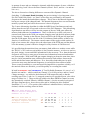
36
Red bold = default
* 64 for MIDI In V1.0.0 to V1.0.3.
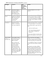
Receive and
7
Transmit MIDI
Sync
41
0 – 5 (1)
0 = Receive Off.
1 = Receive ON.
2 = Receive ON.
3 = Receive Off.
4 = Receive ON*.
5 = Receive ON*.
0 – 16 (0)
0 = Transmit on the MIDI In channel
(Parameter 0, above).
1 to 16 = Transmit on this channel.
* Disables the Unplug
Timer. See page 41 for
full details
MIDI Out
Channel
8
44
Transmit Off.
Transmit ON.
Transmit Off.
Transmit ON.
Transmit ON.
Transmit Off.
25
“Base” in “Base MIDI In Channel” means that this Channel number is the lowest of four
Channel numbers on which the Devil Fish will receive note information, when Dynamic
Channel Switching is used. For instance, if it is set to 3, then the Devil Fish can receive,
according to the actions of Dynamic Channel Switching, on channels 3, 4, 5 or 6. When
Dynamic Channel Switching is not used, this is the sole MIDI In channel. When Dynamic
Channel Switching is being used, this channel is still used for receiving Control Changes.
26
4 - Interaction between the MIDI In system and the TB-303 / Devil Fish
A full understanding of the various parameters and features requires a good understanding of
the three elements of hardware – the basic TB-303, the Devil Fish enhancements to it and
how the MIDI In system interfaces to these.
The standard TB-303
The TB-303 can be divided into two sections: Internal Sequencer and Synthesizer.
The Internal Sequencer section comprises:
The CPU chip (a 4 bit NEC microcontroller).
Battery backed-up memory – three 1024 x 4 bit static RAM chips.
Push-button switches, rotary switches and LEDs.
The Sync section:
Run/Stop button and flip-flop.
Tempo pot and oscillator.
Sync socket, which switches the above two to its outer pins and to the CPU
unless a lead is plugged into it, in which case, the lead can drive these pins.
The CPU contains firmware built into the chip which makes it respond to all the above
and so perform the functions of the Internal Sequencer. This involves reading and
writing data from and to the memory and controlling the Synthesizer section with the
following signals:
A 6 bit DAC (Digital to Analogue Converter) which provides a voltage between
1.0 and 5.0 volts, in 1/12 volt steps. This voltage is subject to a Slide process and
made available at the CV Out socket. (Its range is 1 to 64 steps of 1/12 volt each,
but below 1 volt and above 5 volts it is not necessarily accurate and the VCO
tracking of these voltages is less accurate than in the 1.0 to 5.0 volt range.
A Gate signal which is high when a note is ON. This is available at the Gate Out
socket as an approximately +6 volt signal.
An internal Slide signal which controls the slewing of the DAC’s CV (to the
Synthesizer's VCO and the CV Out socket) so that it takes a fraction of a second
to slew from the voltage of the previous note to the voltage of the new note.
An internal Accent signal which alters the way the Synthesizer works. (See the
Devil Fish User Manual for more information on Slide and Accent.)
The TB-303's Sync section consists of two front-panel circuits – a Tempo Clock
oscillator and a Run/Stop switch, flip-flop and LED – and a special 5 pin DIN socket.
This socket uses the middle pin (2) for ground (as does MIDI) and the two outside pins
(1 and 3) for the Run/Stop and Clock signals, respectively. (Pin 4 is also an input for
the TAP function and Pin 5 for some undocumented function. These are not normally
used in any Sync arrangement, and these functions are removed when the MIDI In and
Out system is installed.)
Normally, with nothing plugged into the Sync socket, a two-part switch in the socket
connects the local Run/Stop signal (generated by the Run/Stop switch and its associated
flip-flop) to pin 1 – and the Clock signal, from the Tempo oscillator to pin 3. These are
both +5 volt signals. 0 volts on the Run/Stop pin means that the TB-303’s Internal
Sequencer will not play a pattern or track, but is ready to start or write a pattern or track,
27
according to the MODE switch. +5 volts or more (up to + 15 volts) on the Run/Stop pin
tells the TB-303’s Internal Sequencer to “Run”: play a pattern or the patterns in a track,
according to the pulses which arrive on the Clock pin. The positive (rising) edge of
these pulses (again typically +5 volts, but perhaps as high as +15 volts), on the Clock
pin tells the Internal Sequencer that this is the start of a 1/24th of a quarter note.
The Clock circuit is normally a free-running square-wave oscillator – but it is reset and
made to restart with a slight delay when the Run/Stop button is pressed so as to turn
Run/Stop on. This ensures that when the Run/Stop signal goes high, the Clock signal is
low – and that there will be a delay of about 7 msec before the rising edge of the first
Clock pulse. This delay is musically unimportant, but is vital to allow the TB-303's
CPU to recognise this first Clock pulse, rather than miss it while the CPU is responding
to the rising edge of the Run/Stop signal.
If a plug is inserted into the Sync socket, without activating the switch, pins 1 and 3
function as outputs for the Run/Stop and Clock signals respectively. This can be done
by partially inserting the plug, or by removing its shell (or part of the shell) so it doesn't
press against the white rod inside the top of the Sync socket. This is not a standard part
of TB-303 functionality, but it can be useful. (For further discussion, see Section 9
below: Advanced use of the Sync-MIDI-In socket.)
If a plug is inserted normally into the Sync socket, this activates the two-pole normally
closed switch at the back of the socket, which disconnects the local Run/Stop and Clock
circuits from the socket's pins 1 and 3. The idea is that the lead which has been plugged
in will drive these pins. The voltage levels for receiving Run/Stop and Clock are not
critical – low should be 0 to maybe 1 volts and high should be between 3 and 15 volts.
So in normal operation – whether an external Sync source is plugged into the TB-303,
or whether nothing is plugged in and the local circuits drive pins 1 and 3 – these pins
have a valid Run/Stop signal and a valid Clock signal. The CPU sees these signals and
uses them to drive most of its operations.
The Run Battery LED on the front panel is turned on by a sufficiently high voltage on
the Run/Stop pin of the Sync socket (it has a lower threshold than that of the circuit
which senses this voltage for the CPU) AND the power supply voltage sensor circuit is
sufficiently activated. If this LED is dim, this means that the LED driver circuit senses
that the Run/Stop signal on the Sync socket pin is higher than its threshold AND, due to
low battery voltage or an inadequate external power supply, the TB-303 is not receiving
a high enough voltage to function reliably.
Without a regular Clock signal, such as dozens of pulses a second, the CPU will not
play any notes, flash any LEDs or respond normally to front panel button activity.
The Sync system is a two-signal input to the TB-303’s CPU. The TB-303’s CPU does
not drive the Sync socket. In a TB-303 without modification such as this MIDI In and
Out system, only an external cable, or the internal Run/Stop and Clock circuits drive the
socket and therefore these two inputs to the CPU.
(TB-303s may have broken solder joints at the Sync socket and its switch which prevent
the CPU sensing the Run/Stop signal and/or Clock signals. Without these, the CPU will
not flash the front panel LED lights, will not respond to buttons being pressed and/or
will not play patterns or tracks.)
28
Normal note-playing activity in the TB-303, when playing or writing patterns or tracks,
involves:
•
The CPU latching a 6 bit number into the DAC.
•
The CPU selecting whether or not the Slide circuit causes a slow slew in how the
new DAC voltage drives the VCO and CV Out socket.
•
The CPU turning the Accent signal on or off.
•
The CPU driving the Gate signal to the Synthesizer and Gate Out socket.
The standard TB-303 has no inputs for CV (to drive the VCO), Gate, Accent, Slide or
Filter frequency.
The Devil Fish Modifications add a number of inputs and new sources of control for
CV, Gate, Accent, Slide and Filter CV. The Devil Fish mods also add an Accent Out
socket – a +6 volt signal which can be used to drive other equipment, such as one or
more other Devil Fishes. Here are descriptions of the four signals as they are handled in
the Devil Fish without MIDI In, and in the Devil Fish with MIDI In and Out. The
MIDI In and Out details are in bold blue text.
Devil Fish CV In
The TB-303 CPU drives the 6 bit DAC, which has in internal impedance of 100k ohms.
In the TB-303, this is connected directly to a the Slide circuit, which can cause a slow
slew when the voltage changes, via a 0.22uF capacitor. In the Devil Fish, the DAC
drives a normally closed terminal of the Devil Fish's CV In socket. When nothing is
plugged into this socket, the DAC signal goes to the Slide circuit, via an over-voltage
protection circuit (3.3k ohms with some diodes which do not normally conduct) and the
new Slide pot (0 to 500k ohms). When an external CV is plugged into this socket
(probably with a much lower impedance than 100k ohms, meaning that it drives the
socket in a more robust fashion than the relatively weak 100k ohm impedance of the
DAC) the voltage from the DAC is ignored and input voltage goes via the over-voltage
protection circuit and the Slide circuit, slewing according to (the impedance of the input
signal + 3.3k ohms + the value of the Slide pot) whenever the Slide signal is on.
The output of the Slide circuit goes to the VCO, the Filter Tracking pot and the TB303's CV Out socket.
The MIDI In and Out system is the same as the above, except that the PIC
microcontroller in the MIDI In system can take control of the DAC from the TB303's CPU. When this happens, if the TB-303 CPU drives the DAC as part of
playing a note, the DAC voltage will be controlled solely by the MIDI In and Out
system's microcontroller. Plugging a lead into the CV In socket will mean that the
VCO, Filter Tracking pot and CV Out socket are driven by whatever signal is on that
lead. This means the output of the DAC, and therefore the pitches received from MIDI
In, will be ignored.
There is a potential problem with some Devil Fishes: an occasional intermittent poor
connection in the CV In socket's normally closed function means that the VCO pitch
drifts, remains static, or is way out of tune. The solution is to insert a plug a few times
into the socket, so the contacts get some movement. This is discussed more fully in the
Devil Fish User Manual in the section regarding reliability.
29
Devil Fish Gate
There are three signals which can turn on the Gate – for the Synthesizer Gate, the Gate
Out socket and the Red Gate LED in the ‘e’ of “Devil”.
1. The TB-303 CPU's Gate signal.
2. The Devil Fish's Gate In socket.
3. A voltage above about +4.0 volts on the Slide In socket will also turn on the Gate.
(This was not true for Devil Fishes prior to version 2.1D, 2003-11-11.)
These are ORed – one, any two or all three of them being active will turn on Gate.
The MIDI In and Out system drive the Gate in a similar way – an OR
arrangement of the above three signals with its own Gate signal. The MIDI In and
Out system cannot turn off the Gate if it is turned on by any of the above.
If the TB-303's CPU was turning the Gate on continually, the MIDI In system would not
be able to make it go on and off. If the MIDI signal contains no Sync (Start, Clock etc.)
the Internal Sequencer is unlikely to be running, because plugging a lead into the Sync
socket will open the switches and disconnect the TB-303's internal Run/Stop signal
from pin 1, and therefore from the Run/Stop input of the CPU. This will cause the TB303's CPU to deactivate its Gate signal. However, if the MIDI lead was only partially
inserted, or was modified so as not to activate the switch, then the TB-303's CPU could
be driving Gate whilst the MIDI In system is trying to turn Gate on and off. This might
be musically useful, but is more likely to be troublesome. (For further discussion, see
Section 9 on page 107.)
With an ordinary MIDI lead, properly inserted, there could be a situation in which the
TB-303's CPU is activating Gate at the same time as the MIDI In and Out system is
trying to play notes by activating the Gate. This would occur when these three
conditions are true:
1. The MIDI In system is configured to receive MIDI Sync, which is the default
arrangement.
2. The MIDI signal includes Clock bytes and at least one Start or Continue byte,
which causes the MIDI In system to turn on Run/Stop (pin 1 of the Sync socket,
and as an input to the TB-303's CPU and so its Internal Sequence) and to provide
Clock pulses (on pin 3, and also to the CPU and so its Internal Sequencer).
3. The TB-303 is currently set up to play a pattern, or track, such that the pattern it
plays contains some notes.
In the typical situation with an external MIDI sequencer which puts out Sync bytes,
there are two ways of avoiding this problem of the TB-303 CPU (Internal Sequencer)
driving the Gate when you really want to be controlling the Synthesizer entirely from
MIDI In. Either of these approaches will solve the problem:
1. Disable the reception of MIDI Sync (Parameter 7 in the User Definable
Parameters section, page 41.) or:
2. Make sure the TB-303 is in Pattern Play (or Write) mode on a blank pattern.
30
Devil Fish Slide
There are two signals which can turn on the Slide circuit. (This is not the same as
turning on the Gate to tie two otherwise separate periods of Gate on into a single
period. The TB-303's CPU, when playing two notes with Slide, does this, leaving the
Gate on as it changes the DAC voltage, whilst turning on the Slide signal to cause the
resulting voltage to the VCO to slew slowly.)
1. The TB-303 CPU's Slide signal.
2. The Slide signal which results from the Devil Fish Slide input socket having more
than about 2.3 volts applied to it.
The MIDI In and Out system can override the TB-303 CPU's Slide signal and the
Devil Fish Slide input socket.
When the MIDI In system is driving the DAC, it doesn't matter whether the TB303 CPU or the Slide input socket is driving the Slide – the MIDI In system will
control Slide irrespective of these. This overriding begins with the first note
played by the MIDI in sub-system in response to MIDI In. The override is not
activated simply by the MIDI In sub-system being ready to receive notes. A note
must be received first. Once this happens, the MIDI In system will control Slide,
according to Tied Note Slide and the Slide-Sustain Controller – until the reception
of notes is turned off by holding down the BACK button and pressing and
releasing the TAP button (page 20).
Devil Fish Accent
There are three signals which can turn on the Accent to the Synthesizer, which also
drives a +5 volt signal to the Devil Fish's Accent Out socket.
1. The TB-303 CPU's Accent signal. (This could be stuck On if the CPU's sequencer
function is stopped in the middle of a pattern with an accented note, or perhaps if
it is ready to play a pattern which starts with an accented note.)
2. The Accent signal which results from the Devil Fish Slide input socket having
more than about +2.3 volts applied to it.
3. The Accent Button being pressed.
The MIDI In and Out system overrides the TB-303 CPU's Accent signal. When it
is driving the DAC (as described in more detail in the paragraph in blue
immediately above), it doesn't matter what the TB-303's sequencer is doing. The
MIDI In system's Accent signal is ORed with the signals from the Accent In socket
and the Accent button to produce the final Accent signal for the Synthesizer and
the Accent Out socket.
31
MIDI In Sync system
The MIDI In and Out system’s MIDI In sub-system cannot sense whether anything is
plugged into the Sync socket to open the switches which disconnect the TB-303's
internal Run/Stop and Tempo Clock circuits from pins 1 and 3 of the socket. Nor can it
sense the state of these pins to know if an external signal, such as by a special lead
carrying both MIDI and Sync, is driving the pins. So the MIDI In sub-system cannot
sense whether the TB-303's CPU is playing a pattern, driving Gate, Accent etc.
The MIDI In sub-system can drive positive voltages (about + 5 volts) onto the pins 1
and 3 (Run/Stop and Clock respectively) of the Sync socket. Assuming there is a lead in
the socket, which opens the two switches, this means that these two voltages will drive
the TB-303's CPU and any external lead (such as the optional special Sync Lead) which
may connect these pins to the Sync inputs of other devices. Assuming no external
signal is driving these pins, and assuming that a normal lead has been inserted far
enough to activate the switch which disconnects the internal Run/Stop and Clock
circuits, then the MIDI In sub-system alone will drive the pins according to the bytes it
receives from MIDI In, if Parameter 7 (Receive and Transmit MIDI Sync, page 41) is set
to 1, 2, 4 or 5. The default value is 1.
However, if there is some other source of Run/Stop or Clock, such as due to the Sync
socket switch not being properly pressed (meaning it does not disconnect both the
Run/Stop and Clock drive signals from the TB-303’s internal Temp oscillator and
Run/Stop flip-flop), or some other signals being applied to the pins, then the MIDI In
sub-system will not be able to reliably drive these pins. Also, it is possible for the MIDI
In sub-system to be driving these pins after the MIDI lead has been removed, which
means that the switch contacts will be closes and these two pins are also being driven by
the internal Tempo oscillator and Run/Stop flip flop. Normally (Parameter 7 values 1
and 2) the Unplug Timer will detect this condition after 1.5 seconds, and stop the MIDI
In sub-system driving these pins. If Parameter 7 is set to 4 or 5, this timer is disabled
and it is possible for the machine to remain in a confusing and possibly non-functional
state after the MIDI lead is removed. Please see the sub-section Receive and Transmit
MIDI Sync, page 41, for how to avoid this.
The drive for each pin is +5 volts, via a diode and 1k resistor. This should protect the
MIDI In microcontroller from shorts or externally applied positive voltages, but be sure
not to apply negative voltages, or any static electricity spikes, to these pins.
32
5 - Details of MIDI In features and User Definable parameters 0 to 8
Here is a complete description of the operation of the MIDI In part of the MIDI In and Out
system, with Parameter 8 which concerns MIDI Out, not including the MIDI In functions of
Dynamic Bank/Channel Switching. Bold green text is used to highlight MIDI Out
functionality. Please refer to the table on page 25 which lists these User Definable parameters.
Monophonic reception of multiple notes
The Devil Fish modified TB-303 is a monophonic synthesizer, but MIDI is a polyphonic
interface. There are several ways a monophonic device, such as a MIDI-to-CV
converter, might be designed to choose which single pitch to play when multiple noteon and note-off events are received. Common approaches include high-note or low-note
priority, where the highest or lowest note of the currently active notes is the one which
drives the monophonic synthesizer.
The Devil Fish MIDI In and Out system uses a most recent note priority system, with an
eight-deep internal Note Stack of the most recently turned on notes, which are used if
the currently played note is turned off. This means that up to eight notes can be active at
once, and as they are released, the MIDI In sub-system will back-track through the list of
currently active notes, selecting the most recently started, when more recently started
notes are released.
The Blue LED
The MIDI In and Out system has a Blue LED, mounted to shine sideways into the Red
LED in the ‘e’ of the Devil Fish logo. This is a conventional Blue LED, which is
brighter – and somewhat more “aqua” (longer, greener, wavelength) – LED than the
Blue LEDs which can be installed in the TB-303 front panel. The new Blue LED may
not be clearly visible in very bright lighting, such as sunlight, but should be clearly
visible in most other circumstances.
If the machine is turned on with the BACK button pressed, the LED will light in a
continuing sequence of pulses, showing the three digit version of the MIDI In and Out
system's firmware. (This is described on page 18.)
The primary purpose of the Blue LED is both to indicate various states of the “Front
Panel” system and to indicate the successful reception of MIDI In Note or Control
Change messages. These are messages which directly affect the Devil Fish Synthesizer,
and therefore MIDI Out.
The Dynamic Bank/Channel Switching (DBCS, Section 7, pages 58 to 105) system can
be configured to receive Note and Control Change messages on Channel 15 or 16, for
the purposes of generating two bits which may be used in one of two ways in that
system. The Blue LED does not indicate the reception of these messages, but if these
messages, and/or changes in two bits received from switch bit inversion XOR gates,
cause a new Note to be played, then the Blue LED will indicate in the same way as it
does an ordinary just-received Note event which causes a new note to be played.
The signal which drives the Blue LED may cause slight interference with the Audio Out
signal, so for critical recording purposes involving MIDI In Note and Controller
messages, it may be best to turn this off as described in the next paragraph.
33
When no front panel operations are in progress, the LED indicates successfully received
MIDI messages and DBCS note changes, unless this Blue LED reporting of MIDI In
activity is turned off by turning the machine on with the TAP button pressed and the
BACK button not pressed. When the Blue LED is enabled (when the machine is turned
on without holding TAP), there are three types of flash for three types of message. The
first two types are only received if Reception of MIDI Notes and Control Changes is
enabled (page 20).
•
Bright 16 ms flash. One or more Note On or Note Off messages have been
received, or the DCS (Dynamic Channel Switching) system, in its Delayed
mode, generates or ends a note due to a change in Effective MIDI In Channel
number. These can only occur if Reception of MIDI Notes and Control Changes
is enabled (page 20). The rest of this description does not refer to these Delayed
mode DCS Note On and Off processes.
The LED will not flash if the message is for a different channel to the one
currently being received, or if it is for a MIDI note number which is outside the
range the MIDI In system can play, given the current Transposition (Parameters
1 and 2) settings. If a Note On message is received for a MIDI note number
which is already on, then the second message will be ignored by the interface
and will not generate a flash of the LED. When Dynamic Channel Switching is
being used, these LED flashes will only occur for Note events which match the
current Effective MIDI In Channel, which is one of four channels, and which
may change rapidly for a variety of reasons.
•
Dim 160ms flash. One or more Control Changes have been successfully
received of three types. Generally, these can only occur if Reception of MIDI
Notes and Control Changes is enabled (page 20).
o
Filter Frequency Control Change (Parameter 3, page 38). If the value of this
Parameter is 11 to 20, these may be received even with Reception of MIDI
Notes and Control Changes is disabled.
o
Sustain-Slide Control Change (Parameter 4).
o
Standard MIDI Control Change functions:
Controller 64 for Sustain.
Controller 65 (Portamento) for Slide.
Controller 120 and 123 All Notes Off.
•
Bright 40ms flash. Control Changes 20 and 21 for setting the Velocity of MIDI
Out notes which are non-Accented and Accented respectively. These can be
received whether Reception of MIDI Notes and Control Changes is enabled or
not. Reception of these control changes does not affect the sound made by the
Devil Fish – they are used only for altering the velocity of MIDI Out notes.
There will be no flash or change to the Velocity values if the value in the Control
Change is zero. All other values 1 to 127 set the Velocity value and create a
flash on the Blue LED.
Since one flash can be terminated and replaced by another, and since one message can
arrive within a millisecond of the previous one, only 1 msec of the flash due to the first
message will be visible – and this is too short to perceive in the presence of a different
type of flash which takes its place. For instance, a Control Change message followed by
34
a Note On or Off message will cause a short bright flash, while these two messages
received in the reverse order will cause a longer dim flash.
Base MIDI In (Receive) Channel (Parameter 0)
This sets the MIDI In Channel on which Note On and Off and Control Change messages
are received, except when Dynamic Channel Switching is enabled, in which case this
is the Base MIDI In Channel, with notes being received on this channel or the
channels 1, 2 and 3 greater than this.
Changing the value of this parameter turns off a number of things which may be on:
1. Any note being played. This also clears the 8 deep Note Stacks of all 16 MIDI
In channels, which is used to convert polyphonic notes into a monophonic note.
2. The MIDI In sub-system's control of the TB-303’s DAC.
3. The MIDI In sub-system’s control of Filter Frequency.
4. The MIDI In sub-system’s drive of Slide, Accent and Gate.
If the MIDI Out (Transmit) Channel (parameter 8) is set to 0, then when this MIDI
Receive Channel Parameter 0 changes, MIDI Out Notes and Filter Frequency
Control Changes (Parameter 3) will be sent on the new channel number.
Notes and Control Changes are immediately received on the new channel, which may
lead to notes being played and other effects, such as Slide or Accent. The flashing of
the Blue LED for Notes and Control Change messages being received is turned off
during the parameter change process – so if you are fishing for the right MIDI channel,
it is probably best to do this by listening for notes (or looking at the Red Gate LED),
since it takes quite a few seconds to exit from the parameter change process in order to
see the Blue LED activity which indicates successful MIDI reception.
As with all the parameters, be sure to exit the change process by holding down both
BACK and TAP buttons for about 3 seconds, as described on page 24, in order to save
the new setting to non-volatile memory, and to return the system to ordinary operation.
Here is an example of changing the Base MIDI In Channel to 5, assuming it was
previously set at the default of 1.
a – Enter Parameter Select mode:
Press and Hold both BACK and TAP buttons, for as long
as it takes for the Blue LED to stop flashing, which
will be about 4 seconds.
While the two switches are both pressed, the Blue LED will flash repeatedly
very quickly. After about 4 seconds, the flashing will stop and the Blue LED
will turn ON continually.
Release both switches.
The Blue LED will turn OFF.
b – Select Parameter 0 (Base MIDI Receive Channel) to edit:
Since this is Parameter 0, there’s no need to press the BACK button.
Press and Release the TAP button.
35
The Blue LED will flash once.
c – Alter the value from 1 to 5:
++++
Press and Release the BACK button 4 times.
The Blue LED will flash briefly once for each of the above actions except when
the parameter has reached its maximum value.
If you are unsure of the MIDI Receive Channel number when you start this
procedure, you can decrement it to its minimum value of 1 by pressing and
releasing the TAP button until the Blue LED flashes for a longer time, which
indicates you have reached the minimum value for this Parameter, which is 1.
Then you can press and release the BACK button 4 times, to increment the
value to 5.
d – Write the new value to Non Volatile Memory so it will be retained, even after
the machine is turned off and on again:
Press and hold both the BACK and TAP buttons until the
Blue LED flashes with a distinctive double flash
pattern. This will involve holding both buttons for
about 3 seconds.
When you have pressed and held them for long enough, the Blue LED will flash with a
distinctive double-flash pattern. This is the signal to:
Release both buttons.
after which the Blue LED will turn OFF and the MIDI In and Out system’s “Front
Panel” will return to normal operation.
MIDI In Transposition (Parameters 1 and 2)
These two parameters affect MIDI In reception of incoming notes, enabling received
Note On and Off events to play a pitch in the Devil Fish which is different from that of
the incoming MIDI Note. The range of transposition is -24 to +24 semitones = +/- 2
octaves.
As with changing the MIDI Receive and Transmit Channel, changing these parameters
ends any currently playing notes, disengages the drive of the Filter Frequency, and ends
any drive of Slide, Accent and Gate.
Without transposition, the range of MIDI Notes which are received is:
36
MIDI
Note
number
MIDI
Note
name
DAC
voltage
Relation to TB-303 sequencer
45 A1
0.750 V
3 semitones below normal TB-303 range.
46 A#1
0.833 V
2 semitones below normal TB-303 range.
47 B1
0.916 V
1 semitone below normal TB-303 range.
48 C2
1.000 V
Lowest C on TB-303 sequencer: Left C of the TB303 keyboard, when Pattern Write Transpose
Down is active.
60 C3
2.000 V
Left C of TB-303 keyboard with no transposition.
(Middle C.)
72 C4
3.000 V
Right C of TB-303 keyboard with no
transposition.
84 C5
4.000 V
Highest C of a pattern without transposition:
Right C of the TB-303 keyboard when Pattern
Write Transpose UP is active.
96 C6
5.000 V
Highest C of a pattern with 12 semitone
transposition: The pattern itself contains a C5 and
in Pattern Play mode, or Track mode, the entire
pattern has been transposed up 12 semitones.
97 C#6
5.083 V
1 Semitones above normal range.
98 D6
5.166 V
2 Semitones above normal range.
99 D#6
5.250 V
3 Semitones above normal range.
5.333 V
4 Semitones above normal range.
100 E6
Pale yellow means VCO tuning and CV Out voltage
may be inaccurate.
A transpose value of, for instance, +3 can be achieved with Parameter 1 set to “1” and
Parameter 2 set to “3”. This would cause a MIDI note number 57 (A2) to play the C3
note on the TB-303 / Devil Fish.
In one of the three modes of operation of the MIDI Out system – MIDI In Follow –
the MIDI Out system sends Note On and Off events to slave devices according to
the pitch they are played in the Devil Fish due to MIDI In Note On and Off events.
Therefore, if the Transposition parameters are set for a transposition of +5, then
the MIDI Out note events will be 5 semitones higher than the notes which were
received via MIDI In.
For instance, with transposition +5, a MIDI In received Note On event for C3 (60)
will generate a MIDI Out note event for F3 (65), which matches the pitch the Devil
Fish synthesizer plays and the voltage the Devil Fish CV Out socket carries: 2 +
5/12 = 2.417 volts.
37
MIDI In and MIDI Out Filter Frequency Controller (Parameter 3)
When this parameter is set to 0, there will be no reception of Control Changes to drive
the Filter Frequency and consequently no resending of this information via MIDI
Out. Please see page 38 for a full description of this.
A MIDI Control Change message consists of three bytes containing three numbers:
•
•
•
The MIDI Channel number 1 to 16.
The Controller number, 0 to 127.
The value for this Control Change, in the range 0 to 127.
For instance, if a keyboard is transmitting on channel 3, and its Mod Wheel is moved to
the forward position, the resulting MIDI Out message consists of three bytes:
10110010 Status byte for Control Change on Channel 3, encoded as 2 in a
range 0 to 15 for Channels 1 to 16, with binary 0010 = decimal 02.
00000001 First data byte: Controller 1 = Mod Wheel.
01111111 Second data byte: Value = 127.
When this parameter is set to a value in the range 1 to 10, and a Control Change for this
MIDI Controller number is received on the currently selected channel (parameter 0) then
the MIDI In system will begin to drive the Filter Frequency. This reception will be
disabled if Reception of MIDI In Note and Control Change messages (page 20) is turned
off. These received changes will be conveyed to MIDI Out on the MIDI Out
Channel (Parameter 8, page 44) with the same Control Change number as
Parameter 3: which will be 1 to 10.
When this parameter is set to a value in the range 11 to 20, and a Control Change for
this MIDI Controller number minus 10 is received on the currently selected channel
(parameter 0) then the MIDI In system will begin to drive the Filter Frequency. So a
value of 11 selects Controller 1 (Mod Wheel) and a value of 20 selects Controller 10.
This reception will not be disabled if Reception of MIDI In Note and Control Change
messages (page 20) is turned off. These received changes will be conveyed to MIDI
Out on the MIDI Out Channel (Parameter 8, page 44) with the Control Change
number which is the value of Parameter 3 minus 10: which will be 1 to 10.
The default value for Parameter 3 is 1, which means the MIDI In system will receive
Mod Wheel Control Change messages and use the values in these messages to control
the Filter Frequency. These received changes will be conveyed to MIDI Out on the
MIDI Out Channel (Parameter 8, page 44) with the same Control Change number
as Parameter 3, which in this case is 1.
There is an approximately 5 octave range between controller values 0 and 127. A value
of about 83 will not alter the filter frequency. Values above this will increase the filter
frequency and values below will decrease it. This is equivalent to applying a 0 to 5 volt
signal to the Filter CV socket, where 3.3 volts has no effect on the filter frequency.
38
This MIDI control of Filter Frequency does not override the other sources of control – it
adds or subtracts from the sum of the signals generated by:
•
The Cutoff Pot.
•
The Main Envelope Generator via the Env Mod Pot.
•
On Accented notes, the Main Envelope Generator via the Accent Sweep Circuit
(which has three modes controlled by the Sweep Speed switch), if the SweepResonance switch is in positions 1 or 2.
•
The AC-coupled (only rapid changes, not the overall average DC voltage) output
of the VCA (which incorporates the Muffler) via the Filter FM Pot.
•
The Pitch CV (from the Internal Sequencer driving the DAC, the MIDI In system
driving the DAC or from the external CV In input socket, if a lead is plugged into
it) via the Filter Tracking Pot. (Linear.)
•
AC coupled signal from the Audio Filter FM Input (tip of old headphone socket).
(Linear as well.)
•
DC coupled signal from the Filter CV Input socket on the rear panel.
(Exponential: about 1 volt / octave.)
The Filter Frequency will no longer be driven by the MIDI In sub-system when any one
of the following occurs:
1. Note and Filter Frequency reception is turned off by holding BACK and pressing
and releasing TAP. (See page 20.)
2. The value of parameter 0 – Base MIDI In Channel – is changed.
3. The values of either of the Transpose Parameters 1 and 2 are changed.
4. The value of the Filter Frequency Controller Parameter 3 is changed.
Points 2, 3 and 4 only cause a transitory disabling of the Filter Frequency drive. As long
as the MIDI In system is ready to receive Notes and Filter Frequency Control Changes
(that is, point 1 has not been done – or if it has been, it is turned on again by holding
TAP and pressing and releasing BACK, see page 11, OR Parameter 3’s value is set in
the range 11 to 20), if the MIDI In system receives a Control Change message on the
correct controller number (parameter 3) and MIDI Channel (parameter 0) then the MIDI
In sub-system will again turn on the Filter Frequency control.
For reference, here are the names of functions of other devices which may transmit
various controller numbers. These functions have nothing to do with the Devil Fish
MIDI In system. Those marked with * are common.
Controller number Function
1
2
3
4
5
6
7
8
9
10
* Modulation Wheel
Breath Controller
Foot Controller
Portamento Time
* Data Entry Slider
* Volume
Pan
39
MIDI In Slide on Tied Notes (Parameter 4)
When the value of this parameter is set to 1, which is the default, Slide will be turned on
when a second note is played while one is already active. When it is set to 0, this will
not happen – the CV to the VCO (and the CV Out socket) will change immediately to
the new note's voltage. Changing the value of this parameter to 0 will end any Slide
which is on at that time due to tied notes.
This parameter also controls whether Slide is activated when a note XX ends and the
DAC is made to output the voltage of a note YY which started before XX started. This
is the operation of the 8-deep Note Stack for each MIDI In Channel. See page 6.
If this parameter is set to 0, then Slide will not be activated when Tied Notes are
received, or when reverting to a previously started note, so the DAC voltage and
therefore the VCO pitch will switch abruptly to those of the previously started note.
MIDI In Sustain-Slide Controller (Parameter 5)
When the value of this parameter is set to 0 (the default), this feature is disabled. When
set to 1 to 19, and a Control Change message for this controller number is received on
the Base MIDI In channel (Parameter 0) then the value of this message will drive Slide
and/or Sustain (Gate On, even if there is no note currently playing). However this will
only occur after at least one Note On has been received so that the MIDI In system has
taken control of the TB-303's DAC. (The Blue LED will show a longer dim flash for
each reception of this controller, but only when a note is played will the Gate and Slide
be turned on.)
The intention is that a sequencer, or more likely a live player, will manipulate a
controller number (such as 6 via a Data Entry Slider of a keyboard) to select Slide
and/or Sustain. The effect of the controller values are:
Controller
value
Sustain
(Gate)
Slide
0 – 31
32 – 63
On
64 – 95
On
96 – 127
On
On
See the Gate and Slide sections of Section 4 (pages 19 and 2) for details of how these
signals are ORed with other signals to create the Gate and Slide signals for the
synthesizer.
Reception of these Control Changes affects the Synthesizer and the generation of
MIDI Out notes.
40
MIDI In Accent Velocity Threshold (Parameter 6)
This parameter selects which of four thresholds will be used to decide whether a new
Note On event will activate the Accent signal to the synthesizer. For instance, if this
parameter is set to 0 (default) then any Note On with a velocity of 65 or above will
activate the Accent signal. Instruments which output a Note On event without variable
velocity typically use 64 for each note’s velocity. Changing this value has no effect on
any Note which is currently playing.
Parameter
6 value
Threshold equal to or above which Note
On Velocity will activate Accent
0 65
(For MIDI In V1.0.0 to V1.0.3 this was 64.)
1 80
2 100
3 120
Receive and Transmit MIDI Sync (Parameter 7)
The MIDI In reception of Sync and MIDI Out transmission of Sync is controlled
according to the six possible values of Parameter 7:
Parameter Receive
7 value
Sync
from
MIDI In
Transmit
Sync to
MIDI Out
0
Off
Off
Default: 1
On
On
2
On
Off
3
Off
On
4
On
On
5
On
Off
MIDI Out
Sync
from
MIDI In?
MIDI Out
Sync from
Internal
Tempo &
Run/Stop
system or
external
DIN/Roland
Sync?
Unplug
Timer
Yes
Yes
Enabled
Yes
Yes
Yes
Disabled
Changing this parameter’s value to 0 or 3 resets any currently active Run/Stop and
Clock which the MIDI In system is driving to the Sync socket and TB-303 CPU.
If the MIDI Out system is currently transmitting Sync, changing the parameter’s
value to 0, 2 or 5 will cause a Stop command to be sent to MIDI Out.
41
MIDI Out Sync results from typically one (see note below for exceptions) of:
•
MIDI In Sync – but only when reception of MIDI In Sync is On.
•
The TB-303’s Internal Tempo system: the Tempo knob, its clock oscillator
and the Run/Stop button with its internal flip-flop.
•
External DIN Sync via the Sync socket. Plugging in the lead opens two
switches behind the socket so that the Internal Tempo system’s Run/Stop
and Clock signals no longer drive the pins of the socket and the TB-303’s
internal sequencer.
The “Turn Off reception of MIDI Notes and Control Changes” command (page 20:
holding BACK and pressing and releasing TAP) does not affect the reception or
transmission of MIDI Sync. So it is possible to receive MIDI Sync, have the Internal
Sequencer playing in time with a master device which is putting out Sync and possibly
notes and Control Changes, including the Filter Frequency Controller (Parameter 3) and
to alternate between:
•
Enabling reception of MIDI Notes and Control Changes (with these notes
controlling the TB-303’s DAC (which provides the Pitch voltage to the CV In
socket where, if nothing is plugged in, it is routed to the Synthesizer) and:
•
Disabling this, so the DAC is then controlled by the Internal Sequencer.
There is a potential problem when receiving MIDI Sync (and when transmitting MIDI
Sync which is derived from this received MIDI Sync), if a Start byte has been received
(which causes the MIDI In system to turn on Run/Stop drive to the Sync Socket and
therefore the Internal Sequencer, and causes the MIDI Out system to send a Start byte)
and if, as is usual, Clock bytes are being received (and likewise used to create Clock
pulses for the Sync Socket and Internal Sequencer and to send Clock bytes to MIDI
Out). The potential problem occurs if the MIDI In lead is unplugged from whatever is
driving it, and/or from the Sync socket.
Without special provisions, the MIDI In system would keep driving the Run/Stop high,
but would not be generating Clock pulses (to the Sync Socket, and so the Internal
Sequencer) – and the MIDI Out system would not be sending Clock bytes, but would
not have sent a Stop byte. Some MIDI slave devices such as the Cyclone Analogic TT303 Bass Bot cope with this loss of Clock bytes by turning off their Run/Stop state
within less than a second. However, other devices remain in a state of their Run/Stop
state being On, while no clock bytes are received to drive the device’s internal
sequencer.
In order to halt the MIDI In system’s drive of Run/Stop if there are no incoming Clock
bytes, there is an Unplug Timer in the MIDI In/Out firmware, which turns off this drive
after 1.5 seconds have elapsed with no incoming Clock bytes. When Parameter 7’s
value is 4 or 5, this timer is disabled. This timer is started by the reception of any of the
MIDI Sync bytes: Start, Continue (which is treated like Start), Clock and Stop.
Normally, as long as Sync bytes are being received, this timer will not time out.
Generally it is best to enable the Unplug Timer, so generally it is best to use values 0 to
3 for Parameter 7. Whenever the Unplug Timer is disabled (values 4 or 5), once the
Devil Fish receives MIDI In Sync bytes the MIDI In sub-system will continue to drive
42
the Sync Socket, even if no such bytes are received, including if the MIDI In cable (or
the special Devil Fish Sync Lead) is disconnected from the Sync socket.
If the MIDI In cable is still connected, this may not be a problem, provided you are not
relying no the Internal Sequencer. In this state, there is a plug in the Sync socket
(opening two internal switches which disconnect the socket and so the Internal
Sequencer from the Internal Tempo Clock oscillator and Run/Stop Button and flip-flop),
so the pins of the Sync socket (and so any slave devices connected to the special Devil
Fish Sync Lead) will be stuck with Run/Stop high or low (depending on its state when
the MIDI Sync bytes were last received) and with the Clock signal low. So the Internal
Sequencer will not step through patterns or flash its LEDs. Likewise any slave
Roland/DIN Sync devices connected via the special Sync Lead.
Confusion due to Unplug Timer being disabled
A more confusing situation can occur with whenever the Unplug Timer is disabled
(Parameter 7 values 4 or 5) if the lead which is plugged into the Sync socket, and which
was formerly carrying a MIDI In signal with Sync bytes to the Devil Fish, is unplugged.
(This could be either the MIDI lead itself, or the special Sync Lead, into which the MIDI
lead is connected via its 5 pin DIN socket connector.)
This confusing situation is that the Sync Socket pins are being driven by both the
Internal Tempo Clock oscillator and Run/Stop button and flip-flop and the MIDI In subsystem’s two signals which drive the Sync socket. Exactly how this situation may
appear is difficult to predict, but one scenario is as follows, assuming that the MIDI In
sub-system was driving Run/Stop high at the time the MIDI lead was unplugged from
the Sync socket:
1-
The Run/Stop LED is On, but the Internal Sequencer is not running.
(Perhaps some slave devices on the special Sync Lead will run.)
The problem is that the voltage of the Run/Stop pin of the Sync Socket is
intermediate, due to being driven high by the MIDI In system and low by
the Internal Run/Stop flip-flop. It is a high enough voltage to turn on the
LED driver circuit, but too low to be recognised by the circuit the TB-303
CPU uses to read this voltage.
2-
Pressing the Run/Stop button will turn on the Internal Run/Stop flip-flop
and the voltage of the Run/Stop pin will rise to a proper high level (around
+ 5 volts) which is above the threshold of the circuit which the TB-303 CPU
uses to sense this Run/Stop signal. This causes the Internal Sequencer to
start running. (Likewise, perhaps, one or more slave devices on the special
Sync Lead.) This is confusing because the Run/Stop LED was on and is
still on.
Similar confusion could result on the Clock signal of the Sync socket, due to two
circuits driving it at the same time and voltages arising which are not sensed properly by
the Internal Sequencer (and any slave devices on the special Sync Lead) as being high or
low.
43
If, for some reason, it is necessary to use values 4 or 5, in which the Unplug Timer is
disabled, please be aware of the above condition which can occur as a result of either
the MIDI In lead being unplugged, or the MIDI Sync bytes no longer being sent to the
Devil Fish. This condition is unlikely to be desirable and may cause considerable
confusion.
Whenever the value of Parameter 7 is 4 or 5, in which the Unplug Timer is disabled,
once the Devil Fish receives any MIDI In Sync bytes, the MIDI In sub-system will
drive the Sync Socket’s pins (and so the Internal Sequencer and any slave devices on
the special Sync Lead) until either the power is turned off or Parameter 7 is set to a
value between 0 and 4.
Note: With a conventional MIDI lead plugged into the Sync Socket, it is not possible to simultaneously
receive MIDI Sync and receive DIN Sync. However, if a special cable is used (including the Sync Cable,
with one of its three normally output DIN Sync connectors being driven with DIN Sync) then it is possible
that both the MIDI In system and the external source of DIN Sync will be driving the Sync Socket’s
Run/Stop and Clock pins – and therefore driving the Internal CPU. The outcome of this would depend on
many factors and I will not attempt to discuss this usage of the system. For more details on such
arrangements, please see the section below “Advanced use of the Sync-MIDI-In socket: MIDI In whilst
still using the internal Tempo Clock and Run/Stop”.
MIDI Out (Transmit) Channel (Parameter 8)
While the 16 values of Parameter 0, Base MIDI In (Receive) Channel, are numbered 1
to 16, this parameter’s values are numbered 0 to 16.
If the value of this parameter is set to 0, MIDI Out Note and Control Change messages
will be sent on whatever channel 1 to 16 is set in parameter 0.
If this parameter is set to a value 1 to 16, MIDI Out notes and control changes will be
sent on this channel.
If the MIDI Out channel number is changed – by either a change to this parameter’s
value, or if it is 0, a change in the value of the Base MIDI In (Receive) Channel
(Parameter 0) – when a note has been turned on via MIDI Out, but not yet turned off,
then on the original MIDI Out channel, a Note Off message for that note will be sent.
(This is a situation in which the Control Change 123 message – All Notes Off – might
be used, to turn off all notes which might have been played on the MIDI Out channel.
However, some devices, such as the Cyclone Analogic Bass Bot TT-303 (firmware
versions 1.0 and 11) do not respond to this All Notes Off command, and other devices
may do so in a way which truncates the decay tails of notes. The Devil Fish does not
send All Notes Off messages.)
44
6 - MIDI Out further explanation
This section is for reference – for those who are interested in exactly how the MIDI Out
sub-system works.
Other than Parameter 8, for the MIDI Out Channel, there are no User Definable
Parameters for the MIDI Out sub-system. The MIDI Out sub-system’s functionality for
sending MIDI Sync is described in the sub-section above for parameter 7 (page 41). Its
functionality regarding sending Control Changes for Filter Frequency is described on
page 38.
The MIDI Out sub-sections of the 1 - Overall description section above gives a good
functional description of the MIDI Out capabilities.
This section contains extensive tables and descriptions which I hope will help all users
understand how the various sub-systems of the Devil Fish will behave in particular
circumstances. There are too many combinations of Sync source; MIDI In activity;
Internal Sequencer mode (and within Pattern Write mode, the Pitch and Time modes);
External CV inputs etc. to describe every possible combination. If you can’t figure out
what you want to know from this manual, please let me know and I should be able to
advise you by email or phone.
Tabular description of the 3 MIDI Out modes
There are three modes of MIDI Out operation. These are automatically selected – there
is no need or opportunity for the user to select these:
•
Int Seq mode – Note pitches result from the Internal Sequencer when it is
playing a pattern, in Pattern Write, Pattern Play, Track Write or Track Play
modes.
•
Ext CV mode – Note pitches result from measuring the voltage of an externally
applied Pitch CV, plugged into the CV In socket – or, if no lead is plugged into
this socket, by measuring the internally generated CV (from the TB-303’s 6 bit
DAC) which results from the Internal Sequencer playing notes during Pattern
Write mode when it is not playing the pattern. This is when the user is entering
and altering pitch, timing, Accent and Slide information.
•
MIDI In Follow mode – When the MIDI In system has reception of Notes and
Control Changes ON (hold TAP and press and release BACK), the MIDI Out
system replicates via MIDI Out Note On and Off messages the notes the MIDI In
system is playing on the Devil Fish.
The following tables summarise the functionality of these three modes. Following the
table are further explanations of the three modes.
45
MIDI Note Out Mode
Int Seq
Is MIDI In note
reception active?
No. No MIDI In notes are currently playing, either due to Note
and Control Change reception being disabled or due to no notes
having been received so far.
The state of Run/Stop
and Clock to the Sync
Socket and so to the
TB-303’s CPU, which
is the Internal
Sequencer.
The Run/Stop LED is ON,
due to one of:
o Internal Run/Stop being
high (Run/Stop button has
been pressed).
o External DIN/Roland
Sync via the Sync socket.
o MIDI In Sync reception is
enabled and a Start or
Continue has been
received, but not a Stop.
Assuming the TB-303’s CPU
also gets Clock pulses and the
Internal Sequencer’s mode is
Track Write, Track Play,
Pattern Play or Pattern Write
in Normal Mode, the Internal
Sequencer will be playing a
Pattern, driving DAC, Gate,
Slide and Accent signals to
the Synthesizer.
What is controlling the
TB-303’s DAC?
If nothing is plugged
into the CV In socket,
this controls the pitch
of the Synthesizer.
Ext CV
The Run/Stop LED is OFF
due to none of the three justmentioned reasons for
Run/Stop being high (at the
Sync socket and therefore the
input to the TB-303’s CPU)
currently being true.
Assuming the CPU also gets
Clock pulses, the TB-303s
Internal Sequencer will be
flashing its LEDs and
responding to button presses,
such as for entering and
altering the pitches, timing,
Accent and Slide of a Pattern.
Both of the circumstances described immediately above mean
the MIDI In system is not currently controlling the TB-303’s
DAC, Gate, Slide or Accent signals.
MIDI In Follow
Yes. MIDI In notes are
currently playing, or have
been playing but no note is
currently on.
The Run/Stop LED, which
indicates the Run/Stop signal
seen by the TB-303’s CPU,
could be ON or OFF.
The TB-303’s CPU may be
playing a pattern, driving
DAC (pitch CV), Gate, Slide
and Accent signals to the
Synthesizer.
The MIDI In system is
currently controlling the TB303’s DAC, Slide and Accent
signals.
The TB-303’s CPU is controlling the DAC.
The TB-303’s CPU is not
controlling the DAC. Both
may be driving the Gate
signal to the Synthesizer.
What is the source of
pitch information for
MIDI Out Notes?
The 6 bit numbers the TB303’s CPU – the Internal
Sequencer – latches into the
DAC.
How does this relate
to the pitch voltage
which goes to the
Synthesizer: through
the Slide circuit and
then to the VCO and
Filter Tracking pot?
If nothing is plugged into the
CV In socket, then the pitch
voltage to the Synthesizer
comes from the DAC.
If a lead is plugged into the
CV In socket, the voltage on
that lead will control the pitch
of the Synthesizer. However,
the MIDI Out Notes will be
for the pitches generated by
the Internal Sequencer.
The voltage from the CV In
socket and which goes to
both: the Slide circuit and
then the VCO and Filter
Tracking pot; and the 1/12
volt step discriminating ADC
of the MIDI Out system.
If a lead is plugged into the
CV In socket, MIDI Out
Notes will have pitches
based on this lead’s voltage.
If no such lead is inserted in
the CV In socket, the MIDI
Out Notes will be based on
the pitches the TB-303’s
CPU sends to the DAC.
This is measured at the input
of the Slide circuit, so it can
be measured instantly, even if
Slide is On.
The MIDI In Notes which
are currently being
received.
If no lead is plugged into the
CV In socket, then the
Synthesizer will be playing
the same pitch as is being sent
to MIDI Out: the pitch of the
most recently received MIDI
In note which is still on.
subject to Transpose
(Parameters 1 & 2).
If a lead is plugged into the
CV In socket, the voltage on
that lead will control the pitch
of the Synthesizer, and the
MIDI Out notes will still have
their pitches controlled by the
MIDI In notes.
46
MIDI Note Out Mode
Int Seq
What controls the
starting and stopping
of MIDI Out notes?
The Gate signal which drives the Synthesizer
Gate and Gate Out socket, which is the OR of
(one, two or three being On will drive the final
Gate signal On):
Ext CV
o The Gate signal created by the Internal
Sequencer.
Does this differ from
the Gate signal which
the Synthesizer runs
from?
o The Gate signal from the Gate CV input
socket.
o The Gate signal which results from the
Slide CV Input socket being driven with
more than about +4.0 volts.
No – the MIDI Out Note will be On only when
the Synthesizer Gate is On.
What controls the
Slide of MIDI Out
notes?
The Slide signal which drives the Synthesizer,
at the time the MIDI Out system samples it,
which is at the start of MIDI Out notes: when
the abovementioned Gate signal goes On.
This Slide signal is the OR of :
o The Slide signal produced by the Internal
Sequencer.
o The Slide signal from the Slide CV Input
socket, when it is above about 2.3 volts.
Does this differ from
the Slide signal which
the Synthesizer runs
from?
What controls the
Accent of MIDI Out
notes?
Does this differ from
the Accent signal
which the Synthesizer
runs from?
No – the MIDI Out notes’ Slide will follow that
of the Synthesizer Slide. The Slide process in
the slave instruments is independent of the Slide
process in the Devil Fish synthesizer, so there
may be different Slide times. Only some
instruments implement the tied note Slide
facility, sensed by the first note being turned off
just after the second note is turned on: Devil
Fishes with MIDI In or MIDI In and Out, the
Cyclone Analogic TT-303 Bass Bot and TB303s/Devil Fishes with either the Sequentix
MIDI Bass 303 or Quicksilver 303.
The Accent signal which drives the Synthesizer,
at the time the MIDI Out system samples it,
which is at the start of MIDI Out notes, as
mentioned above. This is the OR of :
MIDI In Follow
The Gate signal from MIDI In, the OR of:
o One or more MIDI In received notes.
o The Gate signal from any MIDI In
received Gate/Slide or Sustain Control
Change messages.
It may differ: The Synthesizer Gate and Gate
Out is the OR of:
o The two signals mentioned above,
which affect MIDI Out Notes.
o The three signals mentioned on the
left.
So the Synthesizer Gate will be On while
there is no MIDI Out note playing if one or
more of the three signals on the left are On.
The Slide status of MIDI Out Notes is
transmitted using tied Note On Off for Slide.
This will be done according to the OR of:
o MIDI In received Notes with Tied Note
On Off – the new note begins before the
previous note(s) end (assuming
Parameter 4 = 1).
o Slide due to a MIDI In received Control
Change with the Controller number
selected by Parameter 5: MIDI In
Sustain-Slide Control Change.
In MIDI In Follow mode, the Slide signal to
the Synthesizer is not affected by the Slide
output of the TB-303’s CPU (Internal
Sequencer), which may be playing notes with
or without Slide.
It may differ: The Synthesizer Slide signal is
the OR of:
o The MIDI In received Slide – the two
items listed above, which drive MIDI Out
Slide.
o The signal from the Slide CV Input
socket, when it is above about 2.3 volts.
The MIDI Out Accent is the same as that the
Synthesizer runs from: the OR of:
o The Accent signal created by the Internal
Sequencer.
o The Accent signal received by the
MIDI In signal, by comparing
incoming note velocities with the
threshold selected by Parameter 6.
o The Accent signal from the Accent CV
Input socket.
o The Accent signal from the Accent
CV Input socket.
o The Accent button.
o The Accent button.
No – the MIDI Out notes’ Velocities are
selected by the same Accent signal as controls
the Synthesizer’s Accent.
During MIDI note reception, the MIDI In
system overrides the Accent signal which
may be created by the Internal Sequencer,
such as if the Internal Sequencer is playing
notes or has stopped on an Accented note.
o No, they are the same.
47
MIDI In control of Velocity values for MIDI Out notes
All three MIDI Note Out modes use a common system for setting the velocity of notes.
When the Devil Fish is turned on, the Velocity of non-Accented MIDI Out notes is
64. This can be set to 1 and 127 by sending the machine a Control Change 20 on the
Base MIDI In Channel (Parameter 0) with a value between 1 and 127.
When the Devil Fish is turned on, the Velocity of Accented MIDI Out notes is 127.
This can be varied between 1 and 127 by sending the machine a Control Change 21 on
the Base MIDI In Channel (Parameter 0) with a value between 1 and 127.
Reception of Control Changes for Controllers 20 and 21 is not affected by whether the
MIDI In system is currently receiving Note and Control Change messages (page 20).
Please see this page for a full description of what this affects, since “Note and Control
Changes” does not give enough detail. Control Change messages for Controllers 20 and
21 are received at all times, since they affect the MIDI Out system, which is always
active.
When such a Control Change is received – and assuming the MIDI In activity display of
the Blue LED has not been disabled (by turning the machine on with the TAP button
pressed and the BACK button not pressed – page 19) – the Blue LED will indicate this
with a bright 40ms flash. There will be no flash for an Control Change messages for
which the value in the message is 0.
These values only affect the MIDI Out notes – they do not alter the sounds produced by
the Devil Fish synthesizer. The idea is that manual, automatic or algorithmic processes
will send these messages to the Devil Fish in order to change the dynamics of sounds
produced by slave MIDI instruments, including the possibility of changing these
Velocity values from one note to the next. For instance, the Devil Fish could be
outputting a fixed pattern of MIDI notes, some Accented and some not, and two LFO
oscillators in some system such as Max or Audio Mulch could be sending Control
Changes for Controller 20 and 21, so the sound on the slave device(s) is articulated by
these LFOs, which need not be synchronised to each other or to the pattern.
Int Seq mode
The Internal Sequencer mode of generating MIDI Out notes performs the most
important function of any TB-303 MIDI Out system: sending Note On and Off events in
response to the output of the Internal Sequencer, complete with Accent and Slide. MIDI
has no direct way of encoding Accent or Slide, so the MIDI Out system conveys Accent
by altering the Velocity of the Note On events as described in the previous sub-section.
The transition between one note and the next with Slide ON is conveyed by sending the
Note On for the new note immediately before the Note Off for the old note. This
technique is widely recognised by slave instruments which have a Slide function,
including the Devil Fish MIDI In system, the Devil Fish MIDI In and Out system and
the Cyclone Analogic TT-303 Bass Bot.
Int Seq mode is selected if all of these conditions are true – a logical AND of the two
following conditions:
48
•
•
The Run/Stop signal at the Sync socket is On, which means the Run/Stop LED
is On and the Internal Sequencer (the TB-303’s CPU) senses that Run/Stop is
On. The fully explained reason for this will be one of:
o
The dual sets of switch contacts inside the Sync Socket have not been
opened, most likely due to there being no lead plugged into the socket. (If
there is a lead plugged in then the shell must have been modified not to
activate the switch, which disconnects the Internal Tempo system [Tempo
oscillator and Run/Stop flip-flop, which is toggled by the Run/Stop button]
from the Run/Stop and Clock pins of the Sync socket.) AND the Internal
Tempo system’s Run/Stop signal is On, due to the Run/Stop button having
been pressed at some time in the past.
o
A lead is plugged into the Sync socket, opening the contacts of its double
pole normally closed switch, so the Internal Tempo system’s Run/Stop and
Clock signals do not drive these pins of the Sync Socket AND this lead is
carrying DIN/Roland Sync from some external device AND that device is
driving the Run/Stop signal On.
o
A lead is plugged into the Sync socket, so the Internal Tempo system’s
Run/Stop and Clock signals do not drive these pins of the Sync Socket
AND this lead is carrying MIDI signals AND the MIDI In system has Sync
reception enabled (Parameter 7) AND the MIDI In system has received a
Start or Continue message but not yet a Stop message. When all these
conditions are true, the MIDI In system drives the Run/Stop pin of the
Sync socket On, thereby driving the Run/Stop LED On (though if the
power supply voltage is too low this LED will be dim or off), potentially
driving this to external DIN/Roland Sync devices via the Sync Lead (see
the Devil Fish site) or similar and driving Run/Stop On to the TB-303’s
CPU.
The MIDI In system is not controlling the TB-303’s DAC, Slide or Accent
signals. This will be the case if either Note and Control Change reception is
currently disabled (page 20), or if it is enabled, because since it was enabled (or
the Devil Fish was turned on) there has not been any Note On events on the Base
MIDI channel (Parameter 0), (or, if Dynamic Channel Switching is enabled, on
the Effective MIDI In Channel) which resulted in the MIDI In sub-system
playing a note. For instance, Note On events which, after transposition
(Parameters 1 and 2), result in pitches outside the range supported by the MIDI
In sub-system, will not cause the MIDI In sub-system to take control of the TB303’s DAC, Slide and Accent signals.
The purpose of Int Seq mode is to generate MIDI Out notes when the MIDI In system is
not controlling the DAC etc. and when the Internal Sequencer is playing a Pattern in
time with its source of Sync. In this mode, the MIDI Out sub-system uses the binary
numbers sent to the DAC from the Internal sequencer, together with the state of Gate,
Slide and Accent (as noted in the tables above) to generate MIDI Out notes. This does
not involve measuring any voltages (the basis of Ext CV mode).
Generally, in the absence of MIDI In actively receiving notes and so driving the DAC,
the MIDI Out sub-system will be in Ext CV mode rather than Int Seq mode when the
user is doing either of these operations in Pattern Write mode:
• Entering pitches, with Pitch Mode LED On.
49
• Entering Timing (1/16th bar notes, tied 1/16th bar longer notes and 1/16th bar
rests), while potentially altering Accent and Slide.
This is generally true because it is generally these operations which are being performed
when Run/Stop is Off. The exception to the above principle is when these operations
are initiated (as they must be) with Run/Stop Off and while these operations are in
progress, Run/Stop (from whatever source is driving the Sync Socket pin and so the
Run/Stop LED and the CPU = Internal Sequencer) goes On. When the Run/Stop goes
On, the MIDI Out system switches from Ext CV mode to Int Seq mode.
So while Int Seq mode is intended for when the Internal Sequencer is playing patterns
according to the Sync timing, under the abovementioned circumstances Int Seq mode
will be used during these Pattern Write operations.
Ext CV mode
Ext CV mode makes the Devil Fish function as a CV to MIDI Converter. The most
obvious use of Ext CV mode is to have the Internal Sequencer not playing any notes, by
way of ensuring that Run/Stop (whatever its source) is Off and by controlling the
Synthesizer via externally applied Pitch CV (plugged into the CV In socket) and Gate
(plugged into the Gate In socket), with potential external control of Accent and Slide as
well. Having Run/Stop Off is essential to this mode of use, because only when it is Off
and MIDI In reception of Notes is inactive (see the tables and the sub-section above on
Int Seq mode) will the MIDI Out system be in Ext CV mode.
In this mode, when the Gate signal goes On, the MIDI Out system measures the voltage
which is present at the CV In socket’s contact and decides which of the 1/12 volt
semitone steps between 0.75 and 5.0 volts it is closest to. This measurement determines
the note number of the resulting MIDI Out Note event, which is 45 (A1) for 0.75 volts
to 96 (C6) for 5.00 volts.
In the simplest example of this mode’s operation, this measurement of the CV In
voltage is only done when the Gate signal goes On. After this measurement, the Accent
signal is also read to determine which of the two of Velocity will be used for the MIDI
Out Note On event. These two values default to 64 and 127, but both can be changed
via MIDI In Control Changes for Controllers 20 and 21 respectively – see page 48.
The state of the Slide signal is not important when the Gate signal goes On, because
Slide can only be applied when a new note directly replaces a currently On note.
If the CV In voltage changes while Gate remains On and Slide signal (the OR of: the
Slide signal produced by the Internal Sequencer and the Slide signal from the Slide CV
Input socket, when it is above about +2.3 volts) remains Off, the MIDI Out system will
not notice, because it only measures the CV In voltage when both Gate and Slide are
On. So if the CV In voltage is about 2 2/12 volts when the Gate goes On, the MIDI Out
system will generate a MIDI Out Note on event for D above Middle C: note number 62.
While the Gate signal remains on, and as long as Slide is Off, the CV In voltage can
change in any way at all and the MIDI Out system will not take any action.
In Ext CV mode, if the Gate and Slide signals are On, the MIDI Out system continually
measures the CV In voltage (from whatever is plugged into the CV In socket, or if
nothing is plugged into this, from the Internal Sequencer’s DAC). If it changes to a
voltage which is classified as a different semitone than that of the currently playing
50
MIDI Out note, and if it stays in that voltage range for about 7 milliseconds, then the
MIDI Out system generates a new MIDI Out note with Slide. This involves a “tied-Note
On Off” pair of messages: a Note On event for the new note is sent, with Velocity
according to the current state of the Accent signal (see the centre-bottom cell of the
second table above), followed immediately by the Note Off event for the MIDI Out Note
which was previously On. For this brief time (2/3ms, while the two Note Off message
bytes are transmitted with Running Status) the receiving device has two notes on at
once. Devices, such as the Devil Fish MIDI In system the Devil Fish MIDI In and Out
system and the Cyclone Analogic TT-303 Bass Bot, receive this as a command to switch
to the new note, with Slide activated.
Extending the above example where CV In was 2 2/12 volts when Gate went On, a
MIDI Out note number 62 note is currently On, Gate is still On and Slide is Off: if the
CV In voltage changes to some other voltage, such as about 3.0 volts, nothing will
happen. In this scenario, if Slide goes On, the MIDI Out system will measure the CV In
voltage, and finding it different from that which generated the currently On MIDI Out
note, it will send a Note On event with Slide (as described in the previous paragraph) to
MIDI Out, for note number 72: C above Middle C.
To avoid spurious results, the MIDI Out system waits until the voltage is measured to
match the one semitone voltage for a period of about 7 milliseconds before generating a
new Note event with Slide. Random or rapidly changing CV voltages could be used to
generate corresponding notes, but only after the voltage remains within a single
semitone range for 7 milliseconds. Since there are inaccuracies and noise in the system,
the boundaries between one semitone range and the next are not precise. For instance,
the range for Middle C is theoretically 2.0 volts +/- 1/24 volt: 1.958 to 2.042 volts.
However, the thresholds may be different to this by a few millivolts and there may be a
few millivolts of noise on the incoming voltage and/or the response of the MIDI Out
system’s Analogue to Digital Converter (ADC). If the CV In voltage stabilises close
enough to one of these thresholds for the noise to cause the ADC’s measurement to fall
erratically on the semitone above and below the threshold, then it may never be
measured in one or the other semitone zones for 7 milliseconds, so the new voltage may
not be recognised when Gate and Slide is On. If the CV In voltage is close to such a
threshold when Gate goes On, a single measurement is taken and the results of that
measurement (which may be either of the two semitones) are used to generate the MIDI
Out Note On event.
If, with Gate and Slide both On, the CV In voltage slews slowly – such as 1/12 of a volt
every second, or 1/10 of a second, or as fast as 1/12 volt every 1/100th of a second –
then (assuming there is no more than a few millivolts of noise in this signal) the MIDI
Out system will measure it as being stable at every semitone voltage it traverses for 7ms
or more. This will result in a Slide tied-Note On Off event for every such traversal. If
the slave device (such as a TB-303 Devil Fish with MIDI In or MIDI In and Out or a
Cyclone Analogic TT-303 Bass Bot) implements Slide, then, depending on the rate of
transitions and the time-constant of the Slide in the slave device, the slave device will
tend to produce a pitch which smoothly follows, with a slight delay, the smoothly
changing CV In, to the extent that it traverses multiple semitones.
This Ext CV MIDI Out mode may be active when nothing is plugged into the CV In
socket. In these circumstances – generally when the Internal Sequencer is in Pattern
Write: Pitch mode or Pattern Write: Time mode – the MIDI Out system is measuring the
voltage at the contact of the CV In socket, which is touching the NC (Normally Closed)
terminal of the socket, because no lead is plugged into the socket. (In the DBCS
51
section, I refer to such contacts in the two Audio/CV sockets as the “default contact”.
Both terms are valid, but I will retain the use of “NC” for the Pitch CV In socket on the
rear panel. The NC terminal is driven directly by the DAC, without any buffer
amplifiers. This is the raw 50k ohm impedance output of the DAC’s R-2R resistor
network. In these circumstances, the pitch of the MIDI Out notes will be determined by
the notes the Internal Sequencer is playing, which will be due to Pitch mode note entry,
or stepping through the notes in Pitch mode with the Tap button.
However, this point of measurement is the input to the Slide circuit, via the Slide pot.
The high 50 k ohm impedance of the DAC may result in this voltage being affected by
the TB-303’s Slide circuit. If the Slide pot is fully clockwise, then the voltage to the
MIDI Out system’s ADC will hardly be affected by the Slide circuit. This will result in
the MIDI Out system seeing a sudden step change from the old Note’s voltage to the
new Note’s voltage, so it will produce a single Note On event with Slide.
Depending on how different the two notes’ voltages are, and depending on how low (to
the anti-clockwise) the Slide pot is set, it is possible that the ADC will receive a voltage
from the DAC which is substantially affected by the TB-303’s own Slide circuit. This
could result in several Slide note events in a short time, following the Slide circuit,
quickly arriving at the Internal Sequencer’s new note. If you find the MIDI Out notes
are affected in this way by the Slide pot, in Ext CV mode, then this is the explanation.
In principle the same would be true of external CV In voltages with similarly high
impedances. However, most sources of voltage which are likely to be used to drive the
CV In socket will have a much lower impedance, such as 100 ohms or less, and so be
unaffected by the TB-303’s Slide circuit, even when the Slide pot is set to 0. The TB303 and so the Devil Fish’s CV Out socket has a very low impedance of a few ohms.
There is a 3.3k resistor between the CV In socket (where the signal to the ADC is taken
from) and the Slide circuit. As long as the impedance of the external CV In signal is
low, such as below 100 ohms, then this 3.3k ohm resistor means that the Slide circuit
cannot substantially alter the voltage at this point.
MIDI In Follow mode
The MIDI Out system is in MIDI In Follow mode whenever Reception of Notes and
Control Changes is enabled (page 20) and at least one Note On event has been
successfully received. This will not be the case when the machine is first turned on,
since while this Reception may be turned on, no Note On events can yet have been
received.
To turn Reception of Notes and Control Changes OFF, and so to turn off MIDI In
Follow mode (as described on page 20):
Hold down the BACK button.
Press and release the TAP button within a second or so.
While both buttons are pressed, the Blue LED will flash rapidly. After the Tap
button is released the Blue LED will stay ON for 0.2 seconds and will then turn
OFF.
Release the BACK button.
52
To turn Reception of Notes and Control Changes ON, which will cause MIDI In
Follow mode to be used as soon as a Note On is successfully received (as described on
page 20):
Hold down the TAP button.
Press and release the BACK button within a second or so.
While both buttons are pressed, the Blue LED will flash rapidly. After the Back
button is released the Blue LED will stay ON for 0.8 seconds and will then turn
OFF.
Release the TAP button.
MIDI In Follow mode is not like MIDI Thru – which replicates all MIDI In messages to
the MIDI Thru socket. Nor is it like a “Soft Thru” in which some or all MIDI In
messages are sent to MIDI Out, together with other messages which are generated
purely to be sent to MIDI Out.
MIDI In Follow mode has the following functionality:
The note activity, with Accent and Slide, which are decoded from the MIDI In
messages by the MIDI In system (including with Dynamic Channel Switching)
and used to drive the TB-303, are replicated via MIDI Out.
This is not done by replicating MIDI In bytes to MIDI Out. MIDI In Follow mode
generates its output by analysing the signals in the following dot points, which have one
or more sources of control via MIDI In.
•
Pitch information comes from the numbers sent by the MIDI In system
(including if Dynamic Channel Switching is enabled) to the TB-303’s 6 bit
DAC. These are a function of the MIDI In Note On event note numbers and the
current Transpose setting (Parameters 1 and 2). The current pitch is that of the
most recently played note, or if that has been turned off, the most recently played
note before that, up to a limit of 8 notes being on at once and then being turned
off in any order. (Similar principles apply with Dynamic Channel Switching,
which involves the Note activity of up to four adjacent MIDI In channels.)
Therefore the pitch of the MIDI Out note events match the pitch the DAC will
generate in the Synthesizer (if no lead is plugged into the CV In socket and if the
Tuning pot is centred). If Transpose Enable (Parameter 1) is Up or Down (the
default is Off) and Transpose Amount (Parameter 2) is non-zero (1 to 24 – and
the default is 12), then these will be different note numbers to those of the MIDI
In Note On messages.
•
Note On and Off is determined according to the MIDI In systems drive of the
Synthesizer’s Gate, according to the OR of:
o
Gate On due to one or more Notes being On.
o
Gate On due to reception of a Control Change for Sustain-Slide, on the
Controller number which matches Parameter 5. By default, Parameter 5 is
0, which means this facility is disabled.
53
o
Gate On due to reception of Control Change 64 (Sustain).
This Gate signal to the Synthesizer and to the MIDI Out system will be turned
off (until one of the above turns it on again) due to the reception of a Control
Change 120 or 123, both of which are All Notes Off commands.
•
•
The Slide state of MIDI Out Note On messages is the OR of:
o
MIDI In received Notes with Tied Note On Off – the new note begins before
the previous note(s) end (assuming Parameter 4 = 1).
o
Slide due to a MIDI In received Control Change with the Controller number
selected by Parameter 5: MIDI In Sustain-Slide Control Change. The
default for this is 0, which means this facility is disabled.
The Accent state of the MIDI Out Note On messages is determined by how the
Velocity of the most recently received MIDI In Note On event compares with the
currently active threshold: 65, 80, 100 or 120, as determined by Parameter 6,
with the default being 65.
The “Accent state” is an internal concept to the MIDI In system. MIDI itself has
no specific Accent facility. The non-Accented or Accented state of the most
recently turned On MIDI In note (which is determined by comparing the
Velocity of that note with the threshold selected by Parameter 6, which defaults
to a threshold of 65) is used to select between two values, one for non-Accented
and the other for Accented notes. These values default to 64 and 127 at power
on, but can be changed at any time by MIDI In Control Changes 20 and 21
respectively (see page 48).
MIDI Out timing and other technical details
MIDI timing bytes (Start, Continue, Clock and Stop) can be interspersed with the status
bytes and data bytes of the Note, Control Change and other MIDI messages.
In order to minimise delay in sending the timing bytes, the MIDI Out firmware inserts
them in the output stream immediately, even when one or two Note On or Off messages
are queued in the MIDI Out FIFO (First In First Out) buffer.
The next highest priority are the Note On and Note Off messages. When there is a pair
of these occurring at essentially the same time – such as with On-Off for a tied-note
Slide transition between two notes, or Off-On ending of the earlier note followed
immediately by the new note – these are sent with Running Status. This means that a
status byte is sent for the first event, then its two data bytes, then the two data bytes of
the second event, without the need for sending a status byte for the second event. This
saves 1/3 millisecond for the second event. Running Status is not used for isolated Note
events or for repeated Filter Frequency Control Changes.
54
The measured delay times are all small enough to be of no musical concern:
•
Int Seq mode: Gate On and Off from the Sequencer or external Gate In
(including +4.0 volts or more into the Slide In socket) leading to Note On and
Off events which last 1 msec – the delay to the start of these events is: 0.07 to
0.2 msec for Note On and 0.05 to 0.13 msec for Note Off.
•
Ext CV mode: Gate goes On. 1 msec long Note On message (the three MIDI
bytes take 1 msec to send) starts within 0.6 msec. Most of this time is required
to measure the CV In voltage.
•
Ext CV mode: Gate goes Off. 1 msec long Note Off message starts within 0.1
msec. Most of this time is required to measure the CV In voltage.
•
Ext CV mode: Gate and Slide are On and CV In changes to a new stable voltage
which is reasonably close to a semitone voltage: A Slide tied-Note On Off pair
of messages (1.67 msec for the five bytes, with Running Status) is initiated
between 7 and 11 msec after the change. (If the new voltage is close to the
threshold between two semitone voltages, it may take longer due to the need for
repeated consecutive measurements to match the same semitone.)
•
In both Int Seq and Ext CV modes, the MIDI Out system correctly tracks a 50-50
squarewave Gate signal up to 400Hz, which is a 2.5 msec cycle time, while the
system is also transmitting MIDI Clock bytes at the maximum tempo of the TB303’s internal Tempo oscillator: about 320 BPM, with Clock pulses every 8
msec. The theoretical maximum for the pairs of 3 byte messages is 520Hz.
Frequencies much above 400Hz result in some On-Off cycles being ignored.
There are no false Note On or Off events – every Note On event is followed by a
Note Off event and vice-versa.
•
Rising Clock pulse (from External DIN/Roland Sync or the Internal Tempo
oscillator) to the start of the 0.3 msec MIDI Out Clock byte: 0.03 to 0.1 msec.
These bytes have highest priority and may be inserted between bytes of the Note
and Control Change messages.
Conventional serial MIDI, at 31,250 baud (bits per second) can convey up to 3,125 bytes
per second. Each byte consists of 10 bits – one start bit, 8 data bits and one stop bit.
Note On and Off messages are 3 bytes, so the maximum rate of notes which can be sent
is 3,125 / = 520.83 per second. (With Running Status, where only the two data bytes of
the messages are sent for Note events which are on the same channel, the maximum rate
would be 3,125 / 4 = 781.25 per second.)
The fastest rate at which the Internal Sequencer can generate notes is one pair of On and
Off messages per 1/16th of a bar. The internal Tempo oscillator’s maximum speed is
about 320 quarter-note beats per minute. This is 5.33 quarter-notes per second, which is
21.33 1/16th-notes per second.
Note rates in the hundreds per second cannot occur due to the Internal sequencer, and so
can only arise due to Gate In pulses at this rate, due to MIDI In notes or perhaps due to
MIDI Control Changes or Notes being sent into the Dynamic Channel Switching
system, via Channel 15 or 16, which is described in the next section. While MIDI can
transmit these messages, many instruments cannot reliably receive note events in the
hundreds per second.
55
If the Devil Fish sends hundreds of MIDI notes per second, some slave instruments will
not play all the notes. Some instruments may fail to operate normally, due to their
firmware not coping with this input stream.
The Devil Fish MIDI In system (all versions) and MIDI In and Out system can
reliably receive hundreds of notes per second. The Devil Fish synthesizer won’t
necessarily play distinct notes at such high rates. The VCA (volume) decay of each note
is about 8 msec, which is 1/125th of a second. So if there were 200 notes a second, with
2.5 msec on and 2.5 msec off, the volume would only decay marginally before the next
note starts. (In the unmodified TB-303, there is an 8 msec full volume delay before this
8 msec decay begins.)
Testing a MIDI In and Out system driving a MIDI In 1.04 system (the same performance
is achieved with all Devil Fish MIDI systems), the following delay times were observed.
Transmit and receive performance is not affected by using the Front Panel functions –
using the Back and Tap buttons.
•
Rising and falling edge of the Gate signal produced by the receiving Devil Fish
was about 1.3 msec behind the rising and falling edge of the Gate In signal of the
transmitting Devil Fish, in Int Seq and Ext CV modes, except for the rising edge
in Ext CV mode which was about 1.8 msec.
•
Jitter (variations in timing) was no more than 0.1 msec longer than this, except
when MIDI Clock was being sent, in which case some edges could be delayed by
up to 0.4 msec.
•
Sync Clock leading edge (which the Internal sequencer uses to play a new note)
in the receiving machine was delayed by 0.38 to 0.45 msec (jitter 0.7 msec) with
respect to the leading edge in the transmitting machine when no other MIDI Out
messages were present, such as Note events. With Note events running at the
maximum rate of about 400 On and Off events per second, the delay time was
0.4 to 1.4 msec. With occasional Note or Control Change messages, the delay
time is typically about 0.4 msec and occasionally up to 1.4 msec.
Slight variations in threshold voltage
The TB-303 Devil Fish Synthesizer has particular voltage thresholds for its inputs Gate,
Slide and Accent. Internally, these signals are sensed by the MIDI Out sub-system
which has its own threshold voltages.
In Int Seq and Ext CV modes, if the signals driving the Gate In, Accent In and Slide In
sockets are robust square wave signals which go from 0 volts to well above these
threshold voltages, then the MIDI Out messages will exactly reflect the behaviour of the
Synthesizer. However, since the MIDI Out system and the Synthesizer have their own
ways of determining whether these voltages are “On” or “Off”, if you use voltages close
to the threshold, you may find, for instance, the MIDI Out system playing notes which
the Synthesizer does not play. The Gate In signal has a hard threshold for the MIDI Out
system, though near the threshold, noise may cause erratic results. The Gate In signal to
the Synthesizer does not have a completely hard-edge threshold.
For example, the following behaviour has been observed with these voltages:
56
•
0 to 2.87V: No action.
•
2.78V to 2.95V: Erratic activation of MIDI Out notes.
•
3.95V and above: Reliable activation of MIDI Out notes.
•
3.31V: Devil Fish ‘e’ LED starts to turn on, low volume sound is produced and
the Gate Out socket produces about 2.0V.
•
3.36V: Devil Fish ‘e’ LED is fully on and volume is full, depending on the
settings. However, a slow or fast transition to this voltage from 0V does not
trigger the Main Envelope Generator.
•
3.37V: Main EG is activated somewhat for a quick transition from 0V to this
voltage.
•
3.63V: Main EG is fully activated for a quick transition from 0V to this voltage.
Similarly, differences will exist between the voltages required at the Accent In and Slide In sockets
for activating these functions of the Synthesizer and the MIDI Out system. The exact voltages of
these thresholds will vary with temperature and between one machine and the next.
Ordinary use of the Gate In, Slide In and Accent In signal with square-edge 0 to +5V or more (up to
+15V is fine) signals turns everything on and off at once. However, perhaps some fun can be had
with modular synthesizer gear or other sources of voltages.
57
7 - Dynamic Bank/Channel Switching (DBCS)
Some parts of the following pages do not apply to this particular Devil Fish. In the
printed manual, these are manually marked with an X. Those parts which do
apply specifically to this Devil Fish are highlighted. Also, in the printed version of
the manual, some pages which do not apply to this Devil Fish have been removed.
These page numbers are listed on page 1. The PDF version has all these pages.
Please do not attempt to read this section in detail until you are familiar with most
of what is documented on previous pages.
Special Power-Up procedure to enable DBCS MIDI features
The Devil Fish MIDI In and Out system only implements the MIDI features discussed in
this section if the machine has been turned on in a special manner. Please see the
section below: Enabling and Configuring DBCS MIDI Features on page 75.
Overview of DBCS
Dynamic Bank/Channel Switching is a set of firmware and hardware facilities which
enables the Devil Fish to play notes from different patterns, with the switching between
the patterns potentially occurring during the pattern, not just at the end of each pattern.
Depending on which hardware options are installed, the control of this may include one,
two or all three of:
•
Manual operation of two toggle-switches.
•
Two Audio or CV signals being sent into sockets on the left of the machine.
•
MIDI In messages for a particular controller number and/or a set of four note numbers
(keyboard keys, if played from a MIDI keyboard).
“Dynamic Bank Switching” (DBS) is an option for Devil Fishes with the 32 Bank
Memory System. DBS involves the Internal Sequencer playing patterns from memory,
and the dynamic (real-time control, rather than previously programmed) switching of the
memory bank the Internal Sequencer accesses between four separate banks. This
enables switching between four patterns, one in each of the memory banks, as the
Internal Sequencer plays, since before playing each note, the Internal Sequencer reads
from memory to find the pitch, Accent, Slide and timing details of each note. One form
of DBS (Installation 2) does not involve the MIDI In and Out system.
“Dynamic Channel Switching” (DCS) is supported in several possible ways by the Devil
Fish MIDI In and Out system. It is not supported by the Devil Fish MIDI In system.
DCS works by enabling the MIDI In sub-system to switch dynamically between the
notes on four MIDI In channels. So if an external sequencer plays four patterns on these
four channels, DCS enables the switching between the patterns from one moment to the
next.
“Dynamic Bank and Channel Switching” (DBCS) refers to a Devil Fish with both
capabilities, which means it has the 32 Bank Memory system and the MIDI In and Out
system – and suitable toggle-switches, input sockets and address bit inversion circuitry.
58
The term “Bank” in this context refers to banks of memory in the optional 32 Bank
Memory system. This Devil Fish does / does not have the 32 Bank Memory system.
Switching Memory Banks when the Internal Sequencer is playing a pattern will cause
the Internal Sequencer to switch between patterns in different memory banks, including
in middle of patterns, not just when a pattern ends.
The term “Channel” refers to the MIDI In (Receive) channel. If the MIDI In stream,
from an external sequencer, consists of two to four different patterns on a contiguous
range of two or four MIDI channels (such as 1 and 2; 5 and 6; 1, 2, 3 and 4; or 8, 9, 10
and 11) then when the MIDI In sub-system within the MIDI In and Out system is
receiving and playing notes (to the Devil Fish synthesizer, to any other devices via CV,
Gate and Accent Out and/or by MIDI Out) then the Dynamic Channel Switching system
can be used to make the MIDI In sub-system rapidly change its effective receive channel
between these channels.
DBCS is a general term which covers five several specific types of installation of
modifications in the TB-303 Devil Fish (Installations 2 to 6 in the table below). Four of
these installations (3 to 6) involve the MIDI In and Out system.
On the next page is a table showing the possible combinations of installed features. The
line which applies to this particular Devil Fish is highlighted in the printed version of
this manual. “na” means this hardware option is not applicable to the combination of
options mentioned to the left.
If a Devil Fish does not have the MIDI In and Out system (it may or may not have the
MIDI In system) AND it has the 32 Bank Memory System WITH the additional
hardware for Dynamic Bank Switching (two input sockets on the left, two LEDs
next to the left-most two memory bank switches – and perhaps an Enable/Disable
toggle-switch) then only the Memory Bank part of the DBCS system is operational.
In this case (Installation 2 in the table below, DBS = Dynamic Bank Switching), please
see separate documentation for this in the version of the 32 Bank Memory system
manual which includes Dynamic Bank Switching. The manual you are reading now
does not apply to such Devil Fishes.
59
32 Bank Memory system?
MIDI In & Out?
Installation
Two 3.5mm Audio or CV
Input sockets, with detector circuits & XOR gates
to potentially invert the
output bits of 2 switches:
Dynamic Bank and/or
Channel Switching
Two leftmost
Memory
Address
switches
Two switches
for Dynamic
Channel
Switching
Dynamic
Memory
Bank
switching, via
leftmost
two
Memory
address
switches
Dynamic MIDI In
Channel
switching
MIDI In Notes
and/or Control
Changes on
Channel 15 or 16
can drive the
default pins of the
two 3.5mm Audio
/ CV input
sockets, to drive
the detector and
inverter circuits if
nothing is
plugged into
these sockets.
0
None or
MIDI In
No
na
na
No
No
No
1
None or
MIDI In
Yes
No
na
No
No
No
2
DBS
None or
MIDI In
Yes
Yes
na
Yes
No
No
3
DCS
MIDI In
& Out
No
na
No
No
Yes, but there
are no 3.5mm
inputs, LEDs or
toggle-switches.
No
4
DCS
MIDI In
& Out
No
na
Yes
No
Yes, via the two
3.5mm sockets,
LEDs and
toggle-switches.
Yes
5
DCS
MIDI In
& Out
Yes
No
No
No
Yes, but there
are no 3.5mm
inputs, LEDs or
toggle-switches.
No
6
DBCS
MIDI In
& Out
Yes
Yes
na
Yes
Yes, via the two
3.5mm sockets,
LEDs and the
two leftmost
Memory address
toggle-switches.
Yes
If a Devil Fish has MIDI In and Out (so this manual applies to it), does NOT have
the 32 Bank Memory System and it does NOT have the separate set of two 3.5mm
sockets, two LEDs and two toggleswitches (which are used for Installation 4) then this
is a plain MIDI In and Out system: Installation 3 in the table above (DCS =
Dynamic Channel Switching). MIDI In Channel switching is driven directly by the two
bits derived from MIDI In Channel 15 or 16 notes and or Control Changes, and this is
applied within the firmware – without going to the default pins of 3.5mm sockets,
through detector circuits with their indicator LEDs, to potentially invert switch outputs,
since none of these exist.
Note for Installation 3 and Installation 5:
Since there are no toggleswitches or LEDs, these bits are not visible in any
way – so care will be required to use this facility. This generation of two bits
60
from MIDI In channel 15 or 16 notes and/or control changes will only occur
if the machine is turned on in a special way (see the section below: Enabling
and Configuring DBCS MIDI Features), so this facility can’t cause confusion
by operating when not explicitly enabled.
If a Devil Fish has MIDI In and Out (so this manual applies to it), does NOT have the
32 Bank Memory System and DOES have the additional hardware to support
Dynamic Bank/Channel Switching (two input sockets on the left, and two LEDs
above two specially installed toggleswitches – column 5 of the table above – and
perhaps an Enable/Disable toggleswitch) then this machine supports only MIDI In
Channel switching: DCS. This is Installation 4 in the table above (DCS =
Dynamic Channel Switching).
If a Devil Fish has MIDI In and Out (so this manual applies to it) AND the 32 Bank
Memory System, but NOT the additional hardware to support Dynamic
Bank/Channel Switching (as mentioned in light blue in a paragraph above regarding
Installation 2) then this machine supports only MIDI In Channel switching, without
any LEDs or Switches. The MIDI In Channel switching is driven directly by the two
bits derived from MIDI In Channel 15 or 16 notes and or Control Changes, and this is
applied within the firmware – without going to the default pins of 3.5mm sockets,
through detector circuits with their indicator LEDs, to potentially invert switch outputs,
since none of these exist. This is Installation 5 in the table above (DCS = Dynamic
Channel Switching). The MIDI behaviour of this is identical to that of Installation 3.
Please see the note above regarding these installations.
If a Devil Fish has MIDI In and Out (so this manual applies to it) AND it has both
the 32 Bank Memory System WITH the additional hardware to support Dynamic
Bank/Channel Switching (two input sockets on the left, two LEDs and perhaps an
Enable/Disable toggleswitch, as mentioned in light blue in a paragraph above regarding
Installation 2) then this machine supports both Memory Bank switching and MIDI In
Channel switching. This is Installation 6 in the table above (DBCS = Dynamic
Bank and Channel Switching).
The MIDI In Channel 15 or 16 note and Control Change capability mentioned in the
right-most column of the table above is used for MIDI In control of the default
contact of the two 3.5mm sockets (Installation 4 and Installation 6) and for the direct,
within the firmware (without input sockets, detector circuits, LEDs or switches) control
of Dynamic Channel Switching (Installation 3 and Installation 5). These can also be
used in (Installation 4 and Installation 6) to directly drive Dynamic Channel Switching if
Parameter 9 is set to a value of 1 or 2. (According to the terminology of diagrams
below, this adds the FE bits to the HG bits directly within the firmware, rather than using
the default contacts of the sockets to drive the detector circuits and XOR gates.)
The documentation for Dynamic Bank/Channel Switching is necessarily complex.
However there is no need to read about or understand all of it in order to use the
simplest and generally most important capability of the DBCS system in Installation
4 and Installation 6: using one or two audio or CV signals to dynamically alter
which memory bank the Internal Sequencer is playing from, or to dynamically
switch MIDI In reception between four contiguous MIDI In channels.
61
Initial explanation of DBCS - Installations 4 and 6
is the same as Installation 6 except that there is no 32 Bank Memory
system and so no dynamic switching of Memory Banks. This section explains
Installation 6 with notes on how Installation 4 differs.
Installation 4
All three types of installations 2, 4 and 6 can be equipped with an optional
Enable/Disable Toggle-switch which enables or disables the two +1.15 volt Audio/CV
Detector circuits. The inputs of the Detector circuits are two 3.5mm sockets on the left
side of the machine, and the circuits drive two LEDs and the inputs of two XOR
(exclusive OR) logic gates which invert the bit produced by their matching toggleswitch for the purposes of selecting one of the 32 memory banks and/or for selecting
one of four MIDI In channels. If the switch is in the centre position, these Detector
circuits are disabled. If the swith is in the up or down position, the Detector circuits are
enabled. The down position is momentary – the toggle spring-returns to centre. This
optional Enable/Disable Toggle-switch is not shown on the data flow diagrams below.
The best place to start this explanation is with the 32 Bank Memory system, although
on its own, this does not involve Dynamic Switching.
The 32 Bank Memory system has five address bits which control which one of the 32
banks is currently accessible (for reading and writing) by the TB-303’s CPU. (We use
the term CPU for brevity – it is actually a complete microcontroller chip, of which one
part is a 4-bit CPU.) This part of the explanation assumes that the TB-303’s Internal
Sequencer (implemented in the TB-303 CPU’s firmware) is playing a pattern from the
memory system. (The original memory of a TB-303 is three static RAM chips, each
with 1024 4-bit locations. The 32 Bank system uses three larger chips which behave
like 32 separate sets of these three 1024 x 4 bit chips.)
While playing the pattern, when it is time to play the next note, the TB-303 CPU looks
into memory for the pitch, length, accent and slide data of the next note in a particular
pattern number 1 to 8, A or B, in a Pattern Group I, II, III or IV. In a normal TB-303, or
a Devil Fish without extra memory, there is a single bank of memory, with 8 x 2 x 4 =
64 patterns. With the 32 Bank Memory system, there are 32 independent banks of 64
patterns, with each bank also containing the data for the lengths and pre-scales of these
patterns and all the data for tracks.
The 32 Bank Memory system has a row of four toggle-switches, plus a fifth toggleswitch which is associated with a pushbutton switch. Each toggle-switch produces a
single address bit, which can be in the 0 or 1 (low or high) state, according to whether
the switch is down or up respectively. The bit produced by the fifth toggle-switch can
be inverted by pressing the pushbutton. Normally, when the pushbutton is not pressed,
the bit follows the position of the fifth switch like the others:
Pushbutton not pressed:
Down: 0
Up:
1
However, when the pushbutton is pressed, the address bit follows the opposite pattern:
Pushbutton pressed:
Down: 1
Up:
0
62
The five address bits are numbered, left to right, 4 (for the fifth toggle-switch and its
inverting pushbutton), 3, 2, 1 and 0. When numbering the banks using this binary
number system, we give each bit n a weight of 2n, so that, for instance, the third address
bit from the left, bit 2, has a value of 2 squared: 22 = 4. On this basis, the 32 banks
which are selected by the five address bits are numbered decimal 0 to 31:
Bit number >>> 4 3210
0
0
0
0
0
0
0
0
0000
0001
0010
0011
0100
0101
0110
0111
=
=
=
=
=
=
=
=
0
1
2
3
4
5
6
7
0
0
0
0
0
0
0
0
1000
1001
1010
1011
1100
1101
1110
1111
Weight >>>>> 16 8421
=
=
=
=
=
=
=
=
8
9
10
11
12
13
14
15
1
1
1
1
1
1
1
1
0000
0001
0010
0011
0100
0101
0110
0111
=
=
=
=
=
=
=
=
16
17
18
19
20
21
22
23
1
1
1
1
1
1
1
1
1000
1001
1010
1011
1100
1101
1110
1111
=
=
=
=
=
=
=
=
24
25
26
27
28
29
30
31
If all the five toggle-switches are down, and the pushbutton is not pressed, then the CPU
will read the next note data from Bank 0. By manipulating the toggle-switches as the
pattern plays, it is possible to make the machine play notes from various banks.
in the table several pages above involves extra hardware which enables
two external signals to invert the address bits 3 and 2, which are produced by the
leftmost two toggle-switches of the set of four.
Installation 2
This photo shows the standard 32 Bank Memory system switches (four plus one toggleswitches and a red push-button), with the two 3.5mm input sockets and the two LEDs
above the switches for address bits 3 and 2. The centre-off toggle-switch to the right of
the Tempo knob is not associated with the DBCS system in this machine – it is the
Audio in to Filter Enable switch. However, this is the approximate location of where
this and the optional DBCS Enable/Disable switches are located. This photo depicts the
appearance of the controls for Installation 2 and Installation 6.
63
The external signals can be a “Control Voltage” (CV) or an audio signal. There are two
3.5mm mono sockets on the left of the Devil Fish, and these are coupled to two identical
circuits which detect the input voltage and when activated, both drive a LED On and
invert the address bit was produced by the toggle-switch, in a manner similar to how the
red pushbutton being pressed inverts address bit 4 bit resulting from the fifth toggleswitch.
Each detector circuit senses its input voltage going above approximately +1.15
volts. The exact threshold voltage will be between 1.05 volts and 1.25 volts, with these
extremes only likely to be reached in very hot or cold conditions respectively. This
voltage is chosen so it can be reliably turned off with a 1.0 volt signal from a MIDI to
CV converter. The TB-303 (including the Devil Fish) produces 1.0 volts from its CV
out socket, when playing the lowest C of the Internal Sequencer’s range.
This threshold and its +/- 100 millivolt tolerance means that the input can be reliably
turned on with 1.25 volts, which a MIDI to CV converter can produce in response to a
note event 3 semitones above that which produces 1.0 volts. The TB-303 (including the
Devil Fish) produces this voltage from its CV Out socket when it is playing the D# in
the lowest octave of the Internal Sequencer’s range. Each semitone is represented by
1/12 of a volt = 0.08333 volts.
This approximately 1.15 volt threshold can also be activated by the positive part of the
waveforms of reasonably high level audio signals. The input of each detector circuit is
DC coupled with an input impedance of about 100k ohms, so the peak detection will
still work if the drive is capacitively coupled.
Within a fraction of a millisecond of the input voltage going above the approximately
1.15 volt threshold, the detector is activated and remains activated for about 33 msec.
This means that even a narrow positive pulse waveform which reaches about +1.15 volts
will turn the detector on continually, as long as its frequency is above about 30Hz. The
input can handle +/- 15 volts. There’s no problem feeding these inputs with a
continually high +15 volt CV, or any audio or CV in this range. (It is probably fine to
go to +/- 30 volts or so, but +/- 15V is the range of most modular gear, and of line level
signals in studios.)
Audio signals which extend to +1.15 volts are commonly found in studios when the
volume setting is maximised. Microphones and electric guitars generate smaller signals,
but some sythesizers can generate signals of this magnitude. The TB-303, Devil Fish
and TT-303 Bass Bot generally do not create signals with positive peaks in excess of
+1.15 volts, so it will often be necessary to send audio signals through a pre-amp,
effects box or a mixer channel in order to activate these detector circuits.
One or two audio or CV signals can be used to dynamically alter the memory bank the
Internal Sequencer is playing from. “Dynamic” in this context means as a result of
external audio or CV signals, not just as a result of manual actions on the toggleswitches.
The above is a complete description of Installation 2, which does not involve MIDI in
any way, and to which this manual does not apply. (See DF-32-Bank-Mem-DBSManual.pdf.)
64
differs from Installation 2 due to the addition of two features, which only
operate after the Devil Fish has been turned on in a special manner (see the section
below: Enabling and Configuring the DBCS MIDI Features, page 75 where these are
repeated):
Installation 6
1-
The Devil Fish MIDI In and Out microcontroller can sense the potentially
inverted bits from two switches. These two bits can be used to alter the
MIDI In Channel which is used to play notes on the Devil Fish
synthesizer between four MIDI In channels: the Base MIDI In Channel and
this channel plus 1, 2 or 3. This is Dynamic Channel Switching (DCS),
and is only enabled when User Definable Parameter 9 (page 76 and later)
is set to 1, 2, 4 or 5.
2-
The Devil Fish MIDI In and Out microcontroller can receive, on channel
15 or 16, messages involving particular note numbers (see Keysets below
– page 80) and/or a particular Control Change number (also page 80), to
generate two bits: FE in the diagrams below. These two FE bits are used
to drive the default contacts of the two 3.5mm input sockets. The
default contact drives the signal the socket sends to the detector circuit
when nothing is plugged into the socket. This means that one or both
address bit inversion circuits can be driven by bits derived from MIDI In
Channel 15 or 16 messages, which in turn might be created by an external
sequencer and/or a manually operated MIDI keyboard.
If User Definable Parameter 9 is set to 0, 1 or 2, this disables drive of the
default pins of the 3.5mm Audio/CV Input sockets. When it is set to 1 or
2, the two bits just mentioned (FE in the diagrams below) are added to the
HG bits received from the XOR gates which potentially invert the bits
from the two switches.
Generally, the Devil Fish with MIDI In and Out is playing notes generated by one of:
a-
The TB-303’s Internal Sequencer, which is the main function of the TB303’s CPU.
b-
The MIDI In sub-system taking control of the internal DAC and the Gate
signals (and so preventing the Internal Sequencer from controlling these)
to play notes which are being received from MIDI In.
In fact, it is possible for both processes to be active, with the DAC being controlled by
the MIDI In system, but with Gate being driven by the OR of MIDI In notes; external
Gate input; the external Slide input if it is above +4.0 volts; and the Internal Sequencer’s
Gate output. For simplicity in this manual, we will assume that only one of the above
sources of note activity is working at any one time.
The first feature (1) above does not affect the Internal Sequencer’s behaviour of playing
notes from different memory banks due to dynamic inversion of address bits 3 and 2.
However, it can affect the notes played by the MIDI In sub-system in the following
manner. x indicates that the state of these memory banks address bits do not affect the
MIDI In sub-system.
65
Bit number >>> 4 3210
Address bits
{
after potential {
inversion
{
{
x
x
x
x
00xx
01xx
10xx
11xx
MIDI In sub-system receives
notes on a Channel which is
the Base MIDI In Channel
(parameter 0) plus:
0
1
2
3
The simplest example is as follows. This assumes that if there is an optional
Enable/Disable Switch for the Detector circuits (see page 62) that this is up or down,
which enables these circuits and so the inversion of address bits. This example also
assumes that the MIDI functions of DBCS have been enabled by the special turn-on
procedure (see page 75: Enabling and Configuring the DBCS MIDI Features).
The toggle-switches for bits 3 and 4 are down, so they produce their two address bits as
00. If neither of the inversion circuits are activated (which means that both their LEDs
will be off), then the final state of these address bits to the memory system, and as inputs
to the MIDI In sub-system, will be 00. If the current value of Parameter 0 (Base MIDI
In channel – see page 35) is 1, then the MIDI In sub-system will receive notes on
Channel 1.
Inserting a signal of more than about +1.15 volts into the input socket on the left of the
Devil Fish (the one nearer the front), which is for the inversion circuit for bit 3 (the
leftmost toggle-switch of the row of four) will cause the 0 bit produced by the switch to
be inverted to 1. This will cause the MIDI In system to play notes from Channel 3
instead, since the MIDI In sub-system senses 10 as the potentially inverted bits 3 and 2.
10 binary is 2 decimal and 1 + 2 = 3. Other examples can easily be imagined. For
instance, if the Base MIDI In Channel was set to 7, then by manipulating the toggleswitches for bits 3 and 2, and/or by inserting signals into the sockets for the Detectors
and bit inversion circuits, the inversion circuits will produce, at different times, the bits
00, 01, 10 and 11, which are decimal 0, 1, 2 and 3 respectively. The MIDI In subsystem will then, at different times, receive notes from Channels 7, 8, 9 or 10. Below,
we refer to the result of this addition of 0, 1, 2 or 3 to the Base MIDI In Channel number
as the Effective MIDI In Channel number.
This addition of 0, 1, 2 or 3 to a MIDI In Channel number 1 to 16 wraps around at 17.
So if the Base MIDI In Channel was set to 15, the four potential effective MIDI In
channels would be 15, 16, 1 and 2. The dynamic selection of MIDI In channel for notes
does not alter the reception of Control Changes for Filter Frequency and other purposes,
which continue to be received on the Base MIDI In Channel (User Definable Parameter
0, page 35).
does not include a 32 Bank Memory system. It consists of the same
firmware and hardware features as are listed above in points 1 and 2 for Installation 6.
Since there is no set of five toggle-switches, this configuration has two toggle-switches
which perform the roles of the switches for address bits 3 and 2. Installation 4 is purely
for dynamic switching of MIDI In channels (DCS), using two toggles-witches and two
Audio / CV input sockets, with detector circuits and LEDs.
Installation 4
The exact details of MIDI reception and the generation of the two bits for the default
signals of the two 3.5mm input sockets are described in subsections below: Data flow
for Installation 4 and Data flow for Installation 6.
66
Data flow for Installations 3 and 5
The following diagram depicts the signal flow for the two installations which involve
the MIDI In and Out system but do not have 3.5mm input sockets, Detector circuits,
LEDs or toggle-switches. These are Installation 3 and Installation 5. Installation 5 has
the 32 Bank Memory system, so it has toggle-switches for the memory address, but
there is no connection between that system and its switches and the MIDI In and Out
system’s ability to switch MIDI In channels for notes, in response to receiving note
and/or Control Change events on channel 15 or 16.
These MIDI features only operate if the machine has been turned on in a special manner.
Please see the section below: Enabling and Configuring DBCS MIDI Features (page
75) AND if User Definable Parameter 9 is set to 1, 2, 4 or 5. (For Installations 3 and 5,
setting 4 has he same meaning as setting 1: DCS is enabled, defaulting to Immediate
mode and setting 5 has the same meaning as setting 2: DCS is enabled, defaulting to
Delayed mode.
Diagram depicting data flow for Installations 3 and 5
Note events (“keys” in some of the following descriptions)
are received on the currently selected channel 15 or 16
(Parameter 10) which match one of the 8 keys in the currently
selected Keyset (Parameter 10). When one or more of these keys
are On, the highest priority of them sets two things:
1 - A single bit which determines whether MIDI In Channel
switching occurs in the Immediate or Delayed mode. This
overrides the default Immediate/Delayed setting of
Parameter 9, which remains in force only until any one of
the keys in the currently selected Keyset is turned On.
2 - Two bits BA - 00, 01, 10 or 11 (0, 1, 2 or 3) which are added
to a similar two bits generated by the next stage. ------>---\
|
If Parameter 11 is set to a value 1 to 10, and if a Control Change |
for this Controller is received on the currently selected Channel |
15 or 16 (Parameter 10), then the 0 to 127 range of the value of
|
this Control Change is reduced to a 0 to 3 range, which is
v
00, 01, 10 or 11 binary. These bits DC ----->--------\
|
|
BA -<--/
|
+
are added with wraparound at 4 to produce
\---> DC
two bits FE (0 to 3 decimal).
= FE ->-\
|
HG -<-/
These bits, here relabelled HG (0 to 3 decimal), are
+
added to the 1 to 16 decimal Base MIDI In Channel ------> BMCH
number (Parameter 0, page 35) with wraparound at
= EMCH
17. The resulting number, 1 to 16, is the 4 bit
Effective MIDI In Channel EMCH number, on which
Note events will be received for playing the
Devil Fish synthesizer and for driving Note
events to MIDI Out. For instance, if BMCH = 5,
then Note and/or Control Changes on the currently
selected MIDI In Channel 15 or 16 can alter the
channel on which notes are received to 5, 6, 7 or 8.
Installation 3 and Installation 5
have no 3.5mm input sockets, no Detector Circuits, no
LEDs and no toggle-switches which are involved in these MIDI functions.
67
Data flow for Installation 4
The two full-page diagrams which follow depicts the signal flow for Installation 4 which
has no 32 Bank Memory system, but which has two 3.5mm input sockets for Audio or
CV inputs, two Detector Circuits, two LEDs and two toggle-switches. Each 3.5mm
socket has a normally closed contact, depicted below as:
*-->--\ Main contact
Default contact --->--*
\
/---->--- Output of socket
\ /
Plug connects and lifts ====> \/
where the lower (default) contact, which is physically stationary, can be driven by a
signal on the left – one of the two bits FE created by the MIDI In sub-system, based on
Note and/or Control Change messages received on Channel 15 or 16. (These MIDI
features only operate if the machine has been turned on in a special manner. Please see
the section below on page 75: Enabling and Configuring DBCS MIDI Features.)
When nothing is plugged into the socket, the contact is closed and drives any such
default signal to the main contact of the socket, which drives the input of the +1.15 volt
Detector Circuit. When a plug is inserted into the socket, the main contact (depicted by
the large V) is lifted up, opening the contacts, so the main contact is driven only by
whatever signal is applied via the inserted plug.
The first full-page diagram depicts the system working with the MIDI In sub-system
driving two bits FE to the default contacts of the Audio/CV Input sockets. The second
full-page diagram depicts these bits being used inside the MIDI In sub-system’s
firmware to affect the Effective MIDI In Channel directly, without driving the default
pins of the sockets.
The toggle-switches depicted in these diagrams are the left and right toggle-switches of
a pair which are installed to give hands-on control of MIDI In Channel switching,
together with potential inversion of their bits if the Detector Circuits are activated by an
approximately +1.15 volt or greater signal on their inputs. That signal could come from
an external source via a plug – or if nothing is plugged into the 3.5mm socket, it could
come from the MIDI In system driving bits F or E (for the left and right switches
respectively) to a voltage above +1.3 volts, which will activate the detector circuit so it
produces a high output, which we depict with a binary 1.
The potential inversion of the bit produced by each switch is performed by an Exclusive
OR (XOR) logic gate, one of four such gates in a 14 pin integrated circuit. This is
hardware, not something occurring in the MIDI In and Out system’s firmware. Each
such gate produces a high (1) output when only one of its two inputs is high. (An
ordinary OR gate produces a high output when one or more of its inputs are high.) The
XOR gate’s truth table is as follows, for the four combinations of possible states on the
two input terminals:
Input bits
0
0
1
1
0
1
0
1
Output bit
0
1
1
0
68
For instance, we can think of the left input bit column representing the first input of the
XOR gate, driven by a toggle-switch, where low and high mechanical positions of the
toggle-switch create low and high voltages (0 and +5 volts internally) representing 0 and
1 respectively. We can think of the second input being the output of the Detector
Circuit which senses whether the Audio or CV input is above about +1.15 volts. If it is
above this threshold, the output of the detector circuit is high, represented here by a 1. If
the input signal has been below threshold for more than about 33 msec then the detector
circuit will be off (0) and so will the corresponding LED. Then, the first and third rows
above apply: the output of the XOR gate (the address bit inversion circuit) is the same as
its input from the toggle-switch – the bit is not inverted. If the input signal is above
about +1.15 volts, the detector circuit will be activated (1) and the LED will be on. This
means the second and fourth rows apply, and the toggle-switch states of 0 and 1 are
inverted to 1 and 0 respectively.
Note: the diagrams referred to in the next paragraph are only present in the printed
version of this manual if it is for a Devil Fish with Installations 4 or 6:
The next two diagrams depict the operation of Installation 4 with MIDI In features
which only operate if the machine has been turned on in a special manner (described the
section below, on page 75: Enabling and Configuring DBCS MIDI Features) AND if
User Definable Parameter 9 is set to 4 or 5 (first diagram below) or 1 or 2 (second
diagram below).
69
Installation 4 with default contact drive enabled: Parameter 9 = 4 or 5
Note events (“keys” in some of the following descriptions)
are received on the currently selected channel 15 or 16
(Parameter 10) which match one of the 8 keys in the currently
selected Keyset (Parameter 10). When one or more of these keys
are On, the highest priority of them sets two things:
1 - A single bit which determines whether MIDI In Channel
switching occurs in the Immediate or Delayed mode. This
overrides the default Immediate/Delayed setting of
Parameter 9, which remains in force only until any one of
the keys in the currently selected Keyset is turned On.
2 - Two bits BA - 00, 01, 10 or 11 (0, 1, 2 or 3) which are added
to a similar two bits generated by the next stage. ------>---\
|
If Parameter 11 is set to a value 1 to 10, and if a Control Change |
for this Controller is received on the currently selected Channel |
15 or 16 (Parameter 10), then the 0 to 127 range of the value of
|
this Control Change is reduced to a 0 to 3 range, which is
v
00, 01, 10 or 11 binary. These bits DC ----->--------\
|
|
BA -<--/
|
+
are added with wraparound at 4 to produce two
\--> DC
bits FE (0 to 3 decimal). These FE bits drive
= FE
|
the default contacts of the two inputs sockets:
/----<----/----------<------------/
|
|
|
E
| *-\
1.15 volt
|
Rear (right) 3.5mm
|
\-* \
/-->-DETECTOR--\-------> Right
Audio/CV
|
\ /
Right
|
LED
Input Socket Ext sig. ===================> \/
*
|
Affects bit G.
|
v
F
|
|
|
| *-\
1.15 volt
|
Front (left) 3.5mm
\-* \
/-->-DETECTOR--\-------------> Left
Audio/CV
\ /
Left
|
|
LED
*
|
|
Input Socket Ext sig. =========> \/
Affects bit H.
v
v
|
|
Right Toggle-switch --->------------------>--\ |
Affects bit G.
|
| |
|
XOR
Left Toggle-switch --->----------------->---\ |
|
Affects bit H.
| |
|
XOR
|
* The optional Detector Enable/Disable Switch
|
v
is not shown.
\------> HG
These bits HG (representing 0 to 3 decimal) are
+
added to the 1 to 16 decimal Base MIDI In Channel -----> BMCH
number (Parameter 0, page 35) with wraparound at
= EMCH
17 to 1. The resulting number (1 to 16) is the
Effective MIDI In Channel EMCH number, on which Note events will be received
for playing the Devil Fish synthesizer and for driving MIDI Out.
For instance, if BA = 01 and DC = 01 then FE = 10, driving the Front (left)
Socket’s default contact high. If no plug was inserted into either socket,
the Left and Right Detectors and LEDs would be On and Off respectively (10).
If both switches were down (00) the left XOR gate would invert the left
switch bit to 1 making HG = 10 (2 decimal) and so making EMCH = BMCH + 2.
If a signal greater than about +1.15 volts was plugged into the Rear socket,
this would turn on the Right Detector too, so the detector outputs would be
11, inverting switch bits 00 to 11 (3 decimal), so EMCH = BMCH + 3. Now,
raising the left switch would mean 10 XOR 11 = 01, so EMCH = BMCH + 1.
70
Installation 4 with default contact drive disabled: Parameter 9 = 1 or 2
Note events (“keys” in some of the following descriptions)
are received on the currently selected channel 15 or 16
(Parameter 10) which match one of the 8 keys in the currently
selected Keyset (Parameter 10). When one or more of these keys
are On, the highest priority of them sets two things:
1 - A single bit which determines whether MIDI In Channel
switching occurs in the Immediate or Delayed mode. This
overrides the default Immediate/Delayed setting of
Parameter 9, which remains in force only until any one of
the keys in the currently selected Keyset is turned On.
2 - Two bits BA - 00, 01, 10 or 11 (0, 1, 2 or 3) which are added
to a similar two bits generated by the next stage. ------>---\
|
If Parameter 11 is set to a value 1 to 10, and if a Control Change |
for this Controller is received on the currently selected Channel |
15 or 16 (Parameter 10), then the 0 to 127 range of the value of
|
this Control Change is reduced to a 0 to 3 range, which is
v
00, 01, 10 or 11 binary. These bits DC ----->--------\
|
|
BA -<--/
|
+
are added with wraparound at 4 to produce two
\--> DC
bits FE (0 to 3 decimal). These FE bits are
= FE
added to the HG bits to set the KI bits
\
\
| *-\
1.15 volt
|
Rear (right) 3.5mm
\-* \
/-->-DETECTOR--\-------> Right
LED
Audio/CV
\ /
Right
| |
Input Socket Ext sig. ===================> \/
*
| v
Affects bit G.
v |
|
| |
| *-\
1.15 volt
| |
\-* \
/-->-DETECTOR--\-------------> Left
Front (left) 3.5mm
Audio/CV
\ /
Left
|
| |
LED
Input Socket Ext sig. =========> \/
*
|
| v
Affects bit H.
v
v |
|
| |
Right Toggle-switch ---->----------------->--\ | |
Affects bit G.
|
| | |
|
XOR |
Left Toggle-switch --->----------------->---\ |
| |
Affects bit H.
| |
| |
XOR
| v
* The optional Detector Enable/Disable Switch
|
v |
is not shown.
\------> HG |
+
/
FE-/
Bits HG and FE (both representing 0 to 3 decimal) are
=
KI
added with wraparound at 4 to 0, to produce bits KI
(also representing 0 to 3 decimal), which is added to
+
the 1 to 16 decimal Base MIDI In Channel --------------> BMCH
number (Parameter 0, page 35) with wraparound at
= EMCH
17 to 1. The resulting number (1 to 16) is the
Effective MIDI In Channel EMCH number, on which Note events will be received
for playing the Devil Fish synthesizer and for driving MIDI Out.
For instance, if BA = 01 and DC = 00 then FE = 01 (decimal 1). If the left
Detector is On and the right one Off (10) and both toggle-switches are down
(00) the left XOR gate inverts the left switch bit to 1, making HG = 10
(decimal 2). These two pairs of bits (which can be thought of as decimal
numbers 1 and 2) are added with wraparound at 4 to 0, producing a further two
bits KI = 11 (decimal 3). This makes EMCH = BMCH + 3. If a signal greater
than about +1.15 volts is plugged into the Rear socket, HG changes to 11,
changing KI to 00 so EMCH = BMCH + 0.
71
Data flow for Installation 6
Installation 6 closely resembles Installation 4. The difference is that whereas Installation
4 had a special set of two toggle-switches and two LEDs to go with its two 3.5mm input
sockets and Detector circuits, since it had no 32 Bank Memory system, Installation 6
does have the 32 Bank Memory system. This has the same appearance as that of the
photo above for Installation 2, which does not have the MIDI In and Out system.
The signal flow for Installation 6, with and without the MIDI In sub-system’s firmware
driving bits F and E to the default contacts of the two Audio / CV Input sockets,
resembles that depicted in the two full-page diagrams above, which are for Installation
4, with the following differences:
1-
The toggle-switches labelled Left and Right are the Leftmost and Second
from Left respectively, of the four toggle-switches in a row which
provide bits 3, 2, 1 and 0 of the memory address bits.
2-
The output of the Left and Right XOR (inversion) circuits, in addition to
driving bits HG which are read by the firmware and can be used to alter the
Effective MIDI In Channel (EMCH), also drive bits 3 and 2 of the memory
bank address.
The two following full-page diagrams depict signal flow in Installation 6, with the items
in blue being those which are part of the 32 Bank Memory system, and so which are
different from the previous diagrams.
With the basic 32 Bank Memory system, the five address bits which control which of
the 32 banks are selected are directly driven by the five toggle-switches, with the
separate toggle-switch (bit 4) having its bit potentially inverted by the red pushbutton.
With Installation 6, the address bits 3 and 2 which control the memory bank are a
function of both the two leftmost toggle-switches and the outputs of the Detectors,
where each LED, in the On state, indicates that the bit produced by the switch will be
inverted by its XOR gate.
If the respective LED is On, this indicates that any optional Enable/Disable switch (page
62) for the Detector circuits must be up or down (Enable) and that the respective
Detector has been driven On by either a signal plugged into its 3.5mm Audio / CV input
socket, or by no lead being plugged into the socket and by the respective bit derived
from Channel 15 / 16 Notes and/or Controllers:
F
for the left-most switch of the four, which also drives
memory bank address bit 3, weight = 8 of 32.
E
for the second from left switch of the four, which also drives
memory bank address bit 2, weight = 4 of 32.
driving the output of the respective socket, via its default (normally closed) contact.
The next two diagrams depict the operation of Installation 6 with MIDI In features
which only operate if the machine has been turned on in a special manner (described the
section on page 75: Enabling and Configuring DBCS MIDI Features) AND if User
Definable Parameter 9 (page 76) is set to 4 or 5 (first diagram below) or 1 or 2 (second
diagram below).
72
Installation 6 with default contact drive enabled: Parameter 9 = 4 or 5
Note events (“keys” in some of the following descriptions)
are received on the currently selected channel 15 or 16
(Parameter 10) which match one of the 8 keys in the currently
selected Keyset (Parameter 10). When one or more of these keys
are On, the highest priority of them sets two things:
1 - A single bit which determines whether MIDI In Channel
switching occurs in the Immediate or Delayed mode. This
overrides the default Immediate/Delayed setting of
Parameter 9, which remains in force only until any one of
the keys in the currently selected Keyset is turned On.
2 - Two bits BA - 00, 01, 10 or 11 (0, 1, 2 or 3) which are added
to a similar two bits generated by the next stage. ------>---\
|
If Parameter 11 is set to a value 1 to 10, and if a Control Change |
for this Controller is received on the currently selected Channel |
15 or 16 (Parameter 10), then the 0 to 127 range of the value of
|
this Control Change is reduced to a 0 to 3 range, which is
v
00, 01, 10 or 11 binary. These bits DC ----->--------\
|
|
BA -<--/
are added with wraparound at 4 to produce two
|
+
bits FE (0 to 3 decimal). These FE bits drive
\--> DC
= FE
the default contacts of the two inputs sockets:
|
/----<----/----------<------------/
|
|
|
E
|
| *-\
1.15 volt
Rear (right) 3.5mm
|
\-* \
/-->-DETECTOR--\-------> Right
LED
Audio/CV
|
\ /
Right
|
Input Socket Ext sig. ===================> \/
*
|
|
v
Affects bit 2 = G.
F
|
|
|
| *-\
1.15 volt
|
Front (left) 3.5mm
\-* \
/-->-DETECTOR--\-------------> Left
Audio/CV
\ /
Left
|
|
LED
Input Socket Ext sig. =========> \/
*
|
|
v
v
Affects bit 3 = H.
|
|
Second Toggle-switch from left ---->--------------->--\ |
Affects bit 2 = G.
|
| |
|
XOR
32 Bank
Left-most Toggle-switch ---->--------------->---\ |
|
Memory
Affects bit 3 = H.
| |
|
address:
XOR
\----> Bit 2
* The optional Detector Enable/Disable Switch
\--------------> Bit 3
is not shown.
|
v
\------> HG
These bits HG (representing 0 to 3 decimal) are
+
added to the 1 to 16 decimal Base MIDI In Channel -----> BMCH
number (Parameter 0, page 35) with wraparound at
= EMCH
17. The resulting number, 1 to 16, is the 4 bit
Effective MIDI In Channel EMCH number, on which Note events will be received
for playing the Devil Fish synthesizer and for driving MIDI Out.
For an example of how this system works, please refer to the last paragraph
of the Installation 4 diagrams above, and remember that bits H and G also
drive bits 3 and 2 respectively of the 32 Bank Memory address. This means
that the memory address bits 4 (separate toggle-switch, with its bit
potentially inverted by the pushbutton) and bits 1 & 0 (right-most toggleswitches) are contributing weights 16, 2 and 1 respectively to the final
0 to 31 bank number, while bit H contributes 8 and bit G contributes 4.
73
Installation 6 with default contact drive disabled: Parameter 9 = 1 or 2
Note events (“keys” in some of the following descriptions)
are received on the currently selected channel 15 or 16
(Parameter 10) which match one of the 8 keys in the currently
selected Keyset (Parameter 10). When one or more of these keys
are On, the highest priority of them sets two things:
1 - A single bit which determines whether MIDI In Channel
switching occurs in the Immediate or Delayed mode. This
overrides the default Immediate/Delayed setting of
Parameter 9, which remains in force only until any one of
the keys in the currently selected Keyset is turned On.
2 - Two bits BA - 00, 01, 10 or 11 (0, 1, 2 or 3) which are added
to a similar two bits generated by the next stage. ------>---\
|
If Parameter 11 is set to a value 1 to 10, and if a Control Change |
for this Controller is received on the currently selected Channel |
15 or 16 (Parameter 10), then the 0 to 127 range of the value of
|
this Control Change is reduced to a 0 to 3 range, which is
v
00, 01, 10 or 11 binary. These bits DC ----->--------\
|
|
BA -<--/
are added with wraparound at 4 to produce two
|
+
bits FE (0 to 3 decimal). These FE bits are
\--> DC
added to the HG bits to set the KI bits
= FE
\
\
| *-\
1.15 volt
|
\-* \
/-->-DETECTOR--\-------> Right
Rear (right) 3.5mm
LED
Audio/CV
\ /
Right
| |
Input Socket Ext sig. ===================> \/
*
| v
Affects bit 2 = G.
v |
| |
|
| |
| *-\
1.15 volt
| |
Front (left) 3.5mm
\-* \
/-->-DETECTOR--\-------------> Left
Audio/CV
\ /
Left
|
| |
LED
Input Socket Ext sig. =========> \/
*
|
| v
Affects bit 3 = H.
v
v |
|
| |
Second Toggle-switch from left ---->--------------->--\ | |
Affects bit 2 = G.
|
| | |
|
XOR |
32 Bank
Left-most Toggle-switch ---->--------------->---\ |
| |
Memory
| |
| |
address:
Affects bit 3 = H.
\----> Bit 2
XOR
* The optional Detector Enable/Disable Switch
\--------------> Bit 3
is not shown.
|
v |
\------> HG |
+
/
FE-/
Bits HG and FE (both representing 0 to 3 decimal) are
=
KI
added with wraparound at 4 to 0, to produce bits KI
(also representing 0 to 3 decimal), which is added to
+
the 1 to 16 decimal Base MIDI In Channel --------------> BMCH
number (Parameter 0, page 35) with wraparound at
= EMCH
17 to 1. The resulting number (1 to 16) is the
Effective MIDI In Channel EMCH number, on which Note events will be received
for playing the Devil Fish synthesizer and for driving MIDI Out.
This addition is within the MIDI In and Out firmware and does not affect the
two address bits sent to the 32 Bank Memory system, which are created by the
XOR gates, which are hardware - a small integrated circuit near the memory
switches. Please see the diagram above “Installation 4 with default pin drive
disabled: Parameter 9 = 1 or 2” for an example of how this addition works.
74
Enabling and configuring the DBCS MIDI features
does not involve any firmware or MIDI. Its 3.5mm input sockets, detector
circuits, LEDs and so the capability for memory bank address bit inversion is always
active, unless the optional three position Detector Enable/Disable switch is in its centre
position. Likewise, in Installation 4 and Installation 6, the 3.5mm inputs, Detector
circuits, LEDs and capability for memory bank address bit inversion are always active
(except due to the optional Detector Enable/Disable switch).
Installation 2
To avoid potential confusion due to the MIDI In DBCS features being activated
accidentally, the two firmware features listed at the bottom of this page, for Installation
3, Installation 4, Installation 5 and Installation 6 will only be activated if the machine is
turned on with the following procedure:
1 - Turn the machine on either without pressing the TAP or
BACK buttons, or while pressing the TAP button in order to
disable the activation of the Blue LED in response to MIDI In
note events. In either case, the Blue LED will flash with one
of the two distinctive patterns described in a subsection above:
“Power on display of whether MIDI Notes and Control
Changes are being received” (page xx).
2 - If the TAP button was pressed, release it.
3 - In the two seconds during which the distinctive series of
flashes occurs, press and release the BACK button at least
four times.
4 - If the firmware detects this action, at the end of the
normal 2 second flashing pattern, the Blue LED will
flash very rapidly for a further two seconds to
indicate that the machine will now enable the
Dynamic Bank/Channel Switching MIDI features.
This enables two DBCS firmware MIDI features (this is a copy of the two points
mentioned on page 65) until the Devil Fish is turned off:
1-
The Devil Fish MIDI In and Out microcontroller can sense the potentially
inverted bits from two switches. These two bits can be used to alter the
MIDI In Channel which is used to play notes on the Devil Fish
synthesizer between four MIDI In channels: the Base MIDI In Channel and
this channel plus 1, 2 or 3. This is Dynamic Channel Switching (DCS),
and is only enabled when User Definable Parameter 9 (page 76 and later)
is set to 1, 2, 4 or 5.
2-
The Devil Fish MIDI In and Out microcontroller can receive, on channel
15 or 16, messages involving particular note numbers (see Keysets below
– page 80) and/or a particular Control Change number (also page 80), to
generate two bits: FE in the diagrams below. These two FE bits are used
to drive the default contacts of the two 3.5mm input sockets. The
default contact drives the signal the socket sends to the detector circuit
when nothing is plugged into the socket. This means that one or both
75
address bit inversion circuits can be driven by bits derived from MIDI In
Channel 15 or 16 messages, which in turn might be created by an external
sequencer and/or a manually operated MIDI keyboard.
If User Definable Parameter 9 is set to 0, 1 or 2, this disables drive of the
default pins of the 3.5mm Audio/CV Input sockets. When it is set to 1 or
2, the two bits just mentioned (FE in the diagrams below) are added to the
HG bits received from the XOR gates which potentially invert the bits
from the two switches.
User Definable Parameters 9 to 11, for Dynamic Bank/Channel
Switching
User Definable Parameters 0 to 11 are accessed and altered by the procedure described on
page 22 – Altering the Value of a User Definable Parameter.
User Definable Parameters 0 to 8 are listed in a table above, on page 25. The tables on the
following printed pages (three pages in the PDF version of this manual) concern User
Definable Parameters 9, 10 and 11, which are only used by the Dynamic Bank/Channel
Switching system for its MIDI functions. These MIDI functions are enabled by the special
power-on procedure mentioned in the previous section. If this procedure is not used, then no
matter what values these three User Definable Parameters are set to, the MIDI In reception
of notes will not use Dynamic Channel Switching: notes will be received only on the Base
MIDI In Channel, as set by User Definable Parameter 0 (page 35 above).
76
This page applies only to Installation 3 and Installation 5.
Name of
parameter
More details on
page xx
MIDI In
Channel
Switching
with
Immediate or
Delayed Mode
87
User Definable Range &
Parameter
(default)
number
= number of
presses of the
BACK button to
select this
parameter before
pressing TAP
9
0 – 5 (4)
Function
Red bold = default
These functions are only implemented if the Devil Fish is
turned on with the special procedure described on page
75.
The reception of MIDI Channel 15 or 16 Keyset keys
(note events) and/or Control Change messages to
drive two bits FE can be used to drive Dynamic
Channel Switching (DCS). These two bits add 0, 1,
2 or 3 to the Base MIDI In Channel (User Definable
Parameter 0, page 35) to select the Effective MIDI In
Channel.
The default value of this User Definable Parameter 9
is 4 which Enables DCS.
Immediate Mode and Delayed Mode are two ways
of handling a change in Effective MIDI In Channel
when a note is playing on the old and/or the new
channel. This is explained on pages 91 and 93.
(For Installations 3 and 5, values 0 to 2 have the same effects as
values 3 to 5. In Installations 4 and 6, the six values have
different effects.)
Value
0
1
2
3
4
5
Dynamic
(MIDI In)
Channel
Switching
Disabled
Enabled
Disabled
Enabled
Default DCS mode
Immediate
Delayed
Immediate
Delayed
77
This page applies only to in Installation 4 and Installation 6.
More details on
page xx
Dynamic
Bank/Channel
Switching:
Audio/CV
Input socket
Default
Contact Drive
and MIDI In
Channel
Switching
with
Immediate or
Delayed Mode
87
User Definable Range &
Parameter
(default)
number
= number of
presses of the
BACK button to
select this
parameter before
pressing TAP
9
0 – 5 (4)
Function
Red bold = default
These functions are only implemented if the Devil Fish is
turned on with the special procedure described on page
75.
The reception of MIDI Channel 15 or 16 Keyset keys
and/or Control Change messages can be used to
drive two FE bits to the default contacts of the two
3.5mm Audio/CV Input sockets, so that if nothing is
plugged into these sockets, the FE bits will drive the
detector circuits which drive the XOR logic gates
which potentially invert the bits produced by the
switches. This drive of the default contacts can be
Disabled or Enabled as shown below in the second
column.
When this is disabled and Dynamic MIDI In Channel
Switching is enabled (values 1 and 2) the FE bits are
instead used inside the firmware to affect the choice
of Effective MIDI In Channel, as depicted in the
second of the two full-page diagrams for both
Installation 4 and Installation 6, by adding the FE bits
to the HG bits received from the XOR gates.
For Installation 6, a value of 3 enables drive of the
default pins and so enables Channel 15/16 notes to
affect the 32 Bank Memory bank address, while
Dynamic Channel Switching is not being used.
Immediate Mode and Delayed Mode are two ways
of handling a change in Effective MIDI In Channel
when a note is playing on the old and/or the new
channel. This is explained on pages 91 and 93.
Value
Name of
parameter
0
1
2
3
4
5
Drive default pins of
3.5mm
Audio/CV
Input
sockets
Dynamic
(MIDI In)
bits
Channel
to HG Switching
bits
Disabled
Add
Enabled
Add
FE
Disabled
Enabled
Disabled
Enabled
Default
DCS mode
Immediate
Delayed
Immediate
Delayed
78
Name of
parameter
More details on
page xx
Dynamic
Bank/Channel
Switching:
Channel 15/16
and Keyset 80
User Definable Range &
Parameter
(default)
number
= number of
presses of the
BACK button to
select this
parameter before
pressing TAP
10
0 – 9 (1)
Function
Red bold = default
These functions are only implemented if the Devil Fish is
turned on with the special procedure described on page
75.
0 = Channel 15, no Keyset selected.
1 = Channel 15, Keyset 1.
2 = Channel 15, Keyset 2.
3 = Channel 15, Keyset 3.
4 = Channel 15, Keyset 4.
5 = Channel 16, Keyset 1.
6 = Channel 16, Keyset 2.
7 = Channel 16, Keyset 3.
8 = Channel 16, Keyset 4.
Keysets are described in the next sub-section.
All received Keyset notes are cleared whenever this
User Definable Parameter is changed.
Furthermore, any value of bits BA (in the diagrams
above) value 1 to 3 (binary 01 to 11) which is
currently active due to previously received Keyset
notes will be set to zero whenever this User
Definable Parameter is changed.
Dynamic
Bank/Channel
Switching:
Control
Change
number
80
11
0 – 10 (1)
0 = No Controller selected.
1 = Controller 1 = Mod Wheel.
2 = Controller 2.
3 = Controller 3.
...
10 = Controller 10.
Any value of bits DC (in the diagrams above) 1 to 3
(binary 01, 10 or 11) which is currently active due to
one of these Control Changes being most recently
received will be set to zero (binary 00) whenever
this User Definable Parameter is Changed.
79
MIDI In Channel 15 or 16 Keyset Note Events & Control Changes
Each Keyset is a group of eight MIDI note numbers. Here we refer to the note numbers
as “keys”, since it is convenient to imagine sending note events for these numbers by
manually pressing keys on a keyboard. In practice, these notes could come from a
sequencer, algorithmic MIDI system or any other source. If the Devil Fish is to use
Dynamic Channel Switching, then the MIDI In stream should contain the two to four
contiguous channels of patterns, or whatever notes are to be selected between, together
with the note events discussed here on Channel 15 or 16 (as selected by User Definable
Parameter 10 – see the table on the previous page), and any Control Change messages
(also on this channel 15 or 16) which are also used. This can be achieved with various
sequencing software packages or MIDI merge devices.
The DBCS system can be configured by setting User Definable Parameter 10 to respond
to Keyset note events in one of these three ways:
No Keysets when it is receiving Control Changes on Channel 15.
One of the four Keysets when receiving keys and Control Changes on Channel 15.
One of the four Keysets when receiving keys and Control Changes on Channel 16.
The MIDI In sub-system looks for Note Events for the on the eight keys (eight note
numbers) of a particular Keyset, on a particular MIDI In channel 15 or 16. If two or
more such keys are pressed (Note On events have been received, without matching Note
Off events), then the two or more such keys which are on are interpreted with a
particular priority order, so that one key being on will over-ride any keys in the Keyset
which are of a lower priority. Pressing the keys (here we assume the user is doing this
manually, but the Note On and Off events could be generated by many techniques)
causes DBCS system to set two values in real-time.
Firstly two bits are generated, 00, 01, 10 or 11 – which constitute the decimal numbers 0
to 3 – which will be used as described below. These bits are labelled BA in the data flow
diagrams on previous pages. Secondly, the DBCS system is set into either Immediate
Mode or Delayed Mode. These two modes concern how the system handles the
transition from one MIDI In channel to another, as explained on pages 91 and 93.
The following table shows the 8 keys, their note numbers for each of the four Keysets,
and the values they set. The priority for each key indicates the order in which notes on
particular keys override notes from lower-numbered keys.
Key:
D#
F#
E
F
G#
G
A#
A
Keyset 1
51
52
53
54
55
56
57
58
Keyset 2
63
64
65
66
67
68
69
70
Keyset 3
75
76
77
78
79
80
81
82
Keyset 4
87
88
89
90
91
92
93
94
Priority
1
0
2
3
4
5
6
7
Immediate or
Delayed mode
Binary bits
Decimal
Del
Del
Imm
Imm
Del
Imm
Del
Imm
00
01
10
11
0
1
2
3
80
This enables four Devil Fishes to be driven from the one set of MIDI events, with each
Devil Fish responding to a different Keyset, so a single physical keyboard can be played
manually to select which channel each Devil Fish is receiving on. (To press keys in all
four Keysets will require more than two hands.)
The following diagram depicts note numbers, Parameter 10 values with “= x (Ch yy)”,
the binary bits which are produced by particular keys (such as 01) in the Keysets and
the selection of Immediate or Delayed mode with particular keys (D and I).
Here is a simple example, for (Installation 3 or Installation 5) or for (Installation 4 or
Installation 6) with two Audio or CV inputs and with the two toggle-switches in their
down (0) positions. The four Devil Fishes could all have their Base MIDI In Channel
(Parameter 0) set to the same channel, so they are selecting between the same four
patterns or streams of notes. Alternatively, for example, they could have their Base
MIDI In channels set to 1, 4, 8 and 12 respectively, so they could, in principle, be
selecting from entirely different patterns. However, this would involve a single MIDI
stream handling note events for 16 channels simultaneously, which might involve a few
msec of delays.
The note events, if any, which are used with this Keyset facility are not received by
the main MIDI In Note system. So if Channel 16 Keyset 3 is selected and the
Effective MIDI In Channel is 16 at any point in time, Note messages on Channel 16 for
note numbers 87 to 94 inclusive, which are used for the Keyset facility will not be
played by the MIDI In sub-system on the Devil Fish synthesizer, CV and Gate outputs
and via MIDI Out. Thus, the selected Keyset (if any – Parameter 10 set to 0 disables
Keysets) punches an 8 semitone hole in the range of pitches which can be played on that
channel by the main Devil Fish MIDI In Note playing system. The note numbers
recognised by the Keyset system are not subject to the Transpose settings.
User Definable Parameter 11 selects which Control Change number, if any, will be
received on Channel 15 or 16 (as selected by Parameter 10) to produce a second pair of
bits (DC in the data flow diagrams above), which are added in binary (in decimal, with a
wraparound at 4 to 0) to the two bits BA from the Keyset system, to produce a final pair
of bits, which are sent to the default contacts of the two 3.5mm Audio / CV input
sockets (Installation 4 or Installation 6, both with Parameter 9 set to 4 or 5) or which are
sent directly within the firmware to be added to the Base MIDI In Channel, to create the
Effective MIDI In Channel (Installation 3 or Installation 5, or Installation 4 or Installation
6, both with Parameter 9 set to 1 or 2 .
81
Control Changes carry values between 0 and 127, which are the 128 combinations of a 7
bit binary number. For instance, if a Mod Wheel is turned towards the front of the
keyboard, a Control Change 1 with a value of 0 will be sent ( 000 0000 binary). When it
is set to half-way, a value of 64 (100 000) will be sent. When it is pushed fully towards
the rear of the keyboard, a value of 127 (111 1111) will be sent. The DBCS firmware
reduces this range of values to two bits representing four quadrants of the full range:
Value range
0
32
64
96
Bits which result
to 31
to 63
to 95
to 127
00
01
10
11
=
=
=
=
0 decimal
1
2
3
These two sets of bits BA – from any Keyset Note events which have been received, and
DC from any Control Changes which have been received are added together with a
wraparound so 4 becomes 0, 5 becomes 1 etc. to produce the final two output bits (FE)
which are sent to the default contacts of the two sockets, or used directly to add to the HG
bits, as shown in the data flow diagrams above. Another way of considering this is to
create a table which shows the output bits in binary (FE in blue below), with their
decimal equivalents, as a function of which of the keys in a Keyset are pressed (black
text at the left, for the four lines), and which quadrant the Control Change value falls
within (the four right-most columns).
FE bits which result when either of these keys
is the highest priority of the keyset keys which
are currently pressed, and with Control Change
values in these ranges:
Keyset
keys
D#
F
G
A
E
F#
G#
A#
0 to 31
00 = 0
00
01
10
11
=
=
=
=
0
1
2
3
00
01
10
11
=
=
=
=
0
1
2
3
32 to 63
01 = 1
01
10
11
00
=
=
=
=
1
2
3
0
64 to 95
10 = 2
10
11
00
01
=
=
=
=
2
3
0
1
96 to 127
11 = 3
11
00
01
10
=
=
=
=
3
0
1
2
There are quite a few hidden processes here: Three User Definable Parameters (9, 10
and 11), having to enable the MIDI features of the Dynamic Bank/Channel Switching
system with a special turn-on procedure (page 75), and ensuring the Devil Fish receives
various note and or Control Change messages.
For Installation 4 or Installation 6, the activity of the LEDs, which indicate the state
of the Detector circuits, should help with setting up the various arrangements
which are required to use this default contact aspect of Dynamic Channel/Bank
Switching. With Installation 3 or Installation 5, the situation is less complex, since there
are no signal inputs or switches, but there are no LEDs to indicate the state of the two
bits which are added to the Base MIDI In Channel to create the Effective MIDI In
Channel, so greater care will be needed. With Installation 6 it is possible to use the
3.5mm Audio / CV inputs and detector circuits to dynamically switch Memory Banks,
without the two bits which result from potential inversion of the two left-most switches
affecting MIDI In reception of notes – by setting Parameter 9 to 0 or 3. If it is set to 3,
then MIDI In Notes and Control Changes on Channel 15 or 16 can be used to drive the
default contacts of the 3.5mm sockets, so MIDI control of Memory Bank switching is
still possible. As with Installations 3 and 5, these FE bits will not visible via the LEDs
82
Dynamic Channel Switching: the Effective MIDI In Channel
This manual covers four types of installation. Two of these installation types (3 and 5)
have one set of behaviours for the six values 0 to 5 to which User Definable Parameter 9
can be set and the other two (4 and 6) have a different set of behaviours. On the
following pages of the PDF version of this manual are tables specific to each
installation, in which, for each setting 0 to 5 of User Definable Parameter 9, the
behaviour of the following two functions are described. In the printed manual, pages
which do not apply to this particular Devil Fish have been removed, so just one table
follows.
1-
Whether or not the default pins of the 3.5mm Audio/CV Input sockets (if
the installation has them) are driven by the FE bits which are created from
MIDI In Channel 15/16 Control Changes and Keyset Note On and Off
events.
2-
If this setting enables Dynamic MIDI In Channel Switching and how the
Effective MIDI In Channel is calculated, by the addition of a 0 to 3 Offset.
This Offset is added to the Base MIDI In Channel (User Definable
Parameter 0) with a wraparound from 17 to 1. This Offset is one of four
forms, which may be based on the FE bits as just mentioned and the HG bits
which are read from the XOR gates (only Installations 4 and 6 have input
sockets, detector circuits, switches and XOR gates):
a-
Offset = 00 .
Dynamic Channel Switching is disabled.
The Effective MIDI In Channel is the same as the Base MIDI In
Channel.
b-
Offset = HG (from the XOR gates). (Installations 4 and 6 only.)
Dynamic Channel Switching is enabled.
The Effective MIDI In Channel is the Base MIDI In Channel plus
0, 1, 2 or 3, according to the values of these two bits.
c-
Offset = FE (from the MIDI In Channel 15/16 events).
Dynamic Channel Switching is enabled.
The Effective MIDI In Channel is the Base MIDI In Channel plus
0, 1, 2 or 3, according to the values of these two bits.
d-
Offset = FE + HG . (Installations 4 and 6 only.)
This is the two bits from the MIDI In Channel 15/16 events plus
the two bits received from the XOR gates, with the sum also
limited to two bits. This is a wraparound of 4 to 0, so the sum of
[0 to 3] and [0 to 3] is [0 to 6], which wraps around to [0, 1, 2, 3,
0, 1, 2].
Dynamic Channel Switching is enabled.
The Effective MIDI In Channel is the Base MIDI In Channel plus
0, 1, 2 or 3, according to the values of the two bits of the sum.
83
Installations 3 &
5
Dynamic
Channel
Switching via
MIDI In Ch 15/16.
Drive default
contact of
3.5mm Audio/CV
Input sockets
Effective MIDI In
Channel is the Base
MIDI In Channel plus
this offset:
Comments
FE bits are generated
from MIDI In Channel
15/16 Control Changes
and Note events.
Settings 1, 2, 4 and 5 enable it.
0
Although there are no input
sockets, switches or XOR gates,
you can still use MIDI In Channel
15/16 events to drive Dynamic
Channel Switching.
Settings 0 and 3 disable Dynamic
MIDI In Channel Switching.
User Definable
Parameter 9 is
set to:
0
1
2
3
4
5
This installation
does not have
Audio/CV Input
sockets, detector
circuits, switches
or XOR gates.
FE bits, with values 0, 1,
2, or 3.
0
FE bits, with values 0, 1,
2, or 3.
Installation 5 has a 32 Bank Memory system, but this is not connected to the MIDI In
and Out system.
84
Installation 4
Dynamic Channel
Switching via
MIDI In Ch 15/16
and two switches,
each with an
Audio/CV
input socket,
detector circuit
and switch bit
inverter circuit.
Drive
default
contact of
3.5mm
Audio/CV
Input
sockets
No.
1
4
5
Settings 0 and 3 disable Dynamic
MIDI In Channel Switching.
Settings 1, 2, 4 and 5 enable it.
0
FE + HG = KI bits, wrapping
from 4 to 0, so the sum is 0, 1,
2, or 3.
2
3
FE bits are generated from
MIDI In Channel 15/16 Control
Changes & Notes.
Comments
HG bits are received from the
XOR gates which potentially
invert the two bits from the two
switches, if their detector
circuits are driven On by either
signals to their Audio/CV Input
sockets, or by there being
nothing plugged into those
sockets, and the default
contact being driven On.
User Definable
Parameter 9 is set
to:
0
Effective MIDI In Channel is
the Base MIDI In Channel
plus this offset:
Yes.
The default pins of the Input
sockets are not driven by the FE
bits, but these are added to the HG
bits produced by the XOR gates,
which are the states of the two
toggle-switches, potentially inverted
by the detector circuits being driven
On by signals above +1.15 volts.
0
HG bits, with values 0, 1, 2, or
3.
The default pins of the Input
sockets are driven by the FE bits. If
nothing is plugged into each of the
two Input sockets, than this drive
signal can turn on the detector (and
its LED) and so invert the bit
produced by the corresponding
toggle-switch. If a plug is inserted
into the Input socket, a signal
above +1.15 volts will turn on the
detector circuit, irrespective of the
state of that socket’s F or E bit.
The XOR gates produce the
potentially inverted switch bits HG
which drive Dynamic Channel
Switching, by adding 0 (00), 1 (01),
2 (10), or 3 (11) to the Base MIDI
Channel.
85
Installation 6
Dynamic Channel
Switching via
MIDI In Ch 15/16
and the left two
Memory Bank
switches, each
with an Audio/CV
input socket,
detector circuit
and switch bit
inverter circuit.
Drive
default
contact of
3.5mm
Audio/CV
Input
sockets
No.
1
4
5
Settings 0 and 3 disable Dynamic
MIDI In Channel Switching.
Settings 1, 2, 4 and 5 enable it.
0
FE + HG = KI bits, wrapping
from 4 to 0, so the sum is 0, 1,
2, or 3.
2
3
FE bits are generated from
MIDI In Channel 15/16 Control
Changes & Notes.
Comments
HG bits are received from the
XOR gates which potentially
invert the two bits from the two
switches, if their detector
circuits are driven On by either
signals to their Audio/CV Input
sockets, or by there being
nothing plugged into those
sockets, and the default
contact being driven On.
User Definable
Parameter 9 is set
to:
0
Effective MIDI In Channel is
the Base MIDI In Channel
plus this offset:
Yes.
The default pins of the Input
sockets are not driven by the FE
bits, but these are added to the bits
produced by the XOR gates, which
are the states of the two toggleswitches, potentially inverted by the
detector circuits being driven On by
signals above +1.15 volts.
0
HG bits, with values 0, 1, 2, or
3.
The default pins of the Input
sockets are driven by the FE bits. If
nothing is plugged into each of the
two Input sockets, than this drive
signal can turn on the detector (and
its LED) and so invert the bit
produced by the corresponding
toggle-switch. If a plug is inserted
into the Input socket, a signal
above +1.15 volts will turn on the
detector circuit, irrespective of the
state of that socket’s F or E bit.
The XOR gates produce the
potentially inverted switch bits HG
which drive Dynamic Channel
Switching, by adding 0 (00), 1 (01),
2 (10), or 3 (11) to the Base MIDI
Channel.
Installation 6 has a 32 Bank Memory system with its leftmost two switches being part of the MIDI
In and Out system’s Dynamic Bank/Channel Switching system.
The XOR gate outputs produce potentially inverted versions of the states of the left two switches.
These XOR gates drive both Dynamic Channel Switching and provide two of the five Memory
Bank address bits. So whatever external signals or default contact drive signals may be driving the
detector circuits, and so potentially inverting the bit produced by its corresponding switch, this will
affect the Memory Bank, constituting Dynamic Bank Switching, irrespective of what the MIDI In
and Out firmware is doing with Dynamic Channel Switching.
86
Dynamic Channel Switching: receiving Notes in Immediate or Delayed
Mode
If Dynamic Channel Switching is not in use, the Devil Fish MIDI In sub-system receives
MIDI Note events only on the Base MIDI In Channel (User Definable Parameter 0, page
35). This straightforward MIDI In behaviour, without switching to any other MIDI In
Channel, will be selected when one or both of these two conditions are true:
1-
The MIDI functions not being enabled by the special power-on technique
described in the section above: Enabling and configuring DBCS MIDI
features (page 75).
2-
MIDI Channel Switching being disabled due to Parameter 9 being set to 0
or 3.
Stated another way: the MIDI In system will only be capable of receiving on channels 1,
2 or 3 above the Base MIDI In Channel (with wraparound from 17 to 1) if the special
power-on technique has been used and Parameter 9 is set to 1, 2, 4 or 5. 4 is the default
setting.
The rest of this section assumes that, for whichever of the four Installation types 3, 4, 5
or 6, and by whatever means, either the two bits HG are changing (in the diagrams above
depicting data flow for Installation types 3, 4 [1st diagram], 5 or 6 [1st diagram]) or the
two bits KI are changing (in the 2nd diagrams above depicting data flow for Installation
types 4 and 6), so the Effective MIDI In Channel is being changed dynamically to 0, 1,
2 or 3 above the Base MIDI In Channel.
The musical implications of Immediate mode and Delayed mode vary with all the
circumstances. Both modes are likely to be useful in different scenarios. There are two
ways of quickly changing between the Immediate and Delayed modes:
1-
Use the Front Panel system to edit the value of Parameter 9, and use
BACK (increment = add 1 to the value of this parameter) and TAP
(decrement = subtract 1 from the value of this parameter) to step back and
forth between values 1 and 2 or between values 4 and 5.
If one or more Keyset notes are currently on (AKA “Keyset keys are
currently pressed”) then these Front Panel changes will have no effect,
since the highest priority Keyset note, as long as any Keyset notes are On,
determines the choice between Immediate and Delayed mode.
If no Keyset Notes are currently On, this alters the Immediate/Delayed
mode, and this choice will remain in force until either another such Front
Panel operation or until a Keyset Note is received.
2-
If the Keyset notes are being used, choose between using either the four
note numbers corresponding to white keys, for Immediate Mode or to the
black (#) keys for Delayed Mode.
87
MIDI In Note reception without Dynamic Channel Switching
This section describes MIDI In reception without Dynamic Channel Switching – either
because it is not enabled, or because it is enabled and the bits HG (or KI for the 2nd
diagrams for Installations 4 and 6) are 00. Then, all Note reception is on the Base MIDI
In Channel.
The reception logic for a single note (only one note playing at any time), is relatively
simple: After potential transposition (User Definable Parameters 1 and 2, page 36) if
the note number which is within the valid range of the TB-303’s DAC (see the table on
page 37): the note is played via the DAC and Gate Out, with Accent according to its
velocity and the Accent Velocity Threshold (User Definable Parameter 6, page 41).
These actions drive the Devil Fish Synthesizer, with the Gate On condition being visible
in the LED in the Devil Fish logo’s ‘e’. These signals also drive the Gate, CV and
Accent output sockets. The MIDI Out sub-system plays this note via MIDI Out.
Turning off the note is similarly simple and direct.
The actions are more complex if there are other sources of Gate via MIDI In, such as
due to Sustain via a Control Change value for a Control Change matching the MIDI In
Sustain-Slide Controller (User Definable Parameter 5, page 40), or due to Slide by the
same mechanism. For simplicity, in this and the following sub-sections, we will assume
this is not the case.
If a second note is played (turned on, by the Devil Fish MIDI In system receiving a Note
On event) while one or more other notes is currently playing (a Note On event was
previously received and so far, no matching Note Off event has been received), then the
new note will be generated for the second note’s note number. When this note is
generated, if User Definable Parameter 4 (MIDI In Slide on Tied Slide, page 40) is set to
1, then Slide will be turned on to the Devil Fish Synthesizer. Irrespective of whether
Slide is enabled, this new note does not involve the Gate going Off and On, so arguably
it is not a new “note”. It is implemented as a different value being sent to the DAC
(Digital to Analogue Converter) which therefore produces a voltage matching the
(potentially transposed) pitch of the new note.
If Slide is enabled (Parameter 4 = 1, which it is by default), then while the DAC voltage
changes abruptly, the actions of the Slide circuit cause the voltage which drives the
VCO to slew to the new voltage, resulting a pitch slide from the old note’s pitch to the
new note’s pitch. This potentially slewed voltage drives both the VCO and the TB303’s rear panel CV Out socket. This Slide state is conveyed to MIDI Out, with tied
notes to communicate Slide. (Tied notes involve the original note being turned off
immediately after the second note’s Note On event is sent. Devil Fish MIDI systems,
the MIDIBass 303 system, the Quicksilver 303 and the Cyclone Analogic TT-303 Bass
Bot all recognise this as a signal to keep the Gate active and to slide to the pitch of the
new note.)
The situation may become more complex with two or more notes. If the first note is
released before the second, there is no extra complexity. After the second note is
released, the Synthesizer and any external devices via CV and Gate or MIDI Out will
not be playing a note.
However, if the first note is still on when the second ends, then the Synthesizer, CV and
Gate Outputs and MIDI Out will revert to the first note’s pitch. If Parameter 4 is set to 0
(disabling MIDI In Slide on Tied Slide), then this reversion to the DAC voltage (and
88
therefore VCO pitch) of a note which was turned on earlier, is abrupt. If Parameter 4 is
set to 1, then the transition will be via the Slide circuit.
Inside the MIDI In and Out firmware, a facility called a Note Stack is used to remember
notes which were started earlier, and which have not yet been turned of, for the purpose
of reverting to one of these notes when all later-started notes have been turned off.
In the Devil Fish MIDI In (only) system (not the Devil Fish MIDI In and Out system),
this was handled for up to ten notes via a 10 deep Note Stack, within the firmware. Up
to 10 notes could be played, and when the last played note was released, the Synthesizer
etc. would revert to playing the note which was most recently pressed and which was
still playing. On a keyboard, any number of keys can be pressed and the Devil Fish and
its slave devices will always play the most recently pressed key. (A second Note On
event for a note which is already On is ignored.) With the Devil Fish MIDI In (only)
system, 10 keys can be held down and released in any order. The Devil Fish will play
the pitch as just described, going back in the Note On history up to ten notes. A
reversion to a previously played note does not alter the Accent state, which was set by
the Note On event which first turned on the Gate.
In the Devil Fish MIDI In and Out system, there are 16 Note Stacks – one for each
MIDI In channel. Each Note Stack performs the functions just described, except that
each stack is 8 notes deep, rather than 10.
In both these systems (MIDI In only and MIDI In and Out) the note at the top of the
stack, if there is one, is the note the Devil Fish and any slave devices will play. This is
the most recently started note of all notes which have not yet been released.
89
MIDI In Note reception with Dynamic Channel Switching
A further elaboration in the Devil Fish MIDI In and Out system is that with Dynamic
Bank/Channel Switching (DBCS) the Devil Fish and any slave devices (via CV, Gate
etc. connections and by MIDI Out) plays the top note, if any, of one of the 16 Note
Stacks, according to the Dynamic Channel Switching arrangements. The MIDI In subsystem of the MIDI In and Out system receives note events on all 16 Channels at once.
As described in the previous sub-section, it maintains a stack of up to 8 most recently
turned on, and not yet turned off, notes, for each channel.
Dynamic Channel Switching does not concern using the User Definable Parameter 0 to
change the Base MIDI In Channel. Whenever this is changed, the Note Stacks are
cleared so the Devil Fish MIDI In sub-system will not be playing any note.
Dynamic Channel Switching concerns how to start and stop notes on the Devil Fish
Synthesizer, CV and Gate outputs and MIDI Out when the HG bits (or KI bits for the 2nd
diagrams for Installations 4 and 6) change, so changing the Effective MIDI In Channel
from one of four possibilities to another.
When the Effective MIDI In channel changes, due to Dynamic Channel Switching, the
MIDI In sub-system switches its attention from the note at the top of one of these stacks
(that of the previous Effective MIDI In Channel, also referred to below as the “Old
Channel”) to the note at the top of another channel: the new Effective MIDI In Channel
(also referred to below as the “New Channel”).
This raises some complex questions about how to drive the synthesizer and MIDI Out in
all the possible circumstances, including switching from a channel with either a note XX
on, or no note on at all, to a channel with either a note YY on, or no note on at all,
including the condition where YY = XX, so the new Effective MIDI In channel has the
same note on as the old.
I decided on two algorithms (sets of rules) for responding to DCS changes in the
Effective MIDI In Channel: Immediate Mode and Delayed Mode. The user to be able to
select between these two algorithms and to change this setting in real time –
dynamically – as described on page 87.
The Immediate Mode algorithm can result in notes starting and ending at the instant the
effective MIDI In channel is changed, due to a change in the two bits HG bits or the two
KI bits for the 2nd diagrams for Installations 4 and 6.
The Delayed Mode algorithm will not start or end notes just because the Effective
MIDI In channel has changed. It waits for a new note to start on the New Channel or, if
there was a note on the Old Channel, for this note to end.
90
Immediate Mode
In this and the next section, we assume that the Effective MIDI In Channel is changing
within a range of Base MIDI In Channel plus 0, 1, 2 or 3, with wraparound from 17 to 1.
So if the Base MIDI In Channel is 15 and the two bits HG are 11, meaning decimal 3,
then the sum is 18 which wraps around and selects Channel 2 as the Effective MIDI In
Channel.
As mentioned above, there is a Note Stack for every MIDI Channel 1 to 16, with the
most recently played note (if any) on top. Below that are any notes which were played
before this note, and which have not yet been turned off. Those notes below the top
position are not important in the question of how to respond to a change in Effective
MIDI In Channel. All that matters is the top note (if any), with its Accent flag, of the
Note Stack of the channel which was previously the Effective MIDI In Channel, and the
top note (if any), with its Accent flag of the Note Stack of the just-now selected
Effective MIDI In Channel, due to changes in one of both of the two HG or bits or KI bits
for the 2nd diagrams for Installations 4 and 6. These are referred to, respectively, as the
“Old Channel’s Note” and the “New Channel’s Note”.
For simplicity in what follows, the term “HG bits” will be used to denote
the offset between the Base MIDI In Channel and the Effective MIDI In
Channel, even though, as depicted in the 2nd diagrams for Installations
4 and 6, it is the KI bits which determine this offset.
For instance, if the Base MIDI In Channel is 4, and the initial state of the two bits HG
was 10 (decimal 2), then the initial (old) Effective MIDI In Channel would be 6. If the
HG bits changed to was 11 (decimal 3), then the new initial Effective MIDI In Channel
would be 7.
At the instant the Effective MIDI In Channel is changed, the Old Channel’s Note can be
in one of two states:
1-
Note Off.
2-
Note On for note number XX, with Accent On or Off.
At this instant, the New Channel’s Note can be in one of two states:
3-
Note Off.
4-
Note On for note number YY, with Accent On or Off. If state 2 above
is the case, then this YY may be the same note number as XX, or it
may be different.
Immediate mode generates Note On and Off actions at the instant that the bits HG
change. The five numbered points below depict all the possible conditions and actions.
Here are these two possible states of the Old Channel’s Note, in black bold, followed in
green with sub-states concerning the New Channel’s Note, with a note number YY,
which may or may not be the same as XX. The following computer programming
terminology is used to denote equality and inequality of these note numbers:
==
Equality: the new channel’s note number YY is the same as the old channel’s note
number XX. (Spoken as: “equals”.)
91
!=
Inequality: the new channel’s note number YY is different from the old channel’s note
number XX. (Spoken as “does not equals” or “bang equals”.)
The resulting actions for Immediate Mode are in blue.
Old Channel’s Note.
New Channel’s Note.
Action in Immediate Mode under these circumstances.
1-
Note Off.
Note Off.
No action.
2-
Note Off.
Note On for note number YY, with Accent On or Off.
Turn on Note YY with or without Accent. Flash the Blue LED.
3-
Note On for note number XX, with Accent On or Off.
Note Off.
Turn off Note XX. Flash the Blue LED.
4-
Note On for note number XX, with Accent On or Off.
Note On for note number YY, with Accent On or Off, where YY == XX.
Turn off Note XX and about 3 msec later turn on YY, which is the
same note number as XX, but may have a different Accent setting.
Flash the Blue LED.
5-
Note On for note number XX, with Accent On or Off.
Note On for note number YY, with Accent On or Off, where YY != XX.
Turn off Note XX and about 3 msec later turn on YY. Flash the Blue LED.
This is pretty straightforward. Notes may be started or ended at the moment the
Effective MIDI In Channel changes – the instant the HG bits change.
The delay between turning off one note and starting the next is usually 3 msec. This will be
shortened under exceptional circumstances where the rate of MIDI In bytes exceeds the MIDI In
sub-system’s ability to process them. This cannot occur except when there are two or more 3 msec
delays in quick succession. During this delay time, MIDI In bytes are still processed until one
Note event (other than for a Keyset) is processed. Then, processing is delayed until the delay time
ends. If 10 or more MIDI In bytes are queued awaiting processing in this way, the delay period is
terminated early and normal processing resumes. If the bytes are sent without gaps 10 bytes takes
3.2 msec to send.
This approximately 3 msec delay is both to allow the Devil Fish’s Synthesizer to reset its Envelope
Generators and to allow the same to occur in the TB-303-like synthesizers of slave devices via
MIDI Out and/or CV and Gate out. These include other Devil Fishes, ordinary TB-303s, TB-303s
with the Quicksilver 303 CPU replacement (and so MIDI In and Out), TB-303s with the Sequentix
MIDI Bass MIDI In and Out system and Cyclone Analogic Bass Bots (TT-303s).
Without a delay such as this, the new note may not sound like a note which was started many
milliseconds after the last one finished. The TB-303 Internal Sequencer never starts one note
directly after another one finishes, so the Synthesizer was not designed for almost instant
retriggering. This 3 msec delay will hopefully be sufficient. Each MIDI Note Off or Note On
message takes about 1 msec to be sent on the DIN MIDI cable. (The serial data rate is 31,250 bits
per second, with each of the 3 bytes being one start bit, 8 data bits and one stop bit = 3125 bytes a
second = 0.96 msec per three-byte message.) The 3 msec delay is after the Gate is turned off and
the 3 byte Note Off message started. After the delay, the Gate for the new note is turned on and
the 3 byte Note On message is started.
92
Delayed Mode
Continuing with the assumptions of the previous subsection, here is an explanation of
Delayed Mode. This does not involve notes starting or ending the instant there is a
change in the Effective MIDI In Channel.
In Delayed mode, as with Immediate mode, at the instant the Effective MIDI In Channel
changes, the Old and New Channels’ and Notes can be in the states listed above in aqua.
The five points below depict the combinations of those states, with the Old Channel’s
state in black bold, with sub-states concerning the New Effective MIDI In Channel’s
Note, in green, with a note number YY, which may or may not be the same as XX. The
actions which occur for Delayed Mode at the instant the Effective MIDI In Channel
changes are in bold violet.
The second, third and fifth of these combinations involves waiting, so the MIDI In subsystem enters a wait state until one of several conditions occur. The conditions
concerning the Old Channel are depicted in black. Those concerning the New Channel
are depicted in green. Conditions concerning neither channel are in light blue. The
actions which result after waiting for one of these conditions to occur are in bold
orange. Additional explanations are in rose. After one of the actions in bold orange is
taken, the wait state ends and the system does not look for any other such conditions. It
responds to notes normally on the Current Effective MIDI In Channel (the “New
Channel”).
1-
Note Off.
Note Off.
No action.
Old Channel’s Note.
New Channel’s Note.
Action in Delayed Mode under these circumstances.
Since no note is playing, the change in Effective MIDI In Channel does
not result in the starting or ending of any notes, or waiting for anything
else to occur. The system will play whatever notes are subsequently
received on the New Channel. The Blue LED will not flash.
93
2-
Note Off.
Note On for note number YY, with Accent On or Off.
No action at the instant the new Effective MIDI In Channel is
selected. Wait for whichever of the following three conditions
occurs first.
No note was playing when the new Effective MIDI In Channel was
selected. This continues – Delay Mode does not instantly play any
note, such as YY, which is On in the New Channel.
Once one of the following conditions occurs, the system will take the
specified action, if any, and return to ordinary Delayed mode without
waiting for any more of these conditions.
a - Note YY ends on the New Channel without being replaced by
any other note.
No action.
b - Note YY ends on the New Channel and is replaced there by a
new Note ZZ.
Turn on a new Note ZZ. Flash the Blue LED.
This immediate replacement can only occur by one of two
means. Firstly, ZZ was played before YY and so was on the
New Channel’s Note Stack, and is now coming to the top
because YY, which was at the top, has been turned off.
Secondly, YY has not been turned off and ZZ has just been
received, displacing YY from the top position.
In either case, if User Definable Parameter 4 (MIDI In Slide on
Tied Notes) is enabled, which it is by default, then if the Devil
Fish had been receiving on this MIDI In Channel all along, the
transition from YY to ZZ would have been done with Slide and
without generating a new note (the Gate remains On, rather
than going Off and then On to start the Envelope Generators
for a new note). If Parameter 4 was set to 0, disabling MIDI In
Slide on Tied Notes, the transition would have been without
Slide – an abrupt change of pitch, again with Gate remaining
On.
c - The Effective MIDI In Channel changes back to the Old
Channel.
No action.
If the Effective MIDI In Channel changes to some other
Channel than the Old Channel, the wait state continues.
94
3-
Note On for note number XX, with Accent On or Off.
Note Off.
No action at the instant the new Effective MIDI In Channel is
selected. Wait for whichever of the following four conditions
occurs first.
The Devil Fish was playing note XX at the time the New Effective
MIDI In Channel was selected. This note continues.
Once one of these conditions occurs, the system will take the
specified action and return to ordinary Delay mode without waiting
for any more of these conditions.
d - The current Note XX ends in the Old Channel. It may be
replaced by nothing or by a note for another note number.
Turn off Note XX. Flash the Blue LED.
(The old note XX cannot be replaced immediately by a new note XX in the
same channel. The time it takes for a new note XX to be received via MIDI
In would be about 0.7ms to 1.0ms and the MIDI In system would see the
gap between them. A note XX cannot appear at the top of the Old Channel’s
Note Stack due to being in the second from top position and due to the top
note XX being turned off, since a Note Stack cannot contain two notes with
the same Note Number.)
e - A new Note YY (where YY = = XX) starts in the New Channel.
Turn off Note XX and about 3 msec later (see page 92)
turn on a new note with the same note number XX, but with
the Accent setting of the new note. Flash the Blue LED.
f - A new note YY (where YY != XX) starts in the New Channel.
Turn off Note XX and about 3 msec later turn on a new
Note YY. Flash the Blue LED.
g - The Effective MIDI In Channel changes back to the Old
Channel.
No action. See the notes for condition ‘c’ on the previous page.
4-
Note On for note number XX, with Accent On or Off.
Note On for note number YY, with Accent On or Off, where YY ==
XX.
No action.
The two channels had notes with the same note numbers but different
Accent states. The Synthesizer Accent state is not altered, because
changing Accent states in the middle of a note generally sounds bad.
95
5-
Note On for note number XX, with Accent On or Off.
Note On for note number YY, with Accent On or Off, where YY !=
XX.
No action at the instant the new Effective MIDI In Channel is
selected. Wait for whichever of the following four conditions
occurs first.
The Devil Fish was playing note XX at the time the New Effective
MIDI In Channel was selected. This note continues.
Once one of these conditions occurs, the system will take the
specified action and return to ordinary Delay mode without waiting
for any more of these conditions.
h - The current Note XX either ends in the Old Channel, or is
replaced there by a new Note AA which is different from (!=)
XX:
Turn off Note XX and about 3 msec later (see page 92)
turn on a new Note YY with YY’s Accent setting. Flash the
Blue LED.
(See the note above for condition d on the previous page.)
i - The current Note YY on the New Channel ends without being
replaced there by a new note.
Turn off Note XX. Flash the Blue LED.
j - The current Note YY on the New Channel is replaced there by a
new Note ZZ. ZZ may or may not be the same note number as
XX.
Turn off Note XX and about 3 msec later turn on a new
Note ZZ, with ZZ’s Accent setting. Flash the Blue LED.
k - The Effective MIDI In Channel changes back to the Old
Channel.
No action. See the notes for condition ‘c’ two pages above.
This is complex, but the summary is relatively simple: In Delayed Mode, notes for the
Synthesizer and MIDI Out do not end or start at the instant the Effective MIDI In
Channel changes, but will end or start with the notes on the Old or New Effective
MIDI In Channels at some time after the change.
96
Transitions between Immediate and Delayed modes
This sub-section contains fussy details of the Dynamic Channel Switching system
which you probably do not need to know anything about.
Here is a description of how the system responds to changes between Immediate and
Delayed modes, with and without a change in Offset causing a change to the Effective
MIDI In channel. There are two mechanisms by which the DCS system can be switched
between Immediate mode and Delayed mode:
1-
The reception of Note On or Off events on MIDI In Channel 15 or 16 so
that the Keyset system creates the change. This could be by one of two
patterns of events:
a-
All 8 Keyset notes were Off and a Note On which is received turns
one of them On. Four of the Keyset note numbers select
Immediate mode and the other four select Delayed mode. If the
note which was just turned On is for the opposite mode to that
which is currently active, then this changes the mode accordingly.
b-
Two or more Keyset notes were playing and the one with the
highest priority is turned Off, meaning that the next highest priority
note which remains On determines the output of the Keyset
system. If this next highest priority note selects the opposite
Immediate / Delayed mode, then this changes the mode
accordingly.
(Turning Off the only Keyset note which is currently On will not
alter the Immediate / Delayed mode, but will enable the mode to be
changed by a change in the value of Parameter 9 – see page 76.)
These two keyset changes may also change the state of bits BA (in the
signal flow diagrams above) which would change their decimal value,
which is in the range 0 to 3. If the new such values of bits BA are different
from that which the Keyset number was previously producing (including if
there were no notes on, when the system sets the bits BA to the state they
were in when the most recently On Keyset note was turned On, or to 00 if
no Keyset notes have been received yet) then, depending on which
Installation this is and the setting of User Alterable Parameter 9, this
changed pair of bits BA and its resultant decimal value 0 to 3 may directly
or indirectly alter the Offset value (HG bits or KI bits) which is added to the
Base MIDI In channel, to set the Effective MIDI In channel. In both cases,
the BA bits are added to the DC bits to produce the FE bits.
The indirect path (Installation 4 or Installation 6 only) involves the FE bits
driving the default contacts of the Audio / CV Input sockets, which
(assuming nothing is plugged into these) drives the detector circuits and so
the XOR gates which invert the bits FE produced by the two toggleswitches. The firmware reads the output of the XOR gates as bits HG and
uses these as a value 0 to 3 to add to the Base MIDI In Channel number, to
set the Effective MIDI In Channel number. Since the detector circuits take
about 33 msec to turn off, a change from high to low (1 to 0) will not be
sensed by the firmware at the same time as a low to high transition.
The direct path involves either (Installation 3 and Installation 5) the FE bits
97
being copied to the HG bits, which are added to the Base MIDI In Channel
number, or (Installation 4 or Installation 6) the FE bits plus the HG bits
(resulting in the KI bits) being added to the Base MIDI In Channel
number.
By either the direct or indirect path, the difference between the Base MIDI
In Channel number and the Effective MIDI In Channel number is the
Offset – a number between 0 and 3.
Changing the Immediate / Delayed mode with Keyset note events may or
may not change the Effective MIDI In channel. If the change goes through
the default contacts to the Detector circuits, a short (sub-millisecond)
delay will occur for a low to high (0 to 1) transition and a longer delay, in
the order of 33 msec, will occur for a high to low (1 to 0) transition. This,
and the 2 msec debounce algorithm mentioned in the next sub-section,
may result in the Effective MIDI In channel changing to the new channel
via an intermediate channel.
2-
By altering the value of User Definable Parameter 9, while no Keyset
notes are active. If the new value is 1 or 4, this will select Immediate
mode, and if it is 2 or 5, this will select Delayed Mode.
If this involves changing the current state of Immediate / Delayed mode
(which may have resulted from changes to this parameter or the most
recently received Keyset change, as mentioned above) then this change of
mode will not be accompanied by a change in Offset, so the Effective
MIDI In Channel will remain the same.
A change from Immediate to Delayed mode accompanied by a change in Offset will be
handled according to the arrangements described in the previous section on Delayed
Mode. If a change from Immediate to Delayed mode involves no change in Offset a the
same instant (fraction of a millisecond), there will not be any turning on or off of notes
in the Devil Fish synthesizer or via MIDI Out. The system will not be in a wait state
and will continue to respond to Note On and Off events on the current Effective MIDI In
channel.
A change from Delayed mode to Immediate mode accompanied by a change in Offset
will be handled by turning off the note which was on during Delayed mode, and by
playing the note, if one is on, from the new Effective MIDI In channel. If there is a
change from Delayed mode to Immediate mode, without a change in Offset, and the
system was previously in a wait state (points 2, 3 or 5 in the previous section on Delayed
Mode), then this wait state will end, together with any note which was playing as part of
this state. If the Effective MIDI In channel (which is unchanged, since Offset has not
changed) has a Note On, then this note will be played on the Devil Fish Synthesizer and
via MIDI Out.
When in Delay mode, whether or not the system is in a wait state, it is possible to
change the Offset. This will not cause any notes to send or start, but the system will be
looking for notes ending on the MIDI In channel which was the Effective MIDI In
channel when Delay mode was turned on, and for notes starting on the current Effective
MIDI In Chanel.
98
Precise timing of DBCS Audio/CV, detector and toggle-switch, signals
The MIDI In and Out firmware implements a debounce algorithm on the two bits which
are read from the two XOR gate outputs in Installation 4 and Installation 6. These bits
are depicted in the data flow diagrams above as the two bits HG. However, the diagrams
do not show the debounce algorithm, which is applied before the bits are added to other
bits to generate the Effective MIDI In Channel.
This debounce algorithm is not used for Installation 3 or Installation 5, in which the two
bits HG are generated inside the firmware as a result of Notes (for a Keyset) and/or
Control Changes, which are received on MIDI In Channel 15 or 16.
This debounce algorithm is inside the MIDI In and Out system’s firmware (inside its
microcontroller chip) rather than being implemented by hardware such as separate
integrated circuits. So this debounce algorithm does not affect the timing of changes to
the bank address bits for the 32 Bank Memory System in the Dynamic Bank Switching
part of Installation 6. (DBS timing is discussed at the end of this sub-section.)
This debounce algorithm is applied only to the HG bits which are read from the XOR
gate hardware. It is not applied to the FE bits which may be used to drive the default
contacts of the two Audio / CV Input sockets (User Definable Parameter 11 = 3, 4 or 5,
where 4 is the default setting) or to add directly to the debounced HG bits to generate bits
KI which is the offset which drives Dynamic Channel Switching (Installation 4 and
Installation 6, User Definable Parameter 9 = 1 or 2).
Debouncing is a process of ignoring changes which are deemed to be spurious, to give a
simplified, cleaner, set of transitions between the 0 and 1 states of both bits than if the
firmware read the signals several times per millisecond and acted on every change in
these signals which it sensed. The term debounce originates in the bouncing of physical
switch contacts when they first close, in which from a human point of view, the switch
closes, but from an electronic point of view, the metal contact closes for a short time,
bounces open, closes again, bounces open etc. potentially several times, before finally
settling down to a consistently closed position after a period of, for instance, several
milliseconds.
The toggles-witches which drive the XOR gates have a simple debounce circuit – a
capacitor which is charged to +5 volts or discharged to 0 volts the moment the moving
contact touches the upper or lower fixed contacts. These produce a clean signal which
shows no sign of contact bounce. This simple arrangement works with no delay
whatsoever. So the firmware’s debouncing algorithm is not needed to deal with the
bouncing of the toggle-switch contacts.
The two Detector Circuits for the two Audio / CV inputs involve immediate (submillisecond) response to the input signal going above the approximately +1.15 volt
threshold and an approximately 33 msec delay in the Detector Circuit going Off after the
input signal drops the threshold. (It is best to use +1.3 volts or more to be sure of turning
the Detector Circuit on and 1.0 volts or less to be sure of turning it off. In between these
voltages the Detector circuit’s output may be unstable.) This is a form of debouncing,
and is quite separate from the firmware’s debouncing algorithm discussed in this
section.
The firmware debouncing algorithm for each XOR gate output copes with erratic
behaviour of that output which can be caused by erratic transitions in either input to the
XOR gate. However, the switch signals have perfectly clean transitions, so the purpose
of the firmware debounce algorithm is to deal with some aspects of the two input signals
99
and how the Detector Circuit responds to them, each with an approximately 33 msec
hold time in the On state.
The firmware debounce algorithm works with both signals together and only passes the
new state of both bits to the rest of the firmware after both signals have remained
stable for about 2 msec. The firmware looks at the signals about ten times per msec
and uses a simple down counter, which it restarts to its initial value of about 20, every
time one or both of the signals change. The counter is decremented every run of the
code in which the signals have not changed. When it reaches zero, the signals have both
been stable for 2msec and their state is reported to the rest of the firmware as the HG bits.
This debounce algorithm is intended to clean up the transitions of these bits to cope with
several potential problems:
1-
Potentially erratic signals being sensed by the left (in the data flow
diagrams above) input of each XOR gate as the (approximately) 33 msec
timer in the detector circuit transitions from its On state (high = binary 1)
to its Off state (low = binary 0). Noise and instability in the circuits can
mean that a transition which is ideally clean: ––––––––_______ is in
fact erratic, such as: –––––––_–__––___. (The Off to On transitions
are typically sharp, and involve no noise or oscillation which might cause
the XOR gates’ inputs to sense such instability.)
2-
Small (such as less than 2 msec) differences in the (approximately) 33
msec hold times of the two Detector Circuits, due to component value
differences, noise, temperature variations and due to exactly how hard they
were turned on by the input signal – how much above the approximately
1.15 volt threshold they were and for how long. (The input circuit is a
resistor divider driving the base of an NPN transistor, the collector of
which discharges a capacitor, which is sensed by another HCMOS XOR
gate operating as an inverter.) These hold time differences may exceed the
approximately 2 msec time constant of the debounce algorithm, so the
instants at which two identically driven Detector Circuits turn off may
appear to the rest of the DCS firmware, even after the firmware’s
debounce algorithm, to be at different points in time.
3-
Slight variations in timing between the transitions to the On state of the
two externally supplied CV or Audio signals which drive the detector
circuits. While these transitions may be intended to occur musically “at
the same time”, without the debounce circuit one may be sensed as
occurring before the other. If the time difference is shorter than the
debounce algorithm’s time constant (about 2 msec), then the two
transitions will appear to the rest of the DCS firmware to go On at exactly
the same time.
(If the approximately 33 msec on times of the detector circuits were within
a millisecond or so of each other – which they probably won’t be – then
the debounce algorithm would similarly respond to slight differences in
the time at which the two CV/ Audio input signals go Off in the same way
– making them appear to the rest of the firmware as occurring at the same
time. However, the variation in detector circuit hold times is likely to
exceed the debounce time, so this is unlikely to be achieved.)
100
If the debounce algorithm’s timer ran for, say, 10 msec or 30 msec, then any relative
time differences between high-to-low and low-to-high transitions in these two XOR gate
outputs would be “ironed out” by the debounce algorithm, as long as the time
differences and/or instability in one or both of the signals were shorter than 10 or 30
msec. However, this would have the undesirable effect of delaying the XOR gate’s
ability to affect Dynamic Channel Switching by 10 or 30 msec.
The 2 msec debounce time will clean up some noise and some difference in timing
between these two signals, but it will not clean up all the differences which might occur
when the signals are intended to be, from a musical point of view, transitioning at the
same time.
The approximately 2 msec debounce time constant means that all the changes which
occur in the toggle-switches, and the outputs of the detector circuits, as reflected in how
they change the output of the XOR gate (which responds in tens of nanoseconds, such as
0.00002 msec) will be sensed 2 msec after they occur, even if the transitions happen
together and are very clean – without noise or other erratic changes.
If the transitions occur with some time difference less than 2 msec, then the debounce
circuit will report the changes 2 msec after the last of these transitions. For example, if
the left XOR gate output (which drives the bit H output of the debounce algorithm)
changes from 0 to 1 at some time X, the left XOR gate output (which drives bit G)
changes from 0 to 1 1.4 msec later (X + 1.4 msec), and there are no further transitions,
then the debounce algorithm will time out at about X + 3.4 msec. The rest of the DCS
firmware will sense both transitions as occurring at the same time – a clean transition
from 00 to 11 – about 3.4 msec after time X, when the first transition occurred.
This 2 msec debounce period is unlikely to clean up the timing differences which occur
between the two XOR gate outputs as a result of a manual action to move both toggleswitches Up or Down at the same time. So for these manual switching operations
involving the two bits at about the same time, for sensing Audio / CV inputs turning on
the detector, and for the detector circuits turning off, each with an approximately 33
msec delay, we must accept that signals we want to go on and off at the same time in
a musical sense, are likely to be sensed by the DCS firmware as transitioning at
different times.
For instance, if the HG bits were initially 00 and you wanted them to both change so they
became 11 at musically the same time, if the actual difference in timing between the two
bits changing at the outputs of the XOR gates exceeds the approximately 2 msec
debounce interval, then these transitions will not be cleaned up (reported as if they
occurred at the same time) by the firmware’s debounce algorithm. So the rest of the
DCS firmware will sense the transitions as occurring at separate times.
Since these bits are acting to select between four MIDI In Channels, we can think of the
two bits representing decimal numbers 0, 1, 2 and 3, and the two possible.
The DCS firmware may detect the two bits making a single transition from 00 to 11, but
it is quite likely to detect the changes as two transitions, in either of these two patterns:
00 10 11 Decimal: 0, 2, 3.
or
00 01 11 Decimal: 0, 1, 3.
101
The top and bottom lines depict the same initial (00) and final (11) states, but arriving
at the final state by two different intermediate states: (10) or (01). The two possible
paths to the final state as depicted above involve traversing different intermediate MIDI
In Channels. Maybe this will be fine. Perhaps these timing differences will produce
musically interesting results. Alternatively they might produce unwanted glitches and
confusion.
The workaround for this problem of unwanted intermediate states is to view the two
CV / Audio inputs (as potentially driven from MIDI In Keyset Note events and/or
Control Change events via the default contacts of the input sockets), the two Detector
Circuits with their approximately 33 msec hold times, the LEDs and XOR gates, the
firmware’s 2 msec debounce algorithm for reading the XOR gate outputs, with the four
MIDI In Channels 0, 1, 2 and 3 above the Base MIDI In Channel, not as a system for
instantly and reliably switching between any of these four channels, but as a means of
switching reliably and almost instantly (with a 2 msec time delay for On, and a 2 msec +
about 33 msec time delay for Off) from the Base MIDI In Channel (HG bits 00 = decimal
0) to just two other channels:
Channel 1 above the Base MIDI In Channel (HG bits 01 = decimal 1) by causing
the right XOR gate output to go high.
and:
Channel 2 above the Base MIDI In Channel (HG bits 10 = decimal 2), by causing
the left XOR gate output to go high.
With the two toggle-switches and Audio / CV Inputs and their Detector Circuits you can
instantly and reliably switch back and forth between the following pairs of bits, with
their consequent offsets between the Base MIDI In Channel and the dynamically
switched (as a result of these bit changes) Effective MIDI In Channels, since they all
involve a change to just one bit, rather than both bits:
00 and 01
00 and 10
11 and 01
11 and 10
(Decimal 0 and 1.)
(Decimal 0 and 2.)
(Decimal 3 and 1.)
(Decimal 3 and 2.)
It is not possible to switch reliably between the following patterns of bits and resulting
offsets, since these transitions involve changing two bits – and the 2 msec firmware
debounce algorithm can’t clean up dual bit transitions separated by more than 2 msec to
make them into a single transition of both bits together:
00 and 11 (Decimal 0 and 3. There may be intermediate offsets of 1 and 2.)
01 and 10 (Decimal 1 and 2. There may be intermediate offsets of 0 and 3.)
Unwanted effects from transitions of both bits leading to a short period of switching to
an intermediate MIDI In Channels are most likely to occur with Immediate Mode, in
which Note Events are generated as soon as the transition occurs. These unwanted
effects are less likely to occur with Delayed Mode, since Note Events are not generated
at the instant of selecting the new channel, but afterwards, as a result of Note Events on
the Old and New Channels.
If your Dynamic Channel Switching requirements involve precise control, you may find
it best to adopt this approach: use the Base MIDI In channel (offset 0, HG bits = 00) with
102
its pattern of notes and two alternative channels with their patterns of notes, with those
channels being 1 and 2 above the Base Channel (offsets 1 and 2, HG bits = 01 and HG
bits = 10) .
The above discussion of timing differences concerns affect Dynamic Channel
Switching. For Dynamic Bank Switching, the precise timing is less important, since –
like DCS with Delay Mode – no Note Event actions are performed by the Internal
Sequencer the instant the bank address changes. This is due to the Internal Sequencer
having no concept of the changed bank. The Internal Sequencer does not read from the
memory system until just before the next note is due to be played.
The 2 msec debouncing algorithm is within the MIDI In and Out firmware and only
affects how the two bits are reported to the rest of the DCS firmware. This debouncing
algorithm does not affect or delay how the outputs of the two XOR gates affect the
memory bank addresses in Installation 6. There is effectively no delay (only tens of
nanoseconds) between the XOR gate outputs changing state and the new memory bank
being selected. Turning on the detector circuit will drive the XOR gate left input and
alter the XOR output, and so one bit of the 5 bit Memory Bank address, within a tiny
fraction of a millisecond. The instant a metal contact in the toggle-switch touches its
high or low contact, this voltage drives the other input of the XOR gate and the address
bit to the memory system is likewise changed in a tiny fraction of a millisecond.
It is possible that the transition from one memory bank address to another occurs while
the TB-303’s CPU reads several nybbles (4 bits) from the memory, as it does to retrieve
the pitch, timing, Accent and Slide information for the next note. If so, then the Internal
Sequencer will receives some part of its next note information from one bank and the
rest from another. With both XOR gate outputs changing at about the same time, there
may be a brief intermediate state, and therefore memory bank address, between the
initial and the final states and addresses. If so, these three bank addresses in quick
succession may cause the Internal Sequencer to read nybbles from all three banks.
These events are unlikely to occur and would be impossible to reproduce reliably, so if
the musical effects are desirable, you will hopefully be recording the results!
In both in Installation 4 and Installation 6, if User Definable Parameter 9 is set to 1 or 2,
then the two FE bits – which result from Channel 15 or 16 Keyset keys and/or Control
Change messages – are added to the debounced XOR output bits (HG) so that the
resulting sum of 0 to 3 and 0 to 3 is wrapped around at 4 to produce bits KI, also with a
range of offsets 0 to 3. These KI bits are added to the Base MIDI In Channel to create
the dynamically switched Effective MIDI In Channel. (See the second of each pair of
full-page diagrams above, those whose titles end in “default pin drive disabled:
Parameter 9 = 1 or 2”.) The results of this addition is tabulated below, in binary and
decimal, with the resulting offsets in black:
FE bits from Keyset keys
and/or Control Changes on
Channel 15 or 16:
HG bits from XOR of
toggle-switches and Audio/
CV Input signals driving
Detector Circuits
00 01 10 11
00
01
10
11
00
01
10
11
01
10
11
00
10
11
00
01
KI binary
11
00
11
10
0
1
2
3
0
1
2
3
0
1
2
3
1
2
3
0
2
3
0
1
3
0
1
2
KI decimal
103
With Installation 4 and Installation 6, and User Definable Parameter 9 set to 1 or 2, then
it is possible to create clean transitions between any of the four states of the FE bits,
since it is possible to generate any of the states by sending a single Note On event to the
Devil Fish on Channel 15 or 16 (as selected by User Definable Parameter 10) which
matches the currently selected Keyset (as selected by User Definable Parameter 10). If
no other higher priority Keyset notes are currently On, then as soon as this Note On
event is received, the Dynamic Channel Switching firmware will use the resulting value
of the FE bits, as part of the addition with the HG bits to create the KI bits offset, which
selects a new Effective MIDI In Channel in place of channel which resulted from the
previous state of these FE bits.
Similarly, for the just mentioned installations and values of Parameter 9, if Control
Change messages for Channel 15 or 16 (as selected by User Definable Parameter 11,
page 76) are sent from a sequencer, any value can be sent in such a message, so resulting
in direct transitions from any state of the FE bits to any of the three other states.
If these Control Change messages are generated by a manually operated device, such as
a Mod Wheel on a MIDI master keyboard, then it likewise possible to create clean
transitions, without intermediate states, between the offsets 0 and 1, 1 and 2, and 2 and
3. However, there is no way of getting from 0 to 2 or 3, or from 3 to 0 or 1, by moving
the wheel, so there are bound to be intermediate states 1 between 0 and 2 and 2 between
1 and 3. This may be fine, or it may be a problem to have to transition through 1 or 2
when switching between 0 and 3.
If the HG bits are stable, it is possible to create clean transitions between all four offsets
(possible values of the KI bits) 0 to 3 via the FE bits, which are not subject to any delay
or debounce algorithm.
If the FE bits are stable, then you may be able to create clean transitions between all four
offsets via toggle-switch and/or Audio / CV input signal changes – but only if the
Detector Circuits’ approximately 33 msec hold time and the approximately 2 msec
firmware debounce algorithm are able to unify transitions of both bits into a single
transition in the debounced HG bits.
In general, it will not be possible to generate clean two-bit transitions (without a
potentially unwanted intermediate state) when for a single point in time (from a musical
perspective) you change both one or both FE bits and one or both HG bits. The firmware
processes its input states about 10 times per millisecond. It is highly unlikely that
changes you create to FE bits via MIDI In will be sensed by the firmware in the same
1/10th millisecond processing cycle as the debounced HG bits change state.
So even though both the FE and the HG bits may change state cleanly, it is unlikely that
they will change in the same firmware processing cycle, so you can’t rely on changing
both bit sets to create clean transitions in both KI bits.
However, with Installation 4 and Installation 6, and User Definable Parameter 9 set to 1
or 2, as long as the real-time changes you make are just to the FE bits, with a single Note
On event (Keyset keys) or with a single Control Change, while the HG bits are stable,
then there will be a corresponding clean (single) transition to a new state of the KI bits.
By not changing the FE bits while changing just one of the HG bits – by moving a single
toggle-switch or by turning the signal into a single Audio / CV input On or Off – you
can be assured that there will be a clean transition to a new state of the KI bits. These
104
principles remain true even if the change in state of the KI bits involves changes to both
bits: between 00 and 11 (decimal 0 and 3) or between 01 and 10 (decimal 1 and 2).
The changes to the KI bits resulting from MIDI In events which drive the FE bits will
happen as soon (within the next 1/10 msec firmware processing cycle) as they are
received. The changes to the KI bits resulting from toggle-switch manipulation and/or
changes in the outputs of the Detector Circuits will occur after the firmware debounce
algorithm finds that the XOR gate outputs have been stable for about 2 msec.
105
8 - Summary of Power-On LED displays and button options
Initialise all Parameters in Non-Volatile Memory
To initialise the non-volatile memory so all the User Alterable Parameters are set to
their default values, turn the machine on while holding both the TAP and BACK
buttons. The Blue LED will flash triple flash – triple flash – triple flash. Release the
BACK and TAP buttons during or after these flashes and the machine will be ready for
normal operation – except that none of the functions below are available. If these are
needed, turn the machine Off and On again and use the button combinations mentioned
below. For further information, see page 18.
Display the MIDI In and Out system firmware version
To display the version of firmware programmed into the MIDI In and Out
system’s microcontroller, turn the machine on whilst pressing the BACK button but
NOT the TAP button. For information on how to interpret the flashes, see page 18.
The MIDI In and Out system will not function after doing this. To return to normal
operation, turn the power Off and On again.
Disable Blue LED activity for Notes and Control Changes
To disable the operation of the Blue LED due to reception of MIDI In Notes or
Control Changes, turn the machine on with the TAP button pressed, and the BACK
button NOT pressed. For further information, see page 18.
Power-on display of whether Notes & Control Changes are being
received
With the just-mentioned procedure or when turning the machine on without pressing
any buttons, the Blue LED displays one of two patterns for the first two seconds, after
which normal operation starts (unless the BACK button is pressed four times, see
below). These two patterns of Blue LED activity, both of them for 2 seconds,
indicate whether the Reception of MIDI In Notes and Control Changes is currently
enabled or not:
If this is enabled, which is the default, the LED will display in 0.5 second
intervals bright, dim, bright, dim.
If it is disabled, then the LED will display double-flash – double-flash –
double-flash – double-flash.
This reception can be turned On and Off by the procedures described on page 20.
Enabling the DBCS MIDI functions
Please see Enabling and configuring the DBCS MIDI features on page 75.
Calibrating the microcontroller’s CV In measurement system
Please see Section 12, page 113.
106
9 - Advanced use of the Sync-MIDI-In socket
Isolation of MIDI Pin 2
The TB-303's Sync socket uses Pin 2 (centre) for ground, via a 22 ohm resistor. In most
MIDI devices, this pin of the MIDI In socket is not connected to anything. It is always
connected to ground on MIDI Out sockets for the purpose of grounding the shield of the
cable.
The MIDI data lines (Pins 4 and 5 – on either side of the centre pin) drive the MIDI In
device via an opto-isolator, to avoid problems with ground loops, which can cause
background hum etc. (An opto-isolator consists of a Light Emitting Diode driving a
phototransistor in an on-off manner. The serial data bits of MIDI are conveyed by light,
rather than by electrical current or any form of direct electrical connection.)
This standard MIDI arrangement of having Pin 2 being a non-connection means there is
no electrical connection between the MIDI Out device and the MIDI In device, other
than the current flowing between pins 4 and 5 through the LED of the optoisolator. This is not a direct electrical connection between the sending and receiving
machines, so the MIDI cable connection cannot cause any ground noise problems.
With the TB-303 / Devil Fish with MIDI In, or with MIDI In and Out, there will be no
such electrical isolation between devices, so there could be some electrical noise,
particularly if the driving device is a personal computer, which are notorious for
generating electrical noise. A workaround is to use a special lead with the centre pin cut
off, or disconnected, at the TB-303 / Devil Fish end. Any potential ground loop
problems are likely to be less serious than if Pin 2 was directly connected (zero ohms,
rather than 22 ohms) to the TB-303 / Devil Fish ground. The 22 ohm resistor (which is
part of the original TB-303 circuitry) is low enough to connect the TB-303 / Devil Fish
ground to the ground of an external Sync source, if there was no other form of
connection between these two grounds. However, the 22 ohms is high enough that it is
likely to have not such a strong ill-effect in the event of a “ground loop” or other such
ground noise problem. (The subject of ground noise problems is extensive and difficult
to comprehensively describe.)
MIDI In whilst still using the internal Tempo Clock and Run/Stop
If a MIDI lead's plug was modified so as to cut away the metal of the shell where the
locating ridge is (the top of the shell when it is plugged into the TB-303 / Devil Fish)
then MIDI information can be sent to the MIDI In system without activating the Sync
socket switch which disconnects the internal Tempo Clock oscillator (controlled by the
Tempo knob) and the internal Run/Stop flip-flop (controlled by the Run/Stop button).
This would enable MIDI control of Note, Gate, Slide, Accent and Filter Frequency via
MIDI while the TB-303's internal sequencer is operating from its internal Tempo Clock
oscillator. It would also be possible to play notes – but this would take control of the
TB-303's DAC away from the TB-303's CPU. Then, only the TB-303 CPU's Gate
output would affect the synthesizer, since the MIDI In system takes full control over
Accent and Slide. It would also be possible to receive MIDI Sync in this mode, but the
results are likely to be confusing, as described in the sub-section Confusion due to
Unplug Timer being disabled on page 43.
107
Receiving MIDI Sync and driving external devices
With an external box, or a special lead, it is possible to achieve the following:
1. A separate MIDI In socket, which connects only pins 4 and 5 to the TB-303 /
Devil Fish's Sync/MIDI socket. This solves any ground noise problems created by
the noise on the ground of the MIDI Out device.
2. One or more sockets or 5 pin DIN plugs which take the pins 1, 2 and 3 (Run/Stop,
Ground and Clock) signals from the Sync socket to one or more other devices.
Since one Sync output device can drive dozens of Sync input devices and since
there is no need for electrical shielding of these cables, or concern about their
length (tens or hundreds of metres should be fine), a suitable box with sockets, or
flying leads, could be created to extend the usefulness of the MIDI In system.
We can supply such a lead. Please see the sync-lead/ page at the Devil Fish website
10 - The Pesky C4 Note in Pattern Play mode
There is a pesky combination of circumstances which may cause trouble with an
unwanted sustaining C4 note for the Devil Fish synthesizer and any slave devices
running from its CV and Gate outputs. The same problem will affect any devices
receiving MIDI Notes from the Devil Fish’s MIDI Out system.
When the TB-303’s Internal sequencer is in Pattern Play mode and one of these two
combinations occur:
A-
The Internal Sequencer is Running (the TB-303’s Run/Stop LED –
labelled “RUN BATTERY” is On – due to local Run/Stop and Tempo,
DIN Sync In or MIDI Sync Receive) and the TAP button is pressed for
any reason, such as any of the Devil Fish MIDI In and Out system Front
Panel operations, AND the Internal Sequencer is subsequently put into
a Stop state, or:
B-
The Internal Sequencer is not Running and the TAP button is pressed
for any reason.
Three potentially annoying things will occur:
1-
The Internal Sequencer will play and hold a note C above Middle C = 2.0
volts = C4 = MIDI note number 72. (The pitch of this note is not affected
by using the Pitch button and one of the keys to transpose the pattern.)
This note will remain on until the Internal Sequencer starts playing again,
in this setting of the Mode Switch (Pattern Play) or in one of the other
three: Track Write, Track Play or Pattern Write. Simply changing the
Mode Switch does not turn off the note.
2-
Any slave devices running from the Devil Fish’s Gate output will receive a
Gate On signal and so play this Pesky C4 note.
108
3-
In either circumstance A or B, the MIDI Out system will be in
External CV mode, unless the MIDI In system has received one or
more MIDI In notes in which case it will be in MIDI In Follow mode
and so will not be playing a note in Ext CV mode. Assuming it is in
External CV mode and there is nothing plugged into the Pitch CV In
or Gate sockets, then the MIDI Out system will detect this C4 note
(via sensing the Gate and CV voltages, both of which are driven by
the Internal Sequencer in the just-mentioned conditions) and will play
an indefinitely long note to MIDI Out.
As noted in A above, this Pesky C4 note will end if the Internal
Sequencer starts running again. The MIDI Out version of this note
will also be terminated if either of these occur:
a-
The MIDI Out Channel number is changed.
b-
The MIDI Out system changes to MIDI In Follow mode (due to
it receiving at least one note on MIDI In).
One workaround is to use Pattern Write Mode when changing the MIDI channel or
doing some other Front Panel operations. However, Pattern Write Mode does not allow
two valuable features of having the Internal Sequencer playing in Pattern Play mode:
1. The ability to transpose by pressing the Transpose button and one of the keys.
2. The ability to change the Pattern being played, including selecting multiple
patterns with keys 1-2; 2-3; 3-4; 1-2-3; 2-3-4; 5-6; 6-7; 7-8; 5-6-7 and 6-7-8.
The problem behaviour is built into the TB-303’s Internal Sequencer and I can’t see a
robust way the MIDI In and Out system can correct for this.
A second workaround is to use Pattern Play mode of the Internal Sequencer and accept
that the Internal Sequencer’s C4 note on the Devil Fish synthesizer, via CV and Gate
Out and via the Devil Fish’s MIDI Out system will occur – but use a quick Start and
Stop action on the Devil Fish’s Run/Stop button, or on whatever master sequencer the
Devil Fish is synched to, in order to stop the Pesky C4 note and, necessarily, play the
first note of the current pattern for a fraction of a second.
109
11 - Summary of MIDI In and MIDI Out messages
The Devil Fish MIDI In and Out system can receive MIDI Note and Control Change
messages with running status – two or more pairs of data bytes which are interpreted
according to the most recent status byte. It transmits without running status except for
when it sends a Tied Note On-Off Slide pair of Note events. This would take 6 bytes
without running status, and by using running status, it takes 5 bytes, saving 1/3rd of a
millisecond. The system does not receive or send any messages concerning System
Exclusive, MIDI Timecode, Song Position, Program (Patch) Change Pitch Bend,
Aftertouch or Active Sensing.
MIDI In Messages received by the Devil Fish
Messages
Purpose
User
Definable
Parameters
which
affect this
Details
MIDI Sync:
Start, Clock &
Stop.
1 - To generate DIN
Sync which drives the
Sync Socket’s outer
pins and the Internal
Sequencer.
7
The Continue message is interpreted in
the same way as Start.
2 - To drive MIDI Sync
bytes to MIDI Out.
Note On & Off.
On Channel 15 or 16 for
DCS (the Keyset
system).
10
Any Note events recognised by the
Keyset system are not used as
mentioned below.
Note On & Off.
All Channels, for playing
notes.
01 2 4 6
In ordinary (non-DCS) mode, only one
MIDI In Channel (as selected by
Parameter 0) is used for playing notes.
When DCS is enabled, a set of four
MIDI In Channels are used: the Base
MIDI In Channel (Parameter 0), plus 0,
1, 2 or 3, with the addition wrapping at
17 to 1.
Control Change
On Channel 15 or 16 for
DCS.
11
Controller numbers 1 to 10 can be
selected. Any Control Change
recognised in this way is not used for
the purposes listed below.
Control Change
On the Base MIDI In
Channel, for Filter
Frequency.
3
Controller numbers 1 to 10 can be
selected.
DCS: The Dynamic Channel Switching MIDI functions must be enabled with a special
Power On procedure. See page 58.
(This table is continued on the next page.)
110
MIDI In Messages received by the Devil Fish, continued:
Messages
Purpose
User
Definable
Parameters
which
affect this
Details
Control Change
On the Base MIDI In
Channel, for turning on
Gate and/or Slide
independently of the
Note reception process.
5
Controller numbers 1 to 19 can be
selected.
Control Change
20 & 21
On the Base MIDI In
Channel, for setting the
MIDI Out Velocities of
Non-Accented and
Accented Notes
respectively.
See the sub-section above MIDI In
control of Velocity values for MIDI Out
Notes on page 48. These are always
received, even if Reception of MIDI In
Notes and Control Changes is disabled
(page 20).
Control Change
64 (Sustain)
On the Base MIDI In
Channel, for driving
“Sustain”, meaning the
Gate of the Synthesizer.
Values 0 to 63 turn Off the internal flag
which can turn the Gate On. Values 64
to 127 turn the flag On. This internal
flag is ORed with two other sources of
Gate:
The Note On/Off system.
The Control Change mentioned
above which is configured by
Parameter 5.
If one or more of these are On, the Gate
signal to the Synthesizer will be turned
On.
Control Change
120 and 123
(All Notes Off)
On any MIDI Channel,
with additional actions if
received on the Base
MIDI In Channel.
If this is received for the MIDI In
Channel 15 or 16 as set by Parameter
10 (Keyset channel) then any currently
On notes in the Keyset are turned Off.
These All Notes Off
commands should only
be sent by a master
device to clear any
potentially held notes
after a musical piece is
no longer playing. They
should not be sent as part
of ordinary playing MIDI
Notes in the middle of a
piece of music.
For each MIDI In Channel, all currently
On notes in the Note Stack are turned
Off.
Additionally, for the Base MIDI In
Channel, all Slide and Sustain (Gate)
flags (as described above) are turned
Off and if the Filter is being driven by
received Control Changes, this drive is
turned Off. However, this does not
disable the MIDI In sub-system’s drive
of the TB-303’s DAC.
111
MIDI Out Messages generated by the Devil Fish
Messages
Purpose
User
Definable
Parameters
which
affect this
Details
MIDI Sync:
Start, Clock &
Stop.
Driven by reception of
MIDI Sync or by sensing
the Roland/DIN Sync
signals at the Sync
Socket, which may
originate from the
internal Tempo and
Run/Stop system or from
the signals sent via a
cable from an external
master device.
7
Note On & Off.
On a single Channel 1 to
16 as selected by
Parameter 8 (MIDI Out
Channel), where a setting
of 0 means to transmit on
the same Channel as the
Base MIDI In Channel
(Parameter 0).
8 (0)
The MIDI Out system generates Note
events, using one of three automatically
selected modes, according to the
actions of the Internal Sequencer, the
CV and Gate inputs, the Accent Button
and the MIDI In sub-system
interpreting MIDI In Notes, including
with Dynamic Channel Switching.
Control Change
On the same Channel as
noted above, for Filter
Frequency Out.
8 (0) 3
The Controller number is the same as is
used for reception of Filter Frequency.
This does not sense the position of any
knobs or the voltages on any CV inputs
within the Devil Fish. It is simply a
replication of MIDI In Control Changes
for Filter, to the extent that they can be
accommodated in the MIDI Out stream
without delaying Note or Sync
messages.
112
12 - Calibrating the measurement of CV In
There should be no need for users or technicians to perform this, but here is the information just in
case.
Please let us know beforehand if you think there is any reason to perform this procedure, since this procedure will overwrite the thresholds we stored in the non-volatile memory of the MIDI In and Out system’s PIC microcontroller. The Ext
CV mode of MIDI Out note generation will only work properly if there is a successfully generated set of thresholds stored
in non-volatile memory.
The Ext CV MIDI Out mode requires that the MIDI In and Out system’s PIC microcontroller measure voltages in the
range 1.0 to 5.0 volts, to decide which of the 61 1/12 volt semitone steps the voltage is within. The reference voltage for
this ADC (Analogue to Digital) operation is the internal 78L05 5.0 volt regulator which drives the PIC. This should be
stable over time and temperature, but each regulator’s voltage is not guaranteed to be precisely 5.000 volts.
When we install the MIDI In and Out system, we perform the following steps which cause the PIC’s firmware to record a
series of threshold numbers in non-volatile memory. These will be used to classify the CV In voltage (or, if nothing is
plugged into the CV In socket, the voltage produced by the Internal Sequencer driving the TB-303’s 6 bit DAC) into one
of the 1/12 volt steps. These thresholds are not altered in the procedure which resets all the User Definable Parameters to
their defaults (turning the machine on with both TAP and BACK buttons pressed), as described on page 18.
The TB-303’s 6 bit DAC is used as the voltage reference for setting these thresholds.
The only reasons this procedure should need to be performed are:
1.
The 78L05 regulator has been replaced.
2.
The PIC microcontroller has been replaced, in which case it will be necessary to perform this procedure so the
chip’s non-volatile memory contains thresholds which work with the Devil Fish’s particular 78L05 regulator.
Before performing this procedure, ensure that the 5.333 volt reference voltage for the 6 bit DAC has been set precisely –
within a millivolt or so. This requires a 4.5 digit digital volt meter, connected to IC16 pin 7, and adjustment of trimpot
TP5.
Make sure that nothing is plugged into the CV In socket.
Turn the machine on with the BACK button pressed. Release the button once the Blue LED lights up. The Blue LED
will display the firmware version number as described on page 18 in a series of bright and dim flashes. This cycle takes
about 9 seconds for V2.1.0 and could take up to 20 seconds for higher version numbers.
At the end of each cycle, the firmware looks for both the TAP and BACK buttons being pressed.
Press and hold both the TAP and BACK buttons for as long as it takes (no more than 20 seconds) for the Blue LED to
flash in a different manner: three bright flashes over 3 seconds. The flashing pattern then changes to the reporting the
activity of the calibration process. Release both buttons.
A successful calibration process will involve:
o 14, 15 or 16 dim flashes in about 4 seconds.
o A bright flash within about 1 second.
o 14, 15 or 16 dim flashes in about 4 seconds.
o A bright flash within about 1 second.
o 14, 15 or 16 dim flashes in about 4 seconds.
o A bright flash within about 1 second.
o 14, 15 or 16 dim flashes in about 4 seconds.
o A bright flash within about 1 second.
o Dim light with a short bright flash every 2 seconds.
An unsuccessful calibration process may end in the same pattern of short bright flashes every 2 seconds, or it may end in a
pattern of 1 second dim and 1 second off. The test for success is the ability of the Ext CV mode to generate the correct
MIDI note numbers for voltages between 1.0 and 5.0 volts.
113
13 - Firmware version history
•
1.0.0 2004-12-09 to 1.0.3 (2013). These are for the PIC16F870 microcontroller and
support MIDI In only. The pinout of chips programmed with these versions suits the
Devil Fish 4.0x, 4.1 and 4.2 circuit boards. Versions 1.0.0 to 1.0.3 have two bugs: MIDI
In notes are played 1 semitone higher than they should and invalid data being written to
the non-volatile memory which stores the settings for the MIDI In system. Devil Fishes
in which I originally installed Version 1.0.0 to 1.0.3 may have a problem with their
Internal Sequencer Accent flip flop being On at power-on, if the Internal Sequencer has
not played any notes yet. (The workaround is to briefly play a pattern which has no
Accents.) This may cause notes played by MIDI In and/or external CV and Gate inputs to
play with Accent On. This is fixed with a hardware modification in all machines I
worked on after October 2013.
•
1.0.4 2013-12-26. This is for the PIC16F870 microcontroller and will be used to update
MIDI In systems which I originally installed between 2004 and early 2013. It is also be
used for MIDI In systems of Devil Fishes after this date, with the V4.2 PCBs (which
includes Devil Fish modifications V4.2A).
•
2.0.5 (not yet used in a Devil Fish) is for MIDI In and is functionally the same as V1.0.4.
This is for a PIC16F1936 microcontroller and the pinout is for a future Devil Fish 5.0
circuit board.
•
2.1.0 (2014-09-2) Initial version of the MIDI-In-Out system, based on V2.0.5 code and
using a PIC16F1936 microcontroller which has more memory than the PIC16F870. With
some hardware modifications, this can be used in the 4.0x, 4.1 and 4.2 circuit boards. A
future Devil Fish 5.0 circuit board will directly suit the pinout required for this firmware
and for the MIDI-In-only V2.0.5.
14 - Document history
•
2013-08-10 Forked the MIDI In manual, which originated in December 2004, into three
documents: for the V1.0.0 to V1.0.3 MIDI In systems, for the V1.0.4 MIDI In system
and this one for the V2.1.0 MIDI In and Out system.
•
2013-08-19 to early 2014 Many improvements to the documentation, hardware and
firmware thanks to proofreading, suggestions and testing by Lincoln Webber. On 201311-03 I added the section on the Pesky C4 note. This and the previous version of the
manual were on the website but were only used for testing the MIDI In and Out system.
•
2014-09-27 Manual updated to cover Dynamic Bank and Channel Switching. Thanks to
Lincoln again for finding problems in the text which have now been fixed.
114