1
User Manual for the 32 Bank Memory System with
Dynamic Bank Switching for the Devil Fish modified
TB-303 (and for the TR-606 and TR-808)
7 February 2015 www.firstpr.com.au/rwi/dfish/ © Robin Whittle 1996 – 2015.
TB-303, TR-606 and TR-808 are trade names of the Roland Corporation.
TT-303 and Bass Bot are trademarks of Cyclone Analogic.
The words AND and OR denote the logic functions and and or.
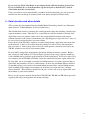
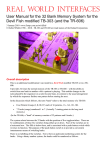
32 Bank Memory system: five toggleswitches and one pushbutton switch (the right toggleswitch is for a
different modification – Audio In to Filter), for the TB-303 Devil Fish, with the additional modifications
for Dynamic Bank/Channel Switching: Two 3.5mm sockets for Audio/CV inputs and two red LEDs to
indicate the sockets’ detector circuits being activated and so inverting the address bits generated by the two
left-most toggleswitches.
Contents
1 - Overall description..................................................................................................5
2 - Use in Pattern Play Mode .......................................................................................7
3 - Use in Track Play Mode ..........................................................................................8
4 - Data retention and other details ............................................................................9
5 - Dynamic Bank/Channel Switching (DBCS) .........................................................10
5.0 - Additional hardware................................................................................................ 10
5.1 - Block diagram without MIDI In and Out .................................................................. 12
5.2 - Block diagram with MIDI In and Out ....................................................................... 12
6 - Document history..................................................................................................13
0 - Combinations of features for the TR-606, TR-808 and TB-303
This is an additional modification I can install in a Devil Fish modified TB-303 or in a TR606. A similar system can be installed in the TR-808, with the switches aligned vertically on
the left side of the machine, with their toggles moving left-to-right.
This manual describes the Dynamic Bank/Channel Switching variants of the 32 Bank
Memory System, which I started installing in February 2014. Please see the Devil Fish page
for a separate manual describing the basic 32 Bank Memory System as I have been
installing it since April 1999. From the early 1980s I also installed memory systems with
4, 16, 21 or 32 banks, with completely different controls.
In the context of the TB-303 Devil Fish and the modified TR-606 and TR-808, the term
“Dynamic Bank/Channel Switching (DBCS)” refers to several combinations of
modifications, as explained in the following paragraphs and table.
For the TR-606 it refers to “Dynamic Bank Switching” in which two input sockets, two
approximately +1.15 volt detector circuits with two LEDs are used to potentially invert two
of the five memory bank address bits generated by the toggleswitches and pushbutton. The
input sockets, LEDs and switches look much the same as those in the picture above, which is
for the TB-303.
For the TR-808 it refers to “Dynamic Bank Switching” in which two or four input sockets,
two or four approximately +1.15 volt detector circuits (with two or four LEDs) are used to
potentially invert two or four of the five address bits generated by the toggleswitches and
pushbutton.
For the TB-303 Devil Fish without the MIDI In and Out system, the same is true as of
the TR-606: the term refers to “Dynamic Bank Switching” in which two input sockets, two
approximately +1.15 volt detector circuits (with two LEDs) are used to potentially invert two
of the five memory bank address bits generated by the toggleswitches and pushbutton. This
is true for the TB-303 Devil Fish with or without MIDI In. Only the MIDI In and Out
system supports Dynamic Bank/Channel Switching – which includes the ability to
dynamically switch MIDI In channels for Notes.
For the TB-303 Devil Fish WITH the MIDI In and Out system, the term refers to
“Dynamic Bank and MIDI In Channel Switching” in which two input sockets, two
approximately +1.15 volt detector circuits (with two LEDs) are used to potentially invert two
of the five memory bank address bits generated by the toggleswitches and pushbutton. The
potentially inverted bits from these switches are also used by the MIDI In and Out system to
switch between four contiguous MIDI In channels for reception of Notes. In addition, the
two input sockets can have their default contacts (which drive the output of the socket if
nothing is plugged into it) with bits which result from MIDI In (on Channel 15 or 16) Note
and/or Control Change messages. This means that in addition to using the toggleswitches to
control memory bank or MIDI In Channel, and the potential use of one or both Audio/CV
Input sockets to invert two of the bits, it is possible, when not using one or both of these
input sockets, to have the detector circuits and their LEDs and bit inversion circuits driven
by bits derived from MIDI In Note and/or Control Change messages received on Channel 15
or 16. This is the complete Dynamic Bank/Channel System – and all the MIDI aspects of it
are described in the MIDI In and Out System User Manual.
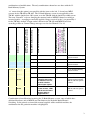
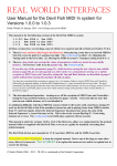
On the next page is a table of the possible scenarios involving a 32 Bank Memory system,
with an indication of whether the manual you are reading now, or some other manual, is the
best source of information. The “Installation” numbers “TB-303-x” refer to various
2
combinations of modifications. The only combinations shown here are those with the 32
Bank Memory System.
“na” means that this option is not possible with the items to the left. I do not have MIDI
systems for the TR-606 or TR-808. The 32 Bank Memory system is not applicable to the
TB-303 with the Quicksilver-303 system, or to the TR-606 with the Quicksilver-606 system.
The term “Dynamic” refers to changing the memory bank or MIDI In channel according to
external signals – according to externally applied voltages received by the 2 (or potentially 4
for the TR-808) Audio/CV Input sockets and/or for the TB-303 with MIDI In and Out,
according to Note or Control Change messages received on Channel 15 or 16.
Installation
MIDI In & Out?
Audio/CV Input sockets & LEDs for
Memory bank address bit inversion
Dynamic Memory Bank switching
Dynamic MIDI In Channel switching
MIDI In Notes and/or Control
Changes can drive the default pins
of the two 3.5mm Audio / CV input
sockets, to drive the detector and
inverter circuits if nothing is plugged
into these sockets.
User Manual
TR-606-0
na
No
No
na
na
Basic 32 Bank Memory
System manual.
TR-606-1
na
2
Yes
na
na
This manual.
TR-808-0
na
No
No
na
na
Basic 32 Bank Memory
System manual.
TR-808-1
na
2 or 4
Yes
na
na
This manual.
TB-303-1
None or
MIDI In
No
No
No
No
Basic 32 Bank Memory
System manual.
TB-303-2
None or
MIDI In
2
Yes
No
No
This manual.
TB-303-5
MIDI In
& Out
No
No
Yes – via Note &
Controller messages
via Channel 15 or 16,
not with switches
and/or input signals.
No
Basic 32 Bank Memory
System manual and the
MIDI In and Out System
manual.
TB-303-6
MIDI In
& Out
2
Yes
Yes – via the two
3.5mm sockets, LEDs
and the two left-most
Memory address
toggleswitches.
Yes
This manual and the
MIDI In and Out System
manual.
Combinations of modifications involving the 32 Bank Memory system, some of which have
additional hardware and or MIDI In and Out firmware for Dynamic Bank/Channel
Switching. In the printed version of this manual supplied with a modified machine, the
combination for this particular machine is highlighted.
3
All types of installation with the Audio/CV Input sockets, detector circuits and LEDs (TRcan be equipped with an optional Enable/Disable
Toggleswitch which enables both inversion circuits if it is in the up or down position. The
centre position disables the inversion circuits. On the TB-303 Devil Fish and TR-606, this
switch is located to the upper right of the Tempo knob. The photo at the start of this manual
shows a centre-off Audio In to Filter switch in this location. If both switches are required,
they are mounted side by side in approximately this location.
606-1, TR-808-1, TB-303-2 and TB-303-6)
The down position (Enable) is momentary – the toggle spring-returns to centre (Disable).
When this is switch is in the centre position, the detector circuits cannot be activated, so the
LEDs do not turn on and there can be no inversion of memory bank address bits (or for TB303-6, inversion of the bits from the two switches which will be used both for memory bank
address, and potentially for MIDI In Channel switching)
4
1 - Overall description
The 32 Bank Memory system provides 32 times the normal memory of the TB-303 (or TR606 or TR-808). This can be used for storing more patterns and tracks, but its most
important capability is that the Internal Sequencer, while playing a pattern, can be switched
instantly to another memory bank, by the manual manipulation of five toggleswitches and a
pushbutton switch. Since the Internal Sequencer reads note information from memory in the
microseconds before it plays each note, this means that manual operation of these switches
can cause the Internal Sequencer to play notes from different patterns, in the middle of a
pattern. This is much more musically fruitful than the unmodified instrument’s existing
capability, in Pattern Play mode, of switching from one pattern to another, with the new
pattern starting when the current pattern ends.
From February 2014, I am able to install a variant of this 32 Bank system which enables
Dynamic Bank/Channel Switching. This involves the potential inversion of address bits 3
and 2 (as described below) by detector circuits, with approximately +1.15 volt thresholds,
working from two Audio or CV input signals which arrive in two 3.5mm sockets on the
left side of the machine. If each of these detector circuits is activated, the associated LED is
turned on and the address bit which is normally produced by the associated switch is
inverted.
For the TR-606 and TR-808 the same applies, but for the TR-808 I can install four input
sockets, detector circuits, LEDs and address inversion circuits, which will potentially invert
address bits 3, 2, 1 and 0. For simplicity, most of the following explanation assumes a twochannel system for the TB-303, TR-606 or TR-808, applying to bits 3 and 2.
These input sockets, detector circuits, LEDs and address bit inversion circuits are described
fully in Section 5.
This manual is primarily for the TB-303 the Devil Fish mods, with notes about the TR-606
and TR-808 in brackets. (The 32 Bank Memory system, with or without Dynamic Bank
Switching, is independent of the Devil Fish mods, so I could install them in a TB-303
without the Devil Fish mods. So far, everyone who wanted this system wanted it installed
with the Devil Fish mods.)
The 32 Bank Memory system provides 32 times the normal memory of the TB-303, TR-606
or TR-808 – with the ability to switch from one bank to another while a pattern is playing by
operating toggleswitches and/or a pushbutton switch. This enables changes to the notes
played by the Internal Sequencer on a note-by-note basis, in the middle of a pattern, in
contrast to the usual arrangement by which the Internal Sequencer finishes one pattern
before starting the next.
In the discussion which follows, the term "bank" refers to the total memory of a TB-303:
•
Four Pattern Groups (I, II, III, IV) each of 16 patterns, 1A - 8A, 1B - 8B. This is a
total of 64 patterns.
•
7 Tracks (songs) numbered 1 to 7. (Actually 7 starting points in the long track
memory.)
(In the TR-606, a "bank" of memory consists of 32 patterns of up to 16 beats – and 8 tracks.
The TR-808 has 16 patterns and 12 tracks. Each TR-808 pattern has an A and a B section,
with each section being initially 16 beats long in its first part and 0 beats long in its second
part, with the total length of the two parts being 1 to 32 beats.)
5
The system selects between the 32 banks with the position of five toggleswitches. There are
32 combinations of these five switches being either up or down. Four of the switches are in
a horizontal row. The fifth is below them, and is associated with a pushbutton switch which
reverses its function. The purpose of the pushbutton switch is to provide a convenient and
instantaneous means of switching banks.
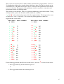
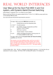
The switches are not labelled. There is no particular numbering system for the banks. Using
a binary number system, the 32 banks could be numbered as follows.
'▼' and '▲' refer to down and up states of the five toggleswitches. We interpret these states
as binary bits 0 and 1 respectively. For instance the photograph above shows the
toggleswitches set for bank 1.
Switches
4 3210
Bank number
▼ ▼▼▼▼
▼ ▼▼▼▲
0
▼ ▼▼▲▼
▼ ▼▼▲▲
2
▼ ▼▲▼▼
▼ ▼▲▼▲
4
▼ ▼▲▲▼
▼ ▼▲▲▲
6
▼ ▲▼▼▼
▼ ▲▼▼▲
8
▼ ▲▼▲▼
▼ ▲▼▲▲
10
▼ ▲▲▼▼
▼ ▲▲▼▲
12
▼ ▲▲▲▼
▼ ▲▲▲▲
14
1
3
5
7
9
11
13
15
Switches Bank number
4 3210
▲ ▼▼▼▼
▲ ▼▼▼▲
16
▲ ▼▼▲▼
▲ ▼▼▲▲
18
▲ ▼▲▼▼
▲ ▼▲▼▲
20
▲ ▼▲▲▼
▲ ▼▲▲▲
22
▲ ▲▼▼▼
▲ ▲▼▼▲
24
▲ ▲▼▲▼
▲ ▲▼▲▲
26
▲ ▲▲▼▼
▲ ▲▲▼▲
28
▲ ▲▲▲▼
▲ ▲▲▲▲
30
17
19
21
23
25
27
29
31
For the fifth toggleswitch (labelled 4 in the table above), the state '▲' is achieved with either:
1 - The toggleswitch up and the button not pressed.
or
2 - The toggleswitch down and the button pressed.
6
2 - Use in Pattern Play Mode
(This section and the next do not mention Dynamic Bank/Channel Switching, which is an
elaboration upon the basic 32 Bank Memory system described here.)
If there is no need to switch banks while a pattern is playing, then operation is
straightforward. Simply select the desired memory bank with the toggleswitches and use the
machine normally.
Switching banks while the sequencer is playing patterns enables the creation in real-time of
novel combinations of notes. For instance the first half of a pattern in Bank 8:
▼ ▲▼▼▼ 8
could be played, and then by moving the right switch to the up position, the rest of the notes
in that bar of music will come from a pattern in Bank 9:
▼ ▲▼▼▲ 9
Each pattern contains the following information:
•
The length of the pattern in steps. This can be between 1 and 16, or 1 to 15 for triplet
mode. After clearing the pattern, hold down the Function button and press the "Step"
button "9" (the same as Transpose Down) once for each note you want in the pattern.
•
The "pre-scale", which is typically for 16 notes per 96 clock bar, but can be in triplet
mode for 12 notes per 96 clock bar. After clearing the pattern, it is in 1/16th note
mode, but by holding Function and pressing "0" the pattern is forever set to triplet
mode.
•
16 notes, each of which contains:
o
o
o
Pitch.
Accent on/off.
Slide on/off.
(For the TR-606, each pattern has 1 to 16 beats, each of which can have each drum sound
and accent programmed on or off. Likewise the TR-808, where the A part or the B section
of a pattern can have 1 to 16 beats in its 1st part and 0 to 16 beats in its 2nd part.)
The Internal Sequencer is a single-chip microcontroller (for convenience referred to here as
the “CPU”) connected to what is normally a single bank of memory. With the 32 bank
modification, there are actually 32 banks of memory, and the CPU accesses whichever bank
is currently selected by the toggleswitches and pushbutton. (The switches are de-bounced, so
there are no messy transitions between banks due to mechanical bouncing of switch
contacts.)
When the machine starts playing a pattern, the Internal Sequencer firmware (which is
permanently built into the CPU) reads the length and pre-scale and stores these values in the
CPU's internal RAM. When it comes to play each note (for the TR-606 and TR-808, each
beat), the Internal Sequencer firmware causes the CPU to reads the external memory to
retrieve the note, Accent and Slide information for that note. (For the TR-606 and TR-808,
the CPU reads which drums are to be triggered, and whether Accent is to be set from
external memory just before playing each beat.)
Therefore, by using the five toggleswitches and/or the pushbutton switch to select another
bank of memory in the middle of a pattern, the Internal Sequencer will play subsequent notes
7
from the new memory bank. Switching will not change the note currently being played, but
affects all subsequent notes.
Here is a concrete example for the TB-303. The memory switches are set to:
▲ ▼▼▲▼ Bank 18
The Internal Sequencer is started and is playing Pattern 5B in Pattern Group III. Let's call
this "Pattern III-5B". The Internal Sequencer plays this pattern several times and then in the
middle of the pattern, while note 4 is playing, either the fifth toggleswitch ("4" in the above
chart) is lowered, or the pushbutton is pressed. Either action has the same effect of making
the fifth switch function (address bit 4) as a "low". So the bank select address bits are now
▼ ▼▼▲▼ Bank 2
As the CPU prepares to play the fifth note, it reads from memory, but instead of reading
Note 5 of Bank 18's Pattern III-5B, it reads Note 5 of Bank 2's Pattern III-5B. So the pitch,
Accent and Slide will vary as the banks are switched, but the CPU will take no notice of the
lengths and pre-scales of Bank 2's Pattern III-5B.
Switching banks whilst in Pattern Write, Track Write or Track Play modes will surely lead
to confusion of both the Internal Sequencer firmware and the user!
3 - Use in Track Play Mode
(This section does not mention Dynamic Bank/Channel Switching, which is an elaboration
upon the basic 32 Bank Memory system described here.)
When I first began modifying TB-303s, TR-606s and TR-808s in 1981/82 , it was to install
multiple memory banks. The purpose was to store more patterns and tracks so the users
could use the machines to accompany them on guitar, vocals, keyboards etc. Some of these
musicians had repertoires of hundreds of songs. In those systems I used pushbutton
switches, counters LEDs and/or 7 segment figure-8 LED displays to control and display the
current bank number. These memory systems were designed to reset the CPU whenever the
bank was changed. Therefore changing from bank 23 to bank 13 was like turning off one
drum-machine or TB-303 and turning on another. This was necessary, since there were
certain items of data in the Track memory which was only read when the CPU ran its
initialisation routines after being reset. (In the case of the TR-808, I made this reset circuit
disableable to allow for live switching between banks in Pattern Play mode.)
Without this automatic reset circuit, there was a grave danger of the user changing banks
whilst the CPU was running, and so causing it to become confused – particularly in regard to
the starting and ending points of tracks and the prescales and lengths of patterns.
Now that the primary use of the TB-303 / Devil Fish (and the TR-606 and TR-808) is realtime manipulation rather than playing songs reliably, I have changed the memory control
system. The new system has no automatic reset circuitry at all.
This toggleswitch and pushbutton arrangement is simple, flexible and reliable. However, if
you are using Track Play mode and you switch banks whilst the machine is turned on, then it
is quite likely that the CPU's firmware will generate unexpected and undesirable results.
8
If you are using Track Play Mode, do not change banks while the machine is turned on.
If you accidentally do so, turn the machine off and on again so that the CPU reads in
crucial data from the current bank.
Unless you want to create unpredictable scrambles in the track memory, be sure to turn the
machine on and not change its memory bank at all, before using Track Write mode!
4 - Data retention and other details
(This section does not mention Dynamic Bank/Channel Switching, which is an elaboration
upon the basic 32 Bank Memory system described here.)
This modification involves removing the existing memory chips and installing a much larger
capacity memory system. Therefore it is not possible to retain the machine's memory data.
Apart from a few test patterns I write into it, the newly modified machine will contain
random data (the result of how each memory cell’s flip-flop powers up in the 0 or 1 state), so
be sure to clear each track before you start writing.
I have observed the TB-303's sequencer do some strange things, apparently with errant data
in the memory. I don't recall exactly what these things are, how to create the situation or
how to resolve it. Such strange states of data in certain patterns cannot be ruled out in any
TB-303, whether or not it has extra memory banks.
In early 2015 I changed the arrangements for battery backup of memory systems. Before
this, starting in 1996 with the V2.x Devil Fishes, I always used a large capacity cylindrical
1/2AA lithium battery soldered to the main Devil Fish circuit board. In all cases where I did
extra memory for the TR-606 or TR-808, I used the same kind of battery, again soldered in.
In early 2015, due to air-freight restrictions on lithium batteries, it became apparent that we
could only ship machines overseas, with insurance, if there was no lithium battery installed.
So machines going overseas have an internal lithium battery holder, and no lithium battery,
while machines being shipped to customers in Australia go by road and have a lithium
battery installed. These batteries should last 10 years at least, and are user-replaceable, once
the machine is partly disassembled.
Please see the separate manuals for the Devil Fish TB-303, TR-606 and TR-808 respectively
regarding the battery arrangements for memory backup.
9
5 - Dynamic Bank/Channel Switching (DBCS)
5.0 - Additional hardware
The additional hardware which enables Dynamic Bank/Channel Switching consists of:
1-
Two 3.5mm mono Audio/CV Input sockets on the left side of the machine.
2 -
Two approximately +1.15 volt detector circuits, which are described below.
3-
Two Red LEDs, which are On when the corresponding detector circuit is
activated.
4-
Two Address Bit Inversion Circuits. Each has two inputs: the 0 or 1 output of a
memory bank address switch, and the output of corresponding detector circuit.
The output is the XOR (Exclusive OR) of the two inputs, as described below.
The output drives the corresponding bank address bit of the memory system.
This description is for the TB-303 Devil Fish, the TR-606 and the two channel version of the
DBCS mods for the TR-808. It is also possible to install a four channel version for the TR808.
For the TB-303 Devil Fish with the MIDI In and Out system, there are two additional
hardware functions, neither of which are visible:
1-
The MIDI In and Out firmware can drive the “default contact” (AKA “normally
closed contact”) of each of the two Audio/CV sockets. This enables the firmware
to drive the output of the socket, which goes to the detector circuit, if nothing is
plugged into the socket. (If a lead is only partially inserted, sufficient to touch the
contact, but not to lift it off the default contact, then unless the lead has a strong
load or signal, the signal created by the firmware will still drive the output of the
socket, and it will drive the lead as well.)
2-
The MIDI In and Out firmware can read the output of the Address Bit Inversion
Circuits – the same two bits which are driving memory bank address bits 3 and 2.
These bits can be used to change the MIDI In Channel for receiving Notes, so that
instead of receiving only on the currently selected MIDI In channel, Notes can be
received on this channel, this channel plus 1, this channel plus 2 or this channel
plus 3, with wraparound of 17, 18 and 19 to 1, 2 and 3 respectively.
Each detector circuit senses its input voltage going above approximately +1.15 volts.
The exact threshold voltage will be between 1.05 volts and 1.25 volts, with these extremes
only likely to be reached in very hot or cold conditions respectively. This voltage is chosen
so it can be reliably turned off with a 1.0 volt signal from a MIDI to CV converter. The TB303 (including the Devil Fish) produces 1.0 volts from its CV out socket, when playing the
lowest C of the Internal Sequencer’s range.
This threshold and its +/- 10 millivolt tolerance means that the input can be reliably turned
on with 1.25 volts, which a MIDI to CV converter can produce in response to a note event 3
semitones above that which produces the 1.0 volts. The TB-303 (including the Devil Fish)
produces this voltage from its CV Out socket when it is playing the D# in the lowest octave
of the Internal Sequencer’s range. Each semitone is represented by 1/12 of a volt = 0.08333
volts.
10
This approximately 1.15 volt threshold can also be activated by reasonably high level audio
signals.
Within a fraction of a millisecond of the input voltage going above the threshold, the
detector is activated and remains activated for about 33 msec. This means even a narrow
positive pulse waveform which reaches about +1.15 volts will turn the detector on
continually, as long as its frequency is above about 30Hz. The input can handle +/- 15 volts.
There’s no problem feeding these inputs with a continually high +15 volt CV, or any audio
or CV in this range. (It is probably fine to go to +/- 30 volts or so, but +/- 15V is the range
of most modular gear, and of line level signals in studios.)
Audio signals whose positive peaks extend to +1.15 volts are commonly found in studios
when the volume setting is maximised. Microphones and electric guitars generate smaller
signals, but some sythesizers can generate signals of this magnitude. The TB-303, Devil
Fish and TT-303 Bass Bot generally do not create signals with positive peaks in excess of
+1.15 volts, so it will often be necessary to send audio signals through a pre-amp, effects
box or a mixer channel in order to activate these detector circuits.
One or two audio or CV signals can be used to dynamically alter the memory bank the
Internal Sequencer is playing from. “Dynamic” in this context means as a result of external
audio or CV signals, not just as a result of manual actions on the toggleswitches. With the
MIDI In and Out system, if nothing is plugged into an Audio/CV Input socket, the MIDI In
and Out firmware can drive the output of the socket, and so the detector circuit, LED and
address bit inversion circuit, according to Note and/or Control Change messages received on
MIDI In Channel 15 or 16. This enables dynamic switching of both the memory bank and, if
enabled, the MIDI In channel for Notes. “Dynamic” in this context refers to the reception of
external MIDI In Note and/or Control Change messages.
Address bit inversion follows Exclusive Or (XOR) logic. Inclusive OR means “the output
is high if one or more of the inputs are high”. “High” generally means a binary 1 while
“low” generally means binary 0. XOR gates have only two inputs. The output is high when
one or the other input is high, but not when both are high. The truth table is:
Input bits
0
0
1
1
0
1
0
1
Output bit
0
1
1
0
11
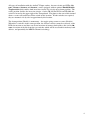
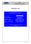
5.1 - Block diagram without MIDI In and Out
Below is a diagram depicting the signals an circuit elements for the two channel Dynamic
Bank Switching system. This diagram represents the circuitry of the TB-303 Devil Fish with
the 32 Bank Memory system and the DBCS additional hardware, but without the MIDI In
and Out system. This diagram also represents the circuitry of the TR-606 or TR-808 with 32
Bank Memory systems and two channel DBCS hardware.
The TR-808 can have four channels of DBCS hardware, so this diagram applies for bits 3
and 4 (as for the TB-303 and TR-606) and also for address bits 1 and 0.
1.15 volt
Rear (right) 3.5mm
\
/-->-DETECTOR--\-------> Right
Audio/CV
\ /
Right
|
LED
Input Socket Ext sig. ===================> \/
|
Affects bit 3.
v
|
|
1.15 volt
|
Front (left) 3.5mm
\
/-->-DETECTOR--\------------> Left
Audio/CV
\ /
Left
|
|
LED
Input Socket Ext sig. =========> \/
|
v
Affects bit 2.
v
|
|
|
Right Toggleswitch ---->------------------>--\ |
Affects bit 2.
|
| |
|
XOR
Left Toggleswitch --->------------------>---\ |
|
Affects bit 3.
| |
|
XOR
|
|
|
|
|
Address bits to the 32 bank
v
v
memory system
Bit 3
Bit 2
If nothing is plugged into the two Audio/CV Input sockets, then the detector circuits will be
Off, the Red LEDs will be Off and the address bit inversion circuits (the XOR gates) will not
invert the input they receive from the toggleswitches. So if the toggleswitch is down, the bit
which forms part of the memory bank address will be 0, as it is for the other toggleswitches
for bits 4, 1 and 0 (assuming the pushbutton is not pressed, since this inverts bit 4).
If an input signal activates the detector circuit, the corresponding LED will be On and the
address bit will be inverted. So if the toggleswitch is down, the bit which forms part of the
memory bank address will be 1.
5.2 - Block diagram with MIDI In and Out
Please refer to the diagram in the section Data flow for Installation 6 in the Devil Fish MIDI
In and Out system User Manual. This is similar to the diagram above, with the addition of
the MIDI In and Out firmware driving the default contacts of the two sockets, and sensing
the potentially inverted bits 3 and 2 of the memory bank address.
12
6 - Document history
2014-02-15 Forked the 32 Bank Memory system User Manual to create this manual.
2014-07-29 Loosened the specification for the threshold from “1.1 volts” to
“approximately 1.15 volts – and between 1.05 and 1.25 volts”.
2015-02-07 New battery arrangements for memory, so referred to the separate manual for
these.
13