1
Gauger420
User Manual
You Can Measure the Solid Benefits…
Notices and safety guidelines
This manual is delivered subject to the following conditions and restrictions:
•
•
•
•
•
•
•
•
•
The manual contains proprietary information belonging to Solid Applied Technologies Ltd. The
information is published solely for the purpose of assisting authorized users of Gauger420.
No part of this manual may be used for any other purpose, or disclosed to any person or firm, or
reproduced by any means, without the prior written permission of Solid Applied Technologies Ltd.
The text and graphics in this manual are for the purpose of illustration and reference only.
Information included in this manual is subject to change without notice. Information in the manual
may contain inaccuracies. Specifications are based on laboratory test results which are performed
under tightly controlled environment. Field performance may vary from laboratory test results. We
always welcome suggestions and recommendations from the users of our manuals.
All company names, brand products and service names that may appear in this manual are
trademarks or registered trademarks of their respective holders.
Solid Applied Technologies shall not be liable for any loss or damage caused by the use of this
manual or of products described in the manual. Solid Applied Technologies sole warranty is that
products sold by the company shall be free of defects in material and in workmanship for a period of
12 months.
Gauger420 must be installed, connected and operated in accordance with the instructions of this
manual and with the Gauger420 certifications. Specific local regulations may also apply.
Do not open or disassemble Gauger420 except as required for electrical connections.
Any type of modifications and repairs are permissible only upon the manufacturer or re-seller
written approval and by pre-qualified personal. Never reuse defective parts.
Date
Jan 2012
Revision
1.12
Software version
Gauger420 3.12
Part number
Gauger420
_____________________________________________________________________________________
Gauger420 – User Manual
page 2 of 69
Jan 2012 Rev 1.12
Table of Contents
NOTICES AND SAFETY GUIDELINES......................................................................................................................... 2
TABLE OF CONTENTS.............................................................................................................................................. 3
LIST OF FIGURES..................................................................................................................................................... 6
I. INTRODUCTION .................................................................................................................................................. 7
1. DESCRIPTION .............................................................................................................................................................7
2. GAUGER420 PARTS ....................................................................................................................................................8
3. DIMENSIONS .............................................................................................................................................................9
4. SPECIFICATIONS........................................................................................................................................................ 10
5. HOW TO USE THIS USER MANUAL .......................................................................................................................13
II. PHYSICAL AND ELECTRICAL INSTALLATION GUIDELINES ................................................................................... 14
1. GEOMETRICAL CONSIDERATIONS..................................................................................................................................14
2. TANK FITTING ..........................................................................................................................................................15
3. DEAD ZONE .............................................................................................................................................................16
4. EXTENSION PIPE ....................................................................................................................................................... 16
5. TEMPERATURE CONSIDERATIONS AND TEMPERATURE SENSORS ..........................................................................................17
6. ELECTRICAL SCHEMATICS AND POWER SUPPLY ................................................................................................................18
7. ELECTRICAL CONNECTIONS..........................................................................................................................................19
8. MUST BE PAMPHLET ...............................................................................................................................................21
III. KEYPAD AND DISPLAY ..................................................................................................................................... 22
1. KEYPAD ..................................................................................................................................................................22
1.1 Navigation keys .............................................................................................................................................22
1.2 Execution keys ...............................................................................................................................................22
2. NAVIGATION THROUGH MENUS ...................................................................................................................................23
2.1 Sub-Menu style..............................................................................................................................................23
2.2 Numeric menu style ......................................................................................................................................23
3. MEASUREMENT SCREEN.............................................................................................................................................24
3.1 Status reports ................................................................................................................................................24
3.2 Contrast.........................................................................................................................................................24
3.3 Main menu / setup ........................................................................................................................................25
3.4 Temperature readings ...................................................................................................................................25
3.5 Ultrasonic echo conditions ............................................................................................................................25
3.6 Product identification details ........................................................................................................................25
IV. CONFIGURATION WITH THE KEYPAD AND DISPLAY ........................................................................................ 26
1. MENU AND SUB-MENU ORGANIZATION .........................................................................................................................26
2. QUICK SETUP...........................................................................................................................................................27
3. ADVANCED SETTINGS.................................................................................................................................................28
4. SETTINGS AVAILABLE IN PC CONFIGURATION ONLY ..........................................................................................................29
_____________________________________________________________________________________
Gauger420 – User Manual
page 3 of 69
Jan 2012 Rev 1.12
V. CONFIGURATION WITH A PC............................................................................................................................ 30
1. INTRODUCTION ........................................................................................................................................................ 30
2. PREPARING A CONFIGURATION TEXT FILE .......................................................................................................................30
2.1 Sample files ...................................................................................................................................................30
2.2 Multi Value commands ................................................................................................................................. 31
3. DOWNLOAD OPERATION ............................................................................................................................................32
3.1 Procedure ......................................................................................................................................................32
3.2 Launching and setting up HyperTerminal .....................................................................................................32
3.3 Downloading a configuration file..................................................................................................................35
4. RESPONSES FROM GAUGER420 ..................................................................................................................................35
4.1 Good response ..............................................................................................................................................35
4.2 Erroneous responses .....................................................................................................................................36
4.3 Communication Errors ..................................................................................................................................37
5. LIST OF COMMANDS FOR CONFIGURATION FROM A PC .....................................................................................................37
5.1 Conventions...................................................................................................................................................37
5.2 List for Metric unit system.............................................................................................................................39
5.3 List for American unit system ........................................................................................................................41
5.4 Notes .............................................................................................................................................................46
6. SOME USEFUL EXAMPLES............................................................................................................................................47
6.1 Basic setup ....................................................................................................................................................47
6.2 Advanced setup .............................................................................................................................................47
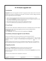
VI. FIRMWARE UPGRADE TOOL ........................................................................................................................... 48
1. INTRODUCTION ........................................................................................................................................................ 48
2. YOU WILL NEED ........................................................................................................................................................ 48
3. INSTALLATION OF FIRMWARE UPGRADE TOOL AND USB DRIVER ........................................................................................48
4. UPGRADE PROCEDURE ...............................................................................................................................................48
5. TROUBLESHOOTING THE FIRMWARE UPGRADE PROCESS ...................................................................................................50
VII. SERIAL DATA MONITORING ........................................................................................................................... 51
VIII. USB DRIVER INSTALLATION ON A PC ............................................................................................................ 52
IX. REFERENCE GUIDE .......................................................................................................................................... 55
APPLICATION DIMENSIONS AND CONSTRAINTS....................................................................................................................55
(a) Basic dimensions............................................................................................................................................55
(b) Distance to empty level .................................................................................................................................56
(c)Distance to full level ........................................................................................................................................56
(d) Far blocking distance .....................................................................................................................................56
(e) Near blocking distance...................................................................................................................................57
APPLICATION TYPE ........................................................................................................................................................ 57
DEFAULT VALUES..........................................................................................................................................................57
DISTANCE UNITS AND VALUE TO DISPLAY ...........................................................................................................................58
FALSE ECHO SCAN ............................................................................................................. ERROR! BOOKMARK NOT DEFINED.
FILLING RATE...............................................................................................................................................................59
HART COMMUNICATIONS .............................................................................................................................................59
_____________________________________________________________________________________
Gauger420 – User Manual
page 4 of 69
Jan 2012 Rev 1.12
INTERDEPENDENCIES .....................................................................................................................................................60
RESET AND OPERATING HOURS ........................................................................................................................................62
TEMPERATURE SENSORS, UNITS AND DISPLAY .....................................................................................................................62
VOLUME MEASUREMENT ...............................................................................................................................................63
(a) General ..........................................................................................................................................................63
(b) Box shaped ....................................................................................................................................................63
(c) Cylindrical tanks .............................................................................................................................................64
4-20 COMMUNICATIONS ...............................................................................................................................................66
(a) 4-20 Setup ......................................................................................................................................................66
(b) 4-20 Performance ..........................................................................................................................................67
(c) 4-20 constraints .............................................................................................................................................67
(d) 4-20 default settings ......................................................................................................................................67
_____________________________________________________________________________________
Gauger420 – User Manual
page 5 of 69
Jan 2012 Rev 1.12
List of Figures
Figure 1 – Gauger420 parts........................................................................................................................... 8
Figure 2 – Gauger420 dimensions for 75 KHz version .................................................................................. 9
Figure 3 – Minimum horizontal gap ............................................................................................................ 14
Figure 4 - Silo (left) and liquid (right) examples .......................................................................................... 15
Figure 5 - Threaded flange (left) Thread-free flange (right) ....................................................................... 15
Figure 6 – Possible extension pipe settings ................................................................................................ 16
Figure 7 – Possible extension pipe fittings.................................................................................................. 17
Figure 8 - Power supply and ground schemes ............................................................................................ 18
Figure 9 - Electrical ports ............................................................................................................................ 19
Figure 10 - Navigation keys ......................................................................................................................... 22
Figure 11 - Execution keys .......................................................................................................................... 22
Figure 12 - Sub menu screens ..................................................................................................................... 23
Figure 13 - Numeric menu .......................................................................................................................... 23
Figure 14 - Measurement screen ................................................................................................................ 24
Figure 15 - Temperature readings .............................................................................................................. 25
Figure 16 - Menu and submenu organization............................................................................................. 26
Figure 17 - False echo scan screen.............................................................................................................. 27
Figure 18 - Application dimensions (for 75 KHz sensor) ............................................................................. 55
Figure 19 - Temperature readings .............................................................................................................. 63
Figure 20 - Box shaped tank ........................................................................................................................ 63
Figure 21 - Cylindrical horizontal tank ........................................................................................................ 64
Figure 22 - Cylindrical vertical tank ............................................................................................................. 64
Figure 23 - Default 4-20 values for Level .................................................................................................... 67
Figure 24 - Default 4-20 values for Volume ................................................................................................ 68
Figure 25 - Default 4-20 values for Distance ............................................................................................... 68
_____________________________________________________________________________________
Gauger420 – User Manual
page 6 of 69
Jan 2012 Rev 1.12
I. Introduction
1. Description
Gauger420 is a mono-block, 2-wire, ultrasonic level meter with integrated 4-20 current loop and USB
interface for configuration and firmware upgrade. Optional items include display, HART protocol,
external temperature sensor, dry contact input and output.
Gauger420 measures distance. Targets may be liquid or solids. Measurement is continuous and does not
require contact with the target. The system can accurately measure steady or agitated target surfaces.
The system can also rapidly track filling and emptying of vessels. The system measurement distance
spans 15 cm to 8 meters. In addition to distance, Gauger420 also measures temperature of the
environment.
Gauger420 makes use of the measured distance to calculate additional variables of importance. These
variables include target level, target volume and optional Open Channel Flow.
Gauger420 operates at an ultrasonic frequency of 75KHZ (optional 50 KHz) and is robust in noisy
conditions. The sensor is made of PVDF – providing good chemical resistance to corrosive targets.
Gauger420 is fed from 24VDC power and may be fed by other sources as long as 18VDC is measured on
Gauger420 terminals. Measured data is reported over a 4-20mA current loop. Both 4mA and 20mA end
points may be set independently and may support both upward and downward trends. In addition, data
may be presented on a local display or transmitted over a HART protocol (optional).
Gauger420 is equipped with a large graphic display and keypad allowing a simple wizard-driven setup of
the system. The keypad and display allow configuration of many Gauger420 configuration parameters.
Complete setup of all Gauger420 parameters can be executed using a USB equipped PC or laptop. This
method of configuration supports rapid cloning of many Gauger420 systems. The setup is performed
outside the 4-20 loop.
This user manual is intended for users and operators of Gauger420. The manual covers system
description, installation, operation and troubleshooting of Gauger420.
_____________________________________________________________________________________
Gauger420 – User Manual
page 7 of 69
Jan 2012 Rev 1.12
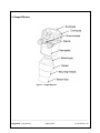
2. Gauger420 parts
Figure 1 – Gauger420 parts
_____________________________________________________________________________________
Gauger420 – User Manual
page 8 of 69
Jan 2012 Rev 1.12
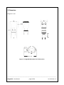
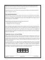
3. Dimensions
All figures in mm.
Figure 2 – Gauger420 dimensions for 75 KHz version
_____________________________________________________________________________________
Gauger420 – User Manual
page 9 of 69
Jan 2012 Rev 1.12
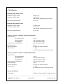
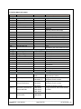
4. Specifications
Measuring range (75 KHz version)
Maximum range for liquids
Maximum range for Solids
-
Minimum range (dead zone)
-
Measuring range (50 KHz version)
Maximum range for liquids
Maximum range for Solids
-
Minimum range (dead zone)
-
8 meter / 26’
5 meter / 16’
Approximate, depending on type of solid
15 cm / 6”
9.5 meter / 30’
6 meter / 19’
Approximate, depending on type of solid
35 cm / 10”
Accuracy – precision – resolution –tracking (75 KHz version)
Display Accuracy
15cm<Range<60cm
1.5mm
60cm<Range<5m
0.3% of measured range
5m<Range<8m
0.2% of maximum range
Display Precision (repeatability)
0.2% of measured range
Display resolution
1 mm
Process tracking rate
10 meter per minute maximum
4-20 Accuracy
+/- 20μA
For process rates up to 5 meter per minute
Accuracy – precision – resolution –tracking (50 KHz version)
Display Accuracy
25cm<Range<60cm
1.5mm
60cm<Range<5m
0.3% of measured range
5m<Range<9.5m
0.25% of maximum range
Display Precision (repeatability)
0.3% of measured range
Display resolution
1 mm
Process tracking rate
10 meter per minute maximum
4-20 Accuracy
+/- 20μA
For process rates up to 5 meter per minute
Electrical specifications
Power supply
-
24VDC or minimum 18VDC on Gauger Terminals
_____________________________________________________________________________________
Gauger420 – User Manual
page 10 of 69
Jan 2012 Rev 1.12
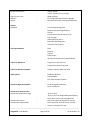
Current consumption
-
4.0mA – 20mA
3.6mA – 22mA for error settings
950Ω at 33VDC
For configuration and firmware upgrade
64X128 Graphic LCD, viewing size 50X25mm2
Loop current circuit
USB port
Display
-
Reports
Displayed
-
Level and percentage level
Distance and percentage distance
Volume
Temperature (internal and external)
Echo strength
Global operating hours
Resettable operating hours
Ultrasonic status reports
4-20 representation
-
Level
Distance
Volume
Fixed current
4mA and 20mA may be set independently
4-20 error indications
-
Target closer than Full level
Target further than Empty level
4-20 error indications options
-
3.6mA or 22mA or Hold Last Value
HART options
-
Enabled or disabled
Device address
Four measurement variables
System Configuration options
-
Via local keypad and display
By PC via USB port
Temperature characteristics
Operational temperature range
-
-20°C to +70°C
-30°C to +70°C for Gauger420 without display
Note: above +60°C accuracy depreciates
Temperature sensors
Internal and optional support for external
Temperature compensation
Built-in based on internal sensor, external
sensor or average of the two
_____________________________________________________________________________________
Gauger420 – User Manual
page 11 of 69
Jan 2012 Rev 1.12
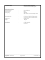
Temperature display
-
Internal and external temperature
Instantaneous and recorded high/low
-
Plastic PC/ABS+UV
PVDF
IP65/IP67
IP68 - 96 hours at 1.8 meter depth in water
Mounting threads
-
Cable entries
Weight
-
1.5” BSP or 1.5” NPT (for 75 KHz version)
2.0” BSP or 2.0” NPT (for 50 KHz version)
Conduit ½”NPT
960 gram
Certifications
-
Mechanical specifications
Enclosure material
Sensor material
Sealing rating
CE: EMC and Safety
FCC Part 15
_____________________________________________________________________________________
Gauger420 – User Manual
page 12 of 69
Jan 2012 Rev 1.12
5. HOW TO USE THIS USER MANUAL
At this stage…
First thing
If you are not familiar with
Level measurement terms
If you are ready to power up
the Gauger
If you want to quickly
configure the Gauger
If you want to know all about
Gauger configurations
If you are about to install in
the field
If you are unsure about any
term or concept
Do this…
Read the description section in this introduction chapter. Also
review the safety guidelines right at the beginning of this user
manual.
Review the section: Application dimensions and constraints in
the reference guide chapter.
Review the sections: electrical schematics and electrical
connections in the physical and electrical installation chapter.
Study the chapter: keypad and display. Then read the section
about quick setup in the chapter that follows.
Study the chapter: configuration with a PC while referring to the
reference guide chapter as required.
Carefully study the chapter: Physical and electrical installation
guidelines.
Consult with the reference guide chapter.
_____________________________________________________________________________________
Gauger420 – User Manual
page 13 of 69
Jan 2012 Rev 1.12
II. Physical and electrical installation guidelines
This chapter is a list of guidelines for proper physical installation of Gauger420 on tanks including
electrical connections. The final section is a short and concise list of instructions – the “must-be
pamphlet”. Always ensure that Gauger420 is installed in an area that meets the stated ratings of the
product including temperature and technical specifications
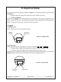
1. Geometrical considerations
•
•
•
•
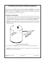
Gauger systems are installed above the target (e.g. water, fuel) being measured and should not
make contact with the target at any time. Typically, the systems are installed on top of a tank (filled
with liquid) through a hole on the roof of the tank. In outdoor applications, Gauger420 may be
attached to a metal arm extending above the target. The arm may be attached to a nearby post.
Gauger420 should be located as far as possible from vertical tank walls and from other physical
obstructions such as filling inlets. Keep a minimum gap of: 30 cm plus 10 cm for each meter of
measurement range.
Figure 3 – Minimum horizontal gap
For best results, place Gauger420 away from sources of acoustic noise or sources of vibrations.
Gauger420 should be perpendicular to the surface of a liquid target. The angular displacement
should be less than 5° from the vertical axis.
_____________________________________________________________________________________
Gauger420 – User Manual
page 14 of 69
Jan 2012 Rev 1.12
•
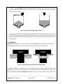
For solids in silos, Gauger420 should be aimed towards the center of the silo’s base. The sensor
should be displaced from the center of the tank and oriented perpendicular to the solids surface
when tank is at full state.
Figure 4 - Silo (left) and liquid (right) examples
•
Proper physical installation is accompanied by software setup. Setup includes defining parameters
such as tank height and may include additional parameters such as NBD, FBD, False echo scan and
more. For additional information read the section in the reference guide: “Application dimensions
and constraints”.
2. Tank fitting
Gauger420 is equipped with a 1.5”BSP / 1.5”NPT thread allowing two fitting options: direct fitting in a
threaded flange or fastened with a 1.5” BSP / 1.5” NPT nut through a thread-free flange.
Figure 5 - Threaded flange (left) Thread-free flange (right)
For outdoor installations, use a stable arm. Firmly attach the sensor to the arm using a through-hole and
threaded nut. Alternatively, attach the sensor to a threaded hole which is built-in the arm. Always verify
thread compatibility between Gauger420 and flange or nut. Do not use excessive force when using
_____________________________________________________________________________________
Gauger420 – User Manual
page 15 of 69
Jan 2012 Rev 1.12
threads. Preferably, tighten by hand only. If you do use a wrench, grip Gauger420 at the wrench grip
surfaces only (see figure Gauger420 parts) and exert light force.
3. Dead zone
See reference guide: “Application dimensions and constraints”.
A gap must be kept between the face of sensor and the topmost level of the target. This gap must be at
least the size of the specified “dead zone”. If the target level passes the dead zone, measurements may
be unpredictable. Therefore, it is recommended to keep a margin gap between the expected topmost
level and the dead zone border. Where the topmost level is too close to the tank roof, an extension pipe
is required for the installation as described below.
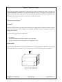
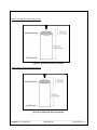
4. Extension pipe
See reference guide: “Application dimensions and constraints”.
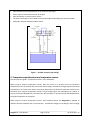
An extension pipe is required for installations where the topmost target level is too close to the roof of
the tank. In such cases, an extension pipe is installed on the tank and the sensor is installed on top of the
extension pipe at a safe distance from the topmost level of the target. The lower border of the dead
zone may fall inside the tank as seen in the right hand side of the figure below. In this case no further
software settings are required. The lower border of the dead zone may also fall within the extension
pipe as described in the left hand side of the figure blow. In such cases, the Near Blocking Distance
(NBD) should be configured in the software.
Figure 6 – Possible extension pipe settings
A typical structure of an extension pipe is shown on the next figure. Closely follow these guidelines
when using an extension pipe:
• Internal pipe diameter should be at least 3” wide
• The diameter of the hole on the flange or tank should not be smaller than the pipe diameter
• Pipe length (measured from sensor face) should be no longer than 50 cm
• The pipe should not protrude into the tank
_____________________________________________________________________________________
Gauger420 – User Manual
page 16 of 69
Jan 2012 Rev 1.12
•
•
•
•
•
Pipe should be exactly perpendicular to the surface of the target
Sensor must be located at the center of the pipe
Pipe should have a smooth interior surface
The hole in the flange or tank should have a smooth edge and welding spots must be avoided
Preferably, the pipe should be made of plastic
Figure 7 – Possible extension pipe fittings
5. Temperature considerations and temperature sensors
See also reference guide: “Temperature sensors, units and display”.
When using an external temperature sensor, place the sensor at a location that best represents
temperature of the air between the sensor face and the target. Avoid direct sunlight exposure and keep
covered from rain. Connect the sensor internally as described in the electrical connection section to the
Thermistor pins. External temperature sensors may be ordered from the manufacturer or reseller or
may be purchased independently. Use Thermistor NTC 10K Ohm 5% (minimum) P/N 2381-640-63103 by
Vishay BC Components or equivalent.
When using the internal temperature sensor, avoid situations where the Gauger420 is exposed to
different thermal conditions than its environment. Avoid direct sunlight on the Gauger. Direct sunlight
______________________________________________________________________________
Gauger420 – User Manual
page 17 of 69
Jan 2012 Rev 1.12
may overheat the system and cause measurement inaccuracies, measurement variations in time and
even failure of the system in extreme cases.
If Gauger420 is exposed to direct sunlight, construct a local sunshade (“umbrella”) over the Gauger.
In areas of large temperature variations, take into consideration volume changes of the target due to
temperature expansion. Temperature coefficient of expansion may be as high as 1000ppm/1⁰C.
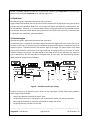
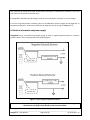
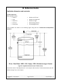
6. Electrical schematics and power supply
Gauger420 may be connected to the power supply in either a negative ground scheme or a positive
ground scheme. These are presented in the following figures.
Figure 8 - Power supply and ground schemes
Under no circumstances should the voltage on Gauger420 terminals be less than 18VDC. Voltage drop
calculation on any loop resistor should assume current of 25mA.
______________________________________________________________________________
Gauger420 – User Manual
page 18 of 69
Jan 2012 Rev 1.12
Recommendations for power supply characteristics:
• Ripple < 100 mV p-p
• Regulated switching power supply is recommended
• Rectified power supply should be avoided
• When powered by battery, avoid using a switched charger
Recommendations for the use of a PLC
• Always check that the voltage level on the terminals is at least 18VDC at a current of 25mA
• Check PLC specifications for the appropriate ground scheme options
When Gauger420 is connected to a 4-20 loop, do not connect any other device to the Gauger as this
may damage loop devices such as PLCs or loggers. When configuring Gauger with a PC through the
USB port, detach it from the 4-20 loop.
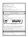
7. Electrical connections
7.1 Turn off Gauger420.
7.2 Turn the Gauger420 top cap anti-clockwise and expose the electrical connections board. Review the
connections as described in the following figure.
Figure 9 - Electrical ports
7.3 Insert cables (power and data as applicable) into the Gauger420 through one of the glands.
• Ensure that high voltage sources or cables are at least 1 meter away from Gauger420 and cables.
• Keep the electrical supply lines away from electromagnetic interference sources.
• When inserting a cable through the gland, use round cables with minimum diameter of 6 mm to
ensure that the unit remains sealed to IP67.
• Connector ports may be pulled out for easy wire connection and then re-inserted back again.
Note: Unused cable conduit must be plugged with a gland using a dummy cable stub to keep IP rating.
7.4 Connect the power cables to the appropriate ports.
______________________________________________________________________________
Gauger420 – User Manual
page 19 of 69
Jan 2012 Rev 1.12
•
•
Note that Gauger420 requires at least 24 VDC voltage on its ports.
Always make sure that sufficient voltage is present on the Gauger420 power terminals, irrespective
of any voltage drop along the supply lines
7.5 When using an external temperature sensor, connect the thermistor to the dedicated thermistor
pins. This section applies to Gauger420 models that support an external temperature sensor.
7.6 The mini-USB port is a USB device-side supporting virtual COM ports. The port may be used for
firmware upgrades and remote setup. Details about firmware upgrade are provided in the chapter:
Firmware upgrade. Contact the manufacturer or reseller for compatible PC applications. Do not use the
USB port when the Gauger is part of a 4-20 loop.
______________________________________________________________________________
Gauger420 – User Manual
page 20 of 69
Jan 2012 Rev 1.12
8. MUST BE Pamphlet
Consider copying and taking this page to the field with you.
1) Choosing location
Distance to tank walls
Flange
Acoustic noises
Electrical interference
Tank installation
Sensor
External thermistor
MUST BE
MUST BE
MUST BE
MUST BE
MUST BE
MUST BE
MUST BE
at least 30cm from walls + 10cm/1m range
fixed on a horizontal surface
far away from acoustic noises and vibrations
shielded away from power and sensor cables
far away from tank inlets, outlets, physical obstacles
exactly perpendicular to the surface of the target
in shaded location, attached to the tank body
2) Handling dead zone
Extension pipes (1)
MUST BE
Extension pipes (2)
Extension pipes (3)
MUST BE
MUST BE
of at least 3” internal diameter and 15 cm above target
(from sensor face)
with completely smooth interior surface
installed with a flange/not protruding into the tank
3) Power source
Voltage
Power source
Ripple and noise
Type
MUST BE
MUST BE
MUST BE
MUST BE
at least 18VDC on unit terminals
rated higher than 18VDC due to voltage drop
not exceeding 100mV
preferably regulated switching power supply
5) Measurement Configuration
Full/Empty, Level/Distance
Filling rate
Near blocking distance (NBD)
MUST BE
MUST BE
MUST BE
configured correctly
defined (consider the application)
set up in flange and extension pipe installations
______________________________________________________________________________
Gauger420 – User Manual
page 21 of 69
Jan 2012 Rev 1.12
III. Keypad and display
This chapter describes the keypad and display of Gauger420. The keypad and display add functionality
to Gauger420:
• Viewing measurement results and viewing information related to the system
• Configuring Gauger420
Some models of Gauger420 are provided without a display/keypad. In these models configuration of the
system is preformed with a PC. This chapter focuses on the structure and operation of the keypad and
display. Configuration of the system is described in following chapters.
1. Keypad
1.1 Navigation keys
Use the navigation keys to scroll through the display.
Left-Up
navigation
key
Right-Down
navigation key
Figure 10 - Navigation keys
1.2 Execution keys
Use the execution keys to change a digit or to execute a command (Back, Next or Sub-menu):
• To change a digit: navigate to the digit and press the Plus (+) key or the Minus (-) key.
• To execute a command: navigate to the command and press the Enter (+) key.
Remember – some changes are saved only after returning to the measurement screen. If you shut down
Gauger420 before you return to the measurement screen, your changes may be lost.
Figure 11 - Execution keys
Increase digit
or Enter
Decrease digit
______________________________________________________________________________
Gauger420 – User Manual
page 22 of 69
Jan 2012 Rev 1.12
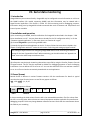
2. Navigation through menus
Gauger420 supports two menu styles which are used throughout the setup operations and are
described below. False echo scan employs another menu style and is described at the relevant section.
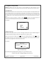
2.1 Sub-Menu style
The Sub-Menu style presents a list of vertical choices. An arrow may appear on the right hand side of the
screen if additional items can be reached when scrolling down. The scrolling is cyclic, meaning that when
you reach the last (first) item, the next step will lead you to the first (last) item. Scroll up or down, using
the navigation keys, to your selected choice and press Enter (+). This action will lead you to the next SubMenu.
The last item in the list of choices is **back**. Select **back** to return to the previous menu. The
previous menu will be displayed such that your last selection will appear first on the menu.
For example:
VALUE TO DISPLAY
Select
Distance
Level
% Distance
Figure 12 - Sub menu screens
2.2 Numeric menu style
The Numeric menu style presents you with a multi-digit number which may be modified. Navigate to
each digit and modify the digit as required by using the Plus (+) or Minus (-) keys.
When you are done with all digits, select Next to store the modified parameter. Select Back to ignore
the changes and return to the previous sub-menu. Modifications will become permanent (survive a
reset) when you navigate back to the measurement screen.
For example:
Back
EMPTY LEVEL
Enter distance from sensor face to
empty level
X1.X2X3X4 meter
Next
Figure 13 - Numeric menu
By repeatedly pressing the Right-Down navigation key, you will follow this route:
X1 X2 X3 X4 Next Back X1 X2 …
______________________________________________________________________________
Gauger420 – User Manual
page 23 of 69
Jan 2012 Rev 1.12
Conversely, by repeatedly pressing the Left-Up navigation key, you will follow the opposite route.
After pressing Next, Gauger will check the validity of your numerical entry. If your entry is outside the
acceptable boundaries, an ILLEGAL VALUE screen will be presented. You need to press any key to return
to the previous screen. A default value will replace your wrong entry. If so needed, modify the numerical
entry and press Next again.
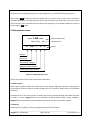
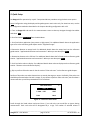
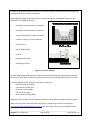
3. Measurement screen
Level 1.234 meter
EMPTY LEVEL
±¤
setup
T°
dB
Measurement report
Status reports
ID
Toolbar
Contrast
Main menu
Temperature readings
Ultrasonic echo conditions
Product identification details
Figure 14 - Measurement screen
The top line presents the current measurement information.
3.1 Status reports
Status reports appear beneath the measurement result. Reports related to ultrasonic metering issues
are presented. Ultrasonic reports include messages such as: FULL LEVEL, EMPTY LEVEL, ECHO SEARCH
and others.
The bottom line on the screen presents a toolbar with choices. Navigate through the toolbar and select
an action or report. Gauger420 halts any operations (including measurements) during navigation.
Gauger420 will automatically resume operations 30 seconds after last key has been pressed.
3.2 Contrast
Press the Plus (+) or Minus (-) keys to change visual contrast of the display.
______________________________________________________________________________
Gauger420 – User Manual
page 24 of 69
Jan 2012 Rev 1.12
3.3 Main menu / setup
Navigate to Setup and press Enter (+) to configure Gauger420. The actual configuration process is
explained in a following chapter.
3.4 Temperature readings
Navigate to the T° symbol on the toolbar and press Enter (+). The following table will be displayed:
Sens:
Cur High Low
Int
29.5 31.0
26
Ext
29.4 32
23.3
Reset
Done
Figure 15 - Temperature readings
The table is explained in the reference guide section: “Temperature sensors, units and display”. Press
Reset to reset recorded high / low temperatures or press Done to return to the measurement screen.
3.5 Ultrasonic echo conditions
Navigate to the dB symbol and press Enter (+). You will be presented with the measured echo amplitude
and the maximum amplitude available. The amplitudes are presented in dB relative to a system
threshold amplitude. Echo amplitude should be above threshold amplitude for reliable measurement.
Echo strength between 3dB and 8db (maximum) is reliable. Echo amplitude refers to the echo measured
just prior to navigating through the toolbar. Press Done to return to the measurement screen.
3.6 Product identification details
From the measurement screen, navigate to the ID symbol on the toolbar and press Enter (+). Product
information will be displayed: Serial Number and Part Number. Press Back to return to the
measurement screen or navigate to one of the options: Software information (SW), Hardware
information (HW) or Manufacturing Date information (Date). SW screen will display firmware versions
of the embedded application and of the embedded Boot-Loader. Press Back to return to the previous
menu. HW screen will display product information regarding sensor type and model type. Press Back to
return to the previous menu. Date screen will present the date of manufacturing. Press Back to return to
the previous menu.
______________________________________________________________________________
Gauger420 – User Manual
page 25 of 69
Jan 2012 Rev 1.12
IV. Configuration with the keypad and display
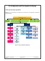
1. Menu and sub-menu organization
Gauger420 menus and submenus are organized in a tree-like format. The organization is described in
the following figure.
Figure 16 - Menu and submenu organization
______________________________________________________________________________
Gauger420 – User Manual
page 26 of 69
Jan 2012 Rev 1.12
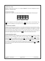
2. Quick Setup
Set Gauger420 for operation by a quick 7-step wizard-driven procedure using the basic menu option.
Note: Configuration using the display and keypad supports metric units only. For American units, use the
PC configuration method as described in the chapter describing configuration with a PC.
a. Turn on Gauger420 and wait for the measurement screen to show up. Navigate through the toolbar
and select setup.
b. Scroll and select Basic Setup from the Main Menu.
c. Scroll and select application (Low power or High power). For additional details about the application
type refer to the reference guide chapter under: “Application type”.
d. Determine distance to empty level. For additional details about the empty level see the reference
guide section: “application dimensions and constraints”. When you are done press Done.
e. Determine distance to the full level. For additional details about the full level see the reference guide
section: “application dimensions and constraints”. When you are done press Done.
f. Scroll and select value to display. For additional details about value-to-display see the reference guide
section: “Distance units and value to display”.
g. Skip or perform false echo search. See the section “False echo scan” in the reference guide chapter.
Perform a false echo scan when obstructions are nearby the target or sensor. Preferably, false echo scan
should be performed when the tank is empty. If you choose to perform false echo scan, wait for about a
minute and then you will be presented with a list of echoes.
False Echo Select
1
0.17
2 New 0.25
Save
√
1
1408
1207
Next
Figure 17 - False echo scan screen
Scroll through the listed echoes and press Enter (+) on each echo you would like to ignore during
measurement. Each such echo will be designated by a √ sign. The number of selected echoes is
______________________________________________________________________________
Gauger420 – User Manual
page 27 of 69
Jan 2012 Rev 1.12
presented on the top-right edge of the screen. Press Save to store your selection and Next to proceed to
the next sub-menu. To un-select an echo, scroll to that echo and press Enter (+) again. If you choose to
perform false echo scan a second time, new echoes which were not identified during the first scan will
be reported as “new”.
The Gauger is now ready for measurements.
Parameters not determined during quick setup procedure will take their default value and may be
modified later using the Advanced Setup menu.
Note: Always verify then re-verify that your basic settings are correct including
distance to empty level, distance to full level, level or distance choice. Most wrong
readings originate from incorrect setup.
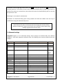
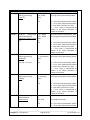
3. Advanced settings
Gauger420 supports a set of advanced settings. These settings are classified under four different
categories: 4-20, HART, Algorithm and Device state. The following items may be modified under each
category:
Category
4-20
HART
Sub menu items
See section in reference guide…
Variable represented
Value represented
“4-20 communications”
“4-20 communications”
Error signal
“4-20 communications”
On / Off
HART address
PV, SV, TV, QV presentation
“HART communications”
“HART communications”
“HART communications”
Far blocking distance
Near blocking distance
Filling rate
Temperature units
“Application dimensions & constraints”
“Application dimensions & constraints”
“Filling rate”
“Temperature sensors, units and display”
Reset to defaults
Operating hours
“Reset and operating hours”
“Reset and operating hours”
Notes
4mA
20mA
3.6mA
22mA
Hold
Algorithm
Device state
______________________________________________________________________________
Gauger420 – User Manual
page 28 of 69
Jan 2012 Rev 1.12
To execute any of the advanced settings, follow these steps: Turn ON Gauger420 and wait for the
Measurement screen to show up. Navigate and select Setup. Then scroll and select Advanced Setup
from the Main Menu. Now select the required category (GSM, Algorithm or Device state) and follow the
screen instructions. When done, scroll and press **back** to return to the Main Menu an then scroll
and select the measurement display.
Each item may either present a selection of sub-items to choose from or may require entry of a numeric
field.
If you are not sure what sub-item to select or how the numeric field should be modified, than
leave the default values as is.
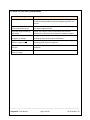
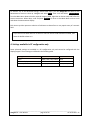
4. Settings available in PC configuration only
Some advanced settings are available in a PC configuration only and cannot be configured with the
display/keypad. These settings are defined in the following table.
Setting
Units
Value to display
Tank shape and dimensions
Options
Meter, feet, Liter, Gallon
Volume
Cubic, Cylindrical
PC Command
UNT
VAL
CUB, CYLV, CYLH
______________________________________________________________________________
Gauger420 – User Manual
page 29 of 69
Jan 2012 Rev 1.12
V. Configuration with a PC
1. Introduction
Gauger420 is pre-configured at the factory to default settings. See reference guide section: “Default
Values”. The system is delivered to the user ready for operation. Some configuration parameters should
be re-configured by the user for proper field application. Gauger420 can be configured by a simple PC
tool.
Configuration by PC may be used in lieu of configuring with the integral keypad and display. PC
configuration provides the user with the full set of configuration items. Furthermore, configuration by
PC allows the user to clone fielded Gauger420 systems. For this cloning process, the user is required to
prepare one text file and download that file into all relevant Gauger420 systems. Once this configuration
file is prepared, the downloading process takes a few seconds and makes redundant any manual keypad
based operation.
Section 2 below begins by demonstrating a sample configuration text file.
Section 3 handles the downloading operation. The download process involves use of a standard
Windows application – HyperTerminal. The setup of HyperTerminal is explained in the second section
and parts of it may be skipped by those who are already familiar with this tool. Section 4 presents
possible responses from Gauger420 –whether good or erroneous responses. Section 5 is a list of all
configuration items. Section 6 provides some configuration file example.
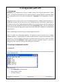
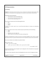
2. Preparing a configuration text file
2.1 Sample files
The following text file was created using Windows Notepad application and demonstrates the essence
of the configuration file:
Digest line by line:
• Reset Gauger420 to its default values.
• Value to Display is LEVEL
• Unit system is Metric
______________________________________________________________________________
Gauger420 – User Manual
page 30 of 69
Jan 2012 Rev 1.12
•
•
EMPTY LEVEL is set to a distance of 6.0 meters
FULL LEVEL is set to a distance of 0.70 meters
If you are unfamiliar with terms such as empty level or full level read reference guide section:
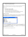
“Application dimensions and constraints”. Next is a slightly more complex configuration file:
Summary notes:
• Each line begins, and ends, with a $ sign.
• All commands are made of Capital letters.
• Each command is immediately adjacent to the first $ sign.
• There is a blank between the command and the related parameter.
• It is highly recommended to begin each configuration file with RSD then VAL then UNT.
Other combinations, while not illegal, may result in setup misinterpretation.
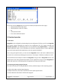
2.2 Multi Value commands
Some configuration items are assembled from two values or more. For example, the dimensions of a
vertical cylindrical tank (prefix CYLV) are height and diameter. These two values are both included with a
comma in between the two values. The next figure illustrates the use of the comma.
The second line instructs Gauger420 to display VOLUME results (rather then LEVEL or DISTANCE). The
third line instructs Gauger420 to display volume in liters. The last line instructs Gauger420 to set the
tank as a vertical cylindrical tank with height of 4.5 meter and diameter of 3.00 meters. Comma should
always separate between values on the same line.
The final example demonstrates the configuration of 4-20.
______________________________________________________________________________
Gauger420 – User Manual
page 31 of 69
Jan 2012 Rev 1.12
The last line instructs Gauger420 to set the 4-20 as follows (interpreted from left to right):
• 4mA represents Level of 0.0 meters
• 20mA represents Level of 5.3 meters
• NA
• 4-20 represents LEVEL
• Error state is HOLD LAST VALUE
3. Download operation
3.1 Procedure
Gauger420 can be configured by downloading the text configuration file from your PC into Gauger420.
The previous chapter described the making of the configuration file. This chapter describes the
download procedure. The download process can be preformed using HyperTerminal – a Microsoft
standard application which is part of Windows XP and earlier operating systems. Similar applications
may also be used. HyperTerminal application can also be copied to Windows 7.
Prior to using the HyperTerminal, you must connect Gauger420 to the PC and install a USB-Serial driver
on the PC. You can do that by following the instructions in the chapter: “USB driver installation on a PC”.
You should find out the COM port number that Gauger420 is using on the PC. Gauger420 must be in the
measurement screen during download procedure. Two PC applications trying to access Gauger420 will
conflict with each other. Avoid having two such applications running at the same time.
3.2 Launching and setting up HyperTerminal
This section assumes you are using Windows XP. Similar procedures apply to other operating systems.
3.2.1 Go to Start Menu and then Open Programs.
3.2.2 Open Accessories, then Open Communications then Open HyperTerminal.
3.2.3 Press NO when asked about “default telnet program”
______________________________________________________________________________
Gauger420 – User Manual
page 32 of 69
Jan 2012 Rev 1.12
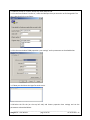
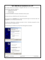
3.2.4 When prompt for a name, choose any name and press OK.
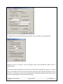
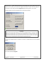
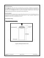
3.2.5 In the next window “Connect to”, select the COM port that you intend to use for Gauger420. This
part is described in the next figure:
3.2.6 In the next window “COM properties - port settings” set the parameters as described below:
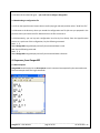
3.2.7 Now you should see the HyperTerminal screen:
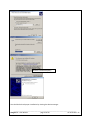
3.2.8 Select the File tab (on the top left side) and choose properties then settings and set the
parameters as described below:
______________________________________________________________________________
Gauger420 – User Manual
page 33 of 69
Jan 2012 Rev 1.12
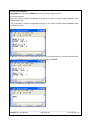
3.2.9 Now press on ASCII setup (bottom right side) and set the parameters as described below:
Especially note the “Line Delay” and the “Character delay” which are not the default values of
HyperTerminal.
Note: When using the USB port for local serial data monitoring (see appropriate chapter), you should
return to the default values of the screen above and specifically uncheck “Append line feeds to incoming
line ends”. And vice verse, if you revert to configuration of Gauger420 through the USB interface, make
sure to set the parameters of the screen above correctly.
______________________________________________________________________________
Gauger420 – User Manual
page 34 of 69
Jan 2012 Rev 1.12
3.2.10 Press OK and then OK again – you are all set to configure Gauger420.
3.3 Downloading a configuration file
3.3.1 From the HyperTerminal screen select transfer (top right side tab) and then select “Send Test File”.
3.3.2 Browse to the directory where you stored the configuration text file (the one you prepared in the
previous section) and select that file. Double click on the file to transmit it.
3.3.3 Alternatively, you can key each configuration item line by line directly from the HyperTerminal
screen. As a quick test of this configuration, key the following command:
$VAL 1 $
Watch Gauger420 integral display and verify that measured data is Level.
Now key the following command:
$VAL 2 $
Watch Gauger420 integral display and verify that measured data is Distance.
4. Responses from Gauger420
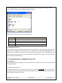
4.1 Good response
GaugerGSM should reply with an OK response to each command accompanied by the command name.
The next example shows five legal commands.
______________________________________________________________________________
Gauger420 – User Manual
page 35 of 69
Jan 2012 Rev 1.12
4.2 Erroneous responses
GaugerGSM will reply with an ERROR response to a wrong configuration item.
In the next example:
EMP = 8.9 meters is illegal for GaugerGSM-75 (maximum is 8 meters) and will produce ERROR #5: Value
exceeds upper limit.
FUL = 0.13 meters is illegal for GaugerGSM (minimum is 0.15 meters) and will produce ERROR #6: Value
is below lower limit.
Additional errors may occur if command is wrong. In the next example, the non-existent command EGP
results in ERROR#4 and a non existent value (VAL=9) results in ERROR#7.
Finally, misalignment of $ signs may occur as follows:
______________________________________________________________________________
Gauger420 – User Manual
page 36 of 69
Jan 2012 Rev 1.12
In the example above, the closing $ was not typed and the system is waiting for this $ sign. In these
cases, type $ and re-enter the complete command as follows:
Some of the common error numbers are listed below:
Error code
4
5
6
7
Most probable cause
Wrong command name or command not adjacent to $ sign
Value is exceeds upper legal limit
Value is below lower legal limit
Value is illegal
4.3 Communication Errors
The erroneous responses described indicate that the link between PC and Gauger420 is operating fine
and that the commands are of wrong nature. If no responses are received from Gauger420 or if the
responses carry unfamiliar characters, the communication link between the PC and Gauger420 is not
performing. In this case, you need to check the physical cabling, verify the HyperTerminal settings and
then restart this application again.
5. List of commands for configuration from a PC
5.1 Conventions
The following conventions apply for the list of commands. These conventions refer to the values allowed
for each parameter.
5.1.1 Range of number values
A range of number values is presented with a hyphen. For example: 0.150-8.000. This entry means that
the value may be any number between 0.150 and 8.000. Always use the decimal point. The number of
decimal digits may be less than three.
______________________________________________________________________________
Gauger420 – User Manual
page 37 of 69
Jan 2012 Rev 1.12
5.1.2 Range of whole number values
A range of whole number values is presented with a hyphen. For example: 1-99. This entry means that
the value may be any whole number between 1 and 99.
5.1.3 Several distinct values
When a parameter can be one of a few distinct values,
explanation. For example:
Command Command Description Possible values
VAL (3)
Value to display
1
2
3
each value is listed on separate lines with an
Value description
Level
Distance
Volume (set also tank shape)
5.1.4 Two parameters for the same command
An entry such as 1-9999 , 0.150-8.000 means that the command is made of two parameters and
requires two values. A comma separates the two values. In this example the first value may be any
whole number between 1 and 9999. The second value may be any number between 0.150 and 8.000.
5.1.5 Two parameters with one parameter fixed
An entry such as 1-99 , 0 means that the configuration item requires two values but the second value
must be 0. The first value in this example may be any whole number between 1 and 99.
The user may select one of two units systems: Metric or American. A separate command list is provided
below for each unit system. The user can select his/her preferred unit system with the UNT command.
______________________________________________________________________________
Gauger420 – User Manual
page 38 of 69
Jan 2012 Rev 1.12
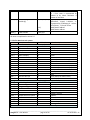
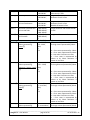
5.2 List for Metric unit system
Item
Description
APP (1)
EMP (2)
FUL (2)
VAL (3)
UNT (3)
UNT (3)
FBD (2)
NBD (2)
RAT (4)
TMP (5)
SNS (5)
CUB (7)
CYLV (7)
CYLV (7)
CYLH (7)
CYLH (7)
Possible values
Value description
Basic setup (Metric)
Application type
0
High power
1
Low power
Empty level
0.150 – 8.000
Distance in meters
Full level
0.150 – 8.000
Distance in meters
Value to display
1
Level
2
Distance
3
Volume (set also tank shape)
4
% Level
5
% Distance
6
% Volume (set also tank shape)
7
Flow (see also OCF command)
8
%Flow
Units for VAL=1,2,4,5
1
Meter
2
Feet (see list for American units)
Units for VAL=3,6
3
Liter
4
US Gallons (see list for American units)
Advanced setup (Metric)
Far blocking distance
0.150 – 8.000
Distance in meters
Near blocking distance
0.150 – 8.000
Distance in meters
Filling (tracking) rate
0
1 meter / minute
1
2 meter / minute
2
5 meter / minute
3
10meter / minute
Temperature unit system
3
Celsius
4
Fahrenheit
Temperature sensor
0
Internal sensor
1
External sensor
2
Average of both
Tank shapes and dimensions (Metric)
Cubic tank
0.00-99.99 , 0.00- Width and depth (horizontal
99.99
dimensions) in meter.
Vertical cylindrical tank
0.00-99.99 ,
Height of tank = EMP value in meter
0.00-99.99 , 0
Diameter of tank in meter
Vertical cylindrical tank
0.00-99.99 ,
Height of tank = EMP value in meter
with concave bottom
0.00-99.99 ,
Diameter of tank in meter
0.00-99.99
Breadth of bottom in meter
Horizontal cylindrical tank 0.000-99.99 ,
Length, diameter and curved breadth
with curved sides
0.000-99.99 ,
in meter.
0.001-99.99
Horizontal cylindrical tank 0.000-99.99 ,
Length and diameter in meter.
with flat sides
0.000-99.99 ,
0
______________________________________________________________________________
Gauger420 – User Manual
page 39 of 69
Jan 2012 Rev 1.12
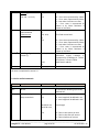
9
TWOW ( )
TWOW (9)
TWOW (9)
TWOW (9)
TWOW (9)
4-20 and HART (Metric)
4-20mA
configuration 0.0 – 8.000,
The low Level represented by 4mA.
when representing:
0.0 – 8.000,
The high Level represented by 20mA.
Level (2)
20.0,
0,
0-3
0 – Error state represented by 3.6mA.
1 – Error state represented by 22mA.
2 – Last value is held at error state.
3 – Error state is represented by
3.6mA or by 22mA whichever is
nearer to last value.
4-20mA
configuration 0.15 – 8.000,
The short Distance presented by 4mA.
when representing:
0.15 – 8.000,
The long Distance presented by 20mA.
Distance (reverse Level) 20.0,
(2)
3,
0-3
0 – Error state represented by 3.6mA.
1 – Error state represented by 22mA.
2 – Last value is held at error state.
3 – Error state is represented by
3.6mA or by 22mA whichever is
nearer to last value.
4-20mA
configuration 0 – min Volume, The small Volume presented by 4mA.
when representing:
0 – max Volume, The large Volume presented by 20mA.
2
Volume( )
20.0,
2,
For VAL = 3, 6 only.
0-3
0 – Error state represented by 3.6mA.
1 – Error state represented by 22mA.
2 – Last value is held at error state.
3 – Error state is represented by
3.6mA or by 22mA whichever is
nearer to last value.
4-20mA
configuration 0 – min Flow,
The small Volume presented by 4mA.
when representing:
0 – max Flow,
The large Volume presented by 20mA.
Flow(2)
20.0,
1,
0-3
0 – Error state represented by 3.6mA.
1 – Error state represented by 22mA.
2 – Last value is held at error state.
3 – Error state is represented by
3.6mA or by 22mA whichever is
nearer to last value.
4-20mA
configuration 0,
when disabled:
0,
Fixed current
4.0 - 20.0,
The fixed current level.
4,
0-3
0 – Error state represented by 3.6mA.
1 – Error state represented by 22mA.
______________________________________________________________________________
Gauger420 – User Manual
page 40 of 69
Jan 2012 Rev 1.12
HART (10)
HART (9)
HART configuration and 0-6, 0-6,0-6, 0-6,
enable (5)
HART Disable
0-15,
1
0,0,0,0,0,0
2 – Last value is held at error state.
3 – Error state is represented by
3.6mA or by 22mA whichever is
nearer to last value.
PV, SV, TV, QV where:
0-Distance, 1-Level, 2-Volume, 3–
Temperature, 4-%Distance, 6 - %Level,
6-%Volume, , 7-Flow, 8-%Flow
HART device address
HART device address
All notes are explained in section 5.5
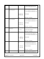
5.3 List for American unit system
Item
Description
APP (1)
EMP (2)
FUL (2)
VAL (3)
UNT (3)
UNT (3)
FBD (2)
NBD (2)
RAT (4)
TMP (5)
SNS (5)
Possible values
Value description
Basic setup (American)
Application type
0
High power
1
Low power
Empty level
0.50 – 26.00
Distance in feet
Full level
0.50 – 26.00
Distance in feet
Value to display
1
Level
2
Distance
3
Volume (set also tank shape)
4
% Level
5
% Distance
6
% Volume (set also tank shape)
6
% Volume (set also tank shape)
7
Flow (see also OCF command)
Units for VAL=1,2,4,5
1
Meter (see list for metric units)
2
Feet
Units for VAL=3,6
3
Liter (see list for metric units)
4
Gallons (US)
Advanced setup (American)
Far blocking distance
0.50 – 26.00
Distance in feet
Near blocking distance
0.50 – 26.00
Distance in feet
Filling (tracking) rate
0
3 feet / minute
1
6 feet / minute
2
15 feet / minute
3
30 feet / minute
Temperature unit system
3
Celsius
4
Fahrenheit
Temperature sensor
0
Internal sensor
1
External sensor
2
Average of both
Tank shapes and dimensions (American)
______________________________________________________________________________
Gauger420 – User Manual
page 41 of 69
Jan 2012 Rev 1.12
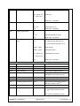
CUB (7)
CYLV (7)
CYLV (7)
CYLH (7)
CYLH (7)
TWOW (9)
TWOW (9)
TWOW (9)
TWOW (9)
Cubic tank
0.00-300.00 ,
Width and depth (horizontal
0.00-300.00
dimensions) in feet.
Vertical cylindrical tank
0.00-300.00 ,
Height of tank = EMP value in feet
0.00-300.00 ,
Diameter of tank in feet
0
Vertical cylindrical tank
0.00-300.00 ,
Height of tank = EMP value in feet
with concave bottom
0.00-300.00 ,
Diameter of tank in feet
0.01-300.00
Breadth of bottom in feet
Horizontal cylindrical tank 0.000-300.00 ,
Length, diameter and curved breadth
with curved sides
0.000-300.00 ,
in feet.
0.001-300.00
Horizontal cylindrical tank 0.000-300.00 ,
Length and diameter in feet.
with flat sides
0.000-300.00 ,
0
4-20 and HART (American)
4-20mA
configuration 0.0 – 26.00,
The low Level represented by 4mA.
when representing:
0.0 – 26.00,
The high Level represented by 20mA.
Level (2)
20.0,
0,
0-3
0 – Error state represented by 3.6mA.
1 – Error state represented by 22mA.
2 – Last value is held at error state.
3 – Error state is represented by
3.6mA or by 22mA whichever is
nearer to last value.
4-20mA
configuration 0.50 – 26.00,
The short Distance presented by 4mA.
when representing:
0.50 – 26.00,
The long Distance presented by 20mA.
Distance (reverse Level) 20.0,
(2)
3,
0-3
0 – Error state represented by 3.6mA.
1 – Error state represented by 22mA.
2 – Last value is held at error state.
3 – Error state is represented by
3.6mA or by 22mA whichever is
nearer to last value.
4-20mA
configuration 0 – min Flow,
The small Volume presented by 4mA.
when representing:
0 – max Flow,
The large Volume presented by 20mA.
Flow(2)
20.0,
1,
0 – Error state represented by 3.6mA.
0-3
1 – Error state represented by 22mA.
2 – Last value is held at error state.
3 – Error state is represented by
3.6mA or by 22mA whichever is
nearer to last value.
4-20mA
configuration 0 – max Volume, The small Volume presented by 4mA.
when representing:
0 – max Volume, The large Volume presented by 20mA.
______________________________________________________________________________
Gauger420 – User Manual
page 42 of 69
Jan 2012 Rev 1.12
Volume(2)
For VAL = 3, 6 only.
TWOW (9)
HART (10)
HART (10)
20.0,
2,
0-3
4-20mA
configuration 0,
when disabled:
0,
Fixed current
4.0 - 20.0,
4,
0-3
HART configuration and 0-6, 0-6,0-6, 0-6,
enable (5)
HART Disable
0-15,
1
0,0,0,0,0,0
0 – Error state represented by 3.6mA.
1 – Error state represented by 22mA.
2 – Last value is held at error state.
3 – Error state is represented by
3.6mA or by 22mA whichever is
nearer to last value.
The fixed current level.
0 – Error state represented by 3.6mA.
1 – Error state represented by 22mA.
2 – Last value is held at error state.
3 – Error state is represented by
3.6mA or by 22mA whichever is
nearer to last value.
PV, SV, TV, QV where:
0-Distance, 1-Level, 2-Volume, 3–
Temperature, 4-%Distance, 6 - %Level,
6-%Volume, 7-Flow, 8-%Flow
HART device address
All notes are explained in section 5.5
5.4 List for unified commands
Item
OCF
OCF (17)
Description
Possible values
Value description
Open Channel Flow (OCF)
No OCF
0
To be used for disabling a previously
defined OCF
Rectangular suppressed
1,
sharp crested weir
0-1,
0 - crest length will be defined in cm
1- crest length will be defined in inch
20-300 for cm
12-96 for inch,
Crest length
0-4
0 – flow in cubic meter per hour
1 – flow in cubic feet per second
2 – flow in Gallons per minute
______________________________________________________________________________
Gauger420 – User Manual
page 43 of 69
Jan 2012 Rev 1.12
3 – flow in liter per second
4 – flow in Million gallons per day
OCF (17)
17
OCF ( )
17
OCF ( )
OCF (17)
17
OCF ( )
17
OCF ( )
Rectangular contracted
sharp crested weir
Trapezoidal (Cipolletti)
sharp crested weir
2,
0-1,
20-300 for cm
12-96 for inch,
Crest length
0-4
3,
0-1,
Flow units – see above
30-300 for cm
12-96 for inch,
Crest length
0-4
V-Notch (Triangular) sharp 4,
crested weir
0,
22.5 - 90,
0-4
Parshall Flume
5,
0-1,
Palmer-Bowlus Flume
H-Flume
0 - crest length will be defined in cm
1- crest length will be defined in inch
0 - crest length will be defined in cm
1- crest length will be defined in inch
Flow units – see above
V-Notch angle in degrees
Flow units – see above
0 - throat width will be defined in cm
1- throat width will be defined in inch
15 - 360 for cm
6 - 144 for inch,
throat width
0-4
6,
0-1,
Flow units – see above
15 - 75 for cm
6 - 72 for inch,
Conduit diameter
0-4
7,
0-1,
Flow units – see above
0- conduit diameter defined in cm
1- conduit diameter defined in inch
0 - flume size will be defined in cm
______________________________________________________________________________
Gauger420 – User Manual
page 44 of 69
Jan 2012 Rev 1.12
1 - flume size will be defined in inch
OCF (17)
OCF (17)
OCF (17)
RSD (6)
RSC (6)
RST (6)
STAT
GMAN
ENDT (8)
DSDT (8)
FES(19)
FES(19)
FILT
Khafagi-Venturi Flume
Leopold-Lagco Flume
Manning flow for circular
pipes
15 - 135 for cm
6 – 54 for inch,
flume size
0-4
8,
0,
12 - 160
0-4
8,
1,
4 - 72
0-4
9,
0-1,
Flow units – see above
0.000 - 1.000
0.000 – 0.200
Slope of pipe
Roughness factor
15 – 900 for cm
6 – 350 for inch
Pipe diameter in inches
Flume width in cm
Flow units – see above
Conduit diameter in inches
Flow units – see above
0 - pipe diameter defined in cm
1 – pipe diameter defined in inch
0-4
Flow units – see above
Reset, Verify Settings, ID, False Echo, Intermittent Echo, Gas Velocity
Reset to factory defaults
None
Reset hour counter
None
Restart Gauger
None
Report settings
0
Send report to HyperTerminal
Get Manufacturer data
None
Response is serial number and
manufacturer date: dd-mm-yyyy
Enable serial monitoring
None
Disable serial monitoring
None
List fixed ultrasonic echoes None
HyperTerminal will display a list of
ultrasonic echoes – see (19).
Set fixed echo as false
0-5
Index of echo (19)
Ignore intermittent echo
0 - 20
0 - do not ignore intermittent echoes
1 - Ignore short duration echoes
…
20 – Ignore long duration echoes
______________________________________________________________________________
Gauger420 – User Manual
page 45 of 69
Jan 2012 Rev 1.12
GCOF
Gas Velocity Coefficient
0.3 – 5.0
Speed of sound in the measurement
area is higher by this multiplicative
coefficient.
All notes are explained in section 5.5
5.5 Notes
Note #
(1)
(2)
(3)
(4)
(5)
(6)
(7)
(9)
(10)
(17)
(18)
(19)
See detailed information in Reference guide chapter…
Section: “Application type”
Section: “Application dimensions and constraints”
Section: “Distance units and value to display“
Section: “Filling rate”
Section: “Temperature sensors, units and temperature display”
Section: “Reset and operating hours”
Section: “Volume measurement”
Section: “4-20 communication”
Section: “HART communication”
Section: “Open Channel Flow”
Section: “Gas Velocity Coefficient”
Section: “False Echo Scan by PC”
______________________________________________________________________________
Gauger420 – User Manual
page 46 of 69
Jan 2012 Rev 1.12
6. Some useful examples
6.1 Basic setup
$RSD $
$VAL 1 $
$UNT1 $
$APP 0 $
$EMP 8.0 $
$FUL 0.15 $
$VAL 1 $
Reset to default
Value to display is LEVEL
Unit system is metric
Application is high power
Distance to empty level is 8 meter
Distance to full level is 0.15 meter
Value to display is level
6.2 Advanced setup
$RSD
$VAL 1 $
$UNT 1 $
$FBD 8.0 $
$NBD 0.4 $
$RAT 3 $
$TMP 3 $
$SNS 0 $
$CYLV 5.0 , 2.0 $
Reset to default
Value to display is level
Unit system is metric
Far blocking distance is 8 meters
Near blocking distance is 0.4 meter
Tracking rate is 10 meters per minute
Temperature unit is Celsius
Temperature sensor is the internal
Tank is vertical cylindrical, height 5m and diameter 2m
$TWOW 0.0 , 15700 , 20 , 2 , 1 $
4mA represents 0 liters, 20mA represents 15700 liters, error is
represented by 22mA
Note: Always verify then re-verify that your basic settings are correct including
distance to empty level, distance to full level, level or distance choice. Most wrong
readings originate from incorrect setup.
______________________________________________________________________________
Gauger420 – User Manual
page 47 of 69
Jan 2012 Rev 1.12
VI. Firmware upgrade tool
1. Introduction
Gauger420 firmware can be upgraded in the field. The upgrade procedure takes less than 5 minutes but
should be done carefully to avoid damage to the system. This feature is useful for adding new features
to your Gauger420 system and for fixing bugs.
•
•
•
•
Perform firmware upgrade only when authorized to do so by the manufacturer or re-seller.
While upgrading Gauger420, record your steps and also record any messages that appear on-screen.
This will aid in troubleshooting a defective upgrade process.
Most stored settings will usually not be lost when upgrading the firmware.
Use only the updated firmware provided by the manufacturer or re-seller.
2. You will need
(a) PC with minimum requirements: Windows XP Service Pack 2 or Windows7/16 bit, CD drive USB port
and administrator rights. The firmware upgrade tool was also tested on Windows7/32 bit.
(b) Gauger420 Installation CD.
(c) New Gauger420 firmware which is authorized for upgrading your Gauger420.
3. Installation of Firmware Upgrade Tool and USB driver
(a) Insert the installation CD, select and run Setup.exe in the main directory of the CD.
(b) Follow the on-screen instructions. When prompted for an installation directory, keep the default
installation directory: “c:\program files\solidat\GaugerFirmwareUpgradeTool” or choose another
directory.
(c) When complete, check for new icon on your desktop and new program entry in the programs list.
(d) Install Gauger420 USB driver by following instructions in chapter: “USB driver installation on a PC”.
4. Upgrade procedure
(a) Copy the new Gauger420 firmware (e.g. xyz.bin) to a directory of your choice.
(b) Run Gauger Firmware Upgrade Tool by clicking on the proper desktop icon.
(c) Wait until the proper COM port is identified (the port connected with Gauger420) then press OK on
the pop-up window.
Verify that current firmware version is displayed on the top line.
______________________________________________________________________________
Gauger420 – User Manual
page 48 of 69
Jan 2012 Rev 1.12
(d) Click on the “…” button, browse and select the new firmware (e.g. xyz.bin). When the new name
appears on the windows, you can press the “upgrade new firmware” button. Follow the progress and
instructions on-screen. After some while, Gauger420 display will be turned off – this is normal.
During the upgrade, you will see a progressive bar on the window as follows:
Be patient!
If you do not see the bar starting, or if the bar has stopped moving – just wait! If you
disconnect the Gauger while in the middle of the upgrade process, the internal software may
be impaired and may require returning to the factory. If the bar has not started or has stopped,
wait for at least 10 minutes before reconnecting and restarting the process.
(e) Wait for the upgrade process to complete. The process is complete when you see the following
window:
Now click OK and Restart Gauger420.
______________________________________________________________________________
Gauger420 – User Manual
page 49 of 69
Jan 2012 Rev 1.12
5. Troubleshooting the firmware upgrade process
Symptom
Installing Upgrade Tool
Installation of the upgrade tool
halts due to .NET Framework
missing.
Installation of the upgrade tool
halts due to user permissions
Upgrading the firmware
COM port is not found
Or current firmware version is
not displayed
Upgrade process has halted
Gauger420 display stays blank
after installation and restart
Recommendation
Install .NET Framework on you PC (2.0 or above). See
http://www.microsoft.com/downloads/details.aspx?familyid=0856eacb4362-4b0d-8edd-aab15c5e04f5&displaylang=en
Verify that you are a local administrator on the PC.
(1) Make sure Gauger420 is turned on. Disconnect and then connect
again the USB cable.
(2) Select the Communication tab. Try automatic port selection then
try manual port selection.
(3) Shut off the Upgrade Tool then verify with the Windows Task
Manager that a Gauger process is not running. Run the Upgrade Tool
again.
Wait for 10 minutes. Restart the application. Restart you PC and try
again.
Restart your PC and try again.
______________________________________________________________________________
Gauger420 – User Manual
page 50 of 69
Jan 2012 Rev 1.12
VII. Serial data monitoring
1. Introduction
GaugerGSM may be monitored locally. Gauger420 may be configured to send information to a PC over
the RS485 interface (for models supporting RS485) and that information may be viewed with a
HyperTerminal application. This feature is useful for field monitoring and for debugging purposes.
Information being sent by Gauger420 includes measured data such as Distance and Temperature and
internal system variables.
2. Installation and operation
(a) For monitoring over RS485, install the USB driver for Gauger420 as described in the chapter: “USB
Driver installation on a PC”. You may have done so already for the “PC configuration utility” or for the
“Firmware upgrade application”. In that case, there is no need to do it again.
(b) Connect Gauger420 to your PC using a RS485 cable.
(c) Launch the HyperTerminal application on the PC. To do so, follow the instructions included in the
chapter “Configuration with a PC” under the sub-section “Launching and setting up HyperTerminal”.
The settings of HyperTerminal for configuring GaugerGSM and for serial monitoring are identical
except for the item “Append Line Feed”. When monitoring, you should uncheck the “Append Line
Feed” item in the ASCII setup to avoid extra lines.
(d) Information may be simply viewed or gathered into a text file by using the Transfer /Capture Text tab
of HyperTerminal. This file may be requested by SolidAT for debugging purposes of some challenging
installations. You can define this file as txt or csv. You can also define the file as txt and later rename it
to csv. A csv file can then be conveniently viewed with an excel application.
3. Record format
Record format is different in various firmware versions. Call the manufacturer for details. A typical
record on the HyperTerminal screen or text file may appear as follows:
220, 1.532, 1.531, 2, 1, 32, 67
A csv file will appear as follows:
220
Index
1.532
1.531
2
1
32
67
Distance
In these recordings the third column from the left is the measured distance data. The first column from
the left is a running index. Other columns are internal equipment variables applicable for manufacturer
debugging purposes. Fields may change between software versions. Check with the manufacturer about
the fields in your recording.
______________________________________________________________________________
Gauger420 – User Manual
page 51 of 69
Jan 2012 Rev 1.12
VIII. USB Driver Installation on a PC
This chapter describes the installation of Gauger420 USB drivers on a PC. The driver installation is
required when using the PC / Laptop for:
• Configuration of Gauger420
• Serial monitoring
• Firmware upgrade
The drivers were tested on XP Windows and Windows 7/32 bit systems.
(a) Copy the directory “SolidAT Drivers XP” from the CD to your PC.
(b) Connect the PC to Gauger420 using a USB cable. Keep cable length to less than two meters. Turn
Gauger420 on (if not already powered by the USB).
(c) Follow the standard driver installation instructions on the PC. Whenever prompted for a driver,
select the location of “SolidAT Drivers XP”.
(d) The following set of windows may aid you when following with the installation.
______________________________________________________________________________
Gauger420 – User Manual
page 52 of 69
Jan 2012 Rev 1.12
Choose “Continue Anyway”…
You should also check proper installation by viewing the device manager:
______________________________________________________________________________
Gauger420 – User Manual
page 53 of 69
Jan 2012 Rev 1.12
Gauger operates with USB to Serial (COM 5 in this case)
If the USB driver installation failed, a “?” sign may be listed at the “Ports” item. In other cases, the driver
may be listed under “Other Devices” item. In both cases, uninstall the device and than re-install it again.
______________________________________________________________________________
Gauger420 – User Manual
page 54 of 69
Jan 2012 Rev 1.12
IX. Reference Guide
Application dimensions and constraints
(a) Basic dimensions
Basic variables include:
• Distance
• Level
• Dead zone
• Full level
• Empty level
•
•
•
•
•
Distance to full level
Distance to empty level
Maximum range
Near blocking distance
Far blocking distance
These variables are shown on the following figure along with the “fundamental interdependency
equation”.
15 cm = Dead Zone < NBD < Full < Empty < FBD < Maximum range = 8 meter
Figure 18 - Application dimensions (for 75 KHz sensor)
See also the section “Interdependencies” in this chapter and the section “4-20 communications (d) 4-20
default settings” later in this chapter.
______________________________________________________________________________
Gauger420 – User Manual
page 55 of 69
Jan 2012 Rev 1.12
(b) Distance to empty level
Distance to empty level is defined as the distance from the face of the sensor to the bottom-most
surface of the target to be measured. For typical installation in tanks, the bottom-most surface is usually
the bottom of the tank.
Gauger 75 KHz supports a maximum range of 8 meters and the default value for distance to empty level
is 8 meters. The user is cautioned however that the maximum practical range depends on target
characteristics. Range of 8 meters may be achieved with quiet liquid surface targets. As a rule of thumb,
user no more than 5 meters for solids, turbulent liquids, when the air medium is not clear or when
interferences exists. You may verify proper operation by checking whether the equipment frequently
enters a state of “echo search” at your maximum distance.
When the Gauger enters the empty level, it will present an empty status on the display. The Gauger will
exit this state when level rises at least 2cm above the empty level.
(c)Distance to full level
Distance to full level is defined as the distance from the face of the sensor to the top-most surface of the
target to be measured. The default value for distance to full level with 75 KHZ sensor is 15cm. This is also
“dead zone” of the Gauger and cannot be reduced under any circumstances.
The user is cautioned to prevent targets from crossing this limit as this may result in unpredictable
measurements. You can overcome this limitation by proper installation. For example, if the target can
approach the tank roof, install the Gauger on top of an extension pipe which is at least 15cm long.
When the Gauger enters the full level, it will present a full status on the display. The Gauger will exit this
state when level decreases by at least 2cm below the full level.
(d) Far blocking distance
Gauger normally measures distance to targets which are closer than the “Empty level”.
In some circumstances, the Gauger might detect an echo which is further out than the “Empty level”.
This echo may be the result of the actual target below the empty level or a strong interference below
the empty level. In such cases, Gauger would report “Empty” and would transmit an SMS to report the
event. If you expect echoes further out than the empty level, and you prefer to avoid these event
reports, you can define a Far Blocking Distance (FBD). Once defined, the Gauger will completely
disregard any echoes beyond the FBD. If no other echoes closer than FBD are detected, the Gauger will
report lost of echo.
The default for “Far Blocking Distance” is identical to the distance to maximum range of the Gauger.
______________________________________________________________________________
Gauger420 – User Manual
page 56 of 69
Jan 2012 Rev 1.12
(e) Near blocking distance
If distance between the sensor face and the topmost level of the target is larger than the specified
“dead zone” by at least 5cm, you should consider defining a Near Blocking Distance (NBD). The NBD
should be defined as 2-3 cm shorter than the distance to the topmost level. This will ensure that the
Gauger will not measure obstructions slightly above the topmost level and report them as full level.
Similarly, when an extension pipe is used, and the length of the extension pipe is larger than the “dead
zone”, you should define NBD which is larger by 2-3 cm than the length of the extension pipe. This will
ensure that you will not pick up echoes arising from the bottom end of the pipe and report them as full
level. If no other echoes further than the NBD are detected, the Gauger will report lost of echo. The
default for “near blocking distance” is identical to the distance to “Dead Zone”.
Application type
Application allows some tuning of the internal Gauger algorithm to be tuned to the application. The
application may be selected as low power or High power. Always use low power for stable
measurements unless your target appreciably attenuates the echo such as: powder solids, liquid with
foam or long extension pipes.
Default values
Gauger420 is preset by the manufacturer to a set of default values. The user may revert at any time to
these default values by performing the reset-to-default operations as described in the section: Device
state. Changes to the values made by the user will remain intact (survive equipment on/off) only after
the user returns to the measurement screen.
The table below defines the default values for Gauger-75 KHz. A default value may automatically change
in response to a change in some other value. For example, 20mA default value after setup is 7.85 (+/0.001) meters. This value assumes an empty level at 8.00 meters and a dead zone of 0.15 meter. If
empty level is modified to 5 meters and NBD is modified to 1 meter, the 20mA value will automatically
change to 4 meters.
Parameter
Distance Unit
Application
Empty level
Full level
Value to display
FBD
NBD
Filling rate
Temperature units
Temperature sensor
Default Value
meter
Low power
8.000 meter
0.150 meter
Distance
8.000 meter
0.150 meter
5 m/min
Celsius
Internal
______________________________________________________________________________
Gauger420 – User Manual
page 57 of 69
Jan 2012 Rev 1.12
4-20 representation
4mA settings
20mA setting
4-20 fixed current
HART address
Level
0 meters
7.85 meters
15mA
0
Distance units and value to display
Either meter or feet may be selected for the distance unit. This selection defines the complete unit
system being used by the Gauger. Selecting meter as your distance unit implies the Metric unit system.
Selecting feet as your distance unit implies the Imperial (US / American) unit system. Distance units can
only be modified with the PC configuration tool with the command: UNT.
The Gauger built-in display may be configured to display different variables. Distance and level may
always be selected as the variable to be displayed. When tank shape and dimensions are defined, the
Gauger may also be set to display volume of the target. Volume display may be turned on with the PC
configuration tool using the VAL command. Distance or level may be set from the keypad or from the PC
configuration tool.
False echo scan by Keypad
False echo scan by keypad is a procedure for identifying and extracting fixed obstructions nearby the
target or sensor. This procedure should be performed when the tank is empty. The procedure is initiated
from the keypad only. Further information is provided in the chapter describing configuration with a
keypad/display under the basic setup option. The feature is not available in models without display.
False echo scan by PC is a preferred method for handling false echoes.
False echo scan by PC
False echo scan by PC is a procedure for identifying and extracting fixed obstructions that may mask
proper measurement. Follow these steps:
(1) Install the Gauger at its intended location. Perform command RSD.
(2) Perform command FES and wait for a few seconds. HyperTerminal should display a list of echoes.
Each echo is presented by one line, displaying its distance and status. Status may be 0 or 1. “0” refers to
a legitimate echo and “1” refers to a false echo. The first FES command after RSD should show “0” status
for all echoes.
(3) Select an echo that represents an obstruction. Find the index of this echo by counting the list of echo
lines. The index of the echo on the first line is 1, the index of the echo on the second line is 2 and so on.
Perform the command FES X where X is the index.
(4) Perform the USB command RST.
(5) Repeat steps (2) through (4) if necessary to define false echoes.
By the end of this procedure, the Gauger should ignore echoes which were defined as false.
______________________________________________________________________________
Gauger420 – User Manual
page 58 of 69
Jan 2012 Rev 1.12
Filling Rate
Filling rate allows you to tune the tracking of Gauger to fast moving targets. You should increase the
filling rate figure if your target fills up or drains down rapidly. Always use the lowest possible filling rate
in order to preserve accuracy of the measurement. A high filling rate will allow better tracking before
lost of echo when the target moves rapidly. Nearby full (empty) levels, the tracking rate is reduced to
avoid erratic entry into full (empty) level.
Gas Velocity Coefficient
Distance and level are derived by multiplying the delay of ultrasonic echo by the velocity of the
ultrasonic pulse in air (close to speed-of-sound). In a gas environment which different than air, the
velocity of the ultrasonic pulse is also different.
If velocity in the gas environment is twice as high as the velocity in air, a Gas Velocity Coefficient of 2.0
should be configured within the Gauger using the GCOF command. Similarly, if the velocity in the gas
environment is half the velocity in air, the GCOF coefficient is 0.5.
Speed of sound at different gasses and mixtures can easily be found in physical and engineering
textbooks and internet sites.
HART communications
HART is a standard digital communication protocol carried by the two power lines of Gauger420. When
using HART communications make sure that the voltage on Gauger420 port is at least 14VDC. , The
protocol can provide information on four different Measurands which may be selected at setup. HART
may be used as a bus protocol allowing up to 16 devices on the same bus, each identified by a unique
address.
HART parameters may be set using the PC configuration option. The setup provides for:
• Determining the four Measurands (PV, SV, QV and TV)
• Determining the Gauger420 address
Some notes for HART configuration.
• Support for HART depended on firmware version.
• Guidelines related to the configuration of PV, SV, TV and QV using the PC:
(1) Value 3 is Temperature as defined in SNS and may not be used by PV.
(2) Values 2 and 6 may be selected only if VAL=3 or 6.
(4) Each of PV, SV, TV and QV must be unique.
• HART should be configured after configuring all other settings. IF EMP or FUL are modified then
HART configuration will be reset to the default values. Default values are defined at the EMP
and FUL levels.
______________________________________________________________________________
Gauger420 – User Manual
page 59 of 69
Jan 2012 Rev 1.12
Interdependencies
For Metric units
Applicable
to items
1 EMP, FUL,
NBD, FBD
2 VAL=3,6
3 TWOW
Interdependencies
0.15 ≤ NBD ≤ FUL ≤ EMP ≤ FBD ≤ 8.000
One and only one of the following must be configured: CUB, CYLH, CYLV
When representing Level:
0 ≤ Level represented by 4mA ≤ Level represented by 20mA ≤ (EMP-FUL)
When representing Distance (reverse Level):
FUL ≤ Distance represented by 4mA ≤ Distance represented by 20mA ≤ EMP
When representing Volume:
0 ≤ Volume represented by 4mA ≤ Volume represented by 20mA ≤
Volume at level of (EMP-FUL)
For American units
Applicable
Interdependencies
to items
1 EMP, FUL,
0.50 ≤ NBD ≤ FUL ≤ EMP ≤FBD ≤ 26.00
NBD, FBD
2 VAL=3,6
One and only one of the following must be configured: CUB, CYLH, CYLV
3 TWOW
When representing Level:
0 ≤ Level represented by 4mA ≤ Level represented by 20mA ≤ (EMP-FUL)
When representing Distance (reverse Level):
FUL ≤ Distance represented by 4mA ≤ Distance represented by 20mA ≤ EMP
When representing Volume:
0 ≤ Volume represented by 4mA ≤ Volume represented by 20mA ≤
Volume at level of (EMP-FUL)
Open Channel Flow (optional feature)
Open Channel Flow refers to the flow of water or wastewater in natural channels such as rivers or in
artificial channels such as irrigation ditches. Under some conditions, fluid level in the channel (in units of
meters or feet) can be mapped to flow (in units of cubic meter per hour, gallons per minute etc).
Typically, flumes or weirs are constructed in the channel to allow calculation of flow from level. Flumes
and weirs are structures that introduce a well-designed obstacle to the fluid flow causing a measureable
______________________________________________________________________________
Gauger420 – User Manual
page 60 of 69
Jan 2012 Rev 1.12
increase in the fluid level nearby the obstacle. This level increase can be measured to obtain flow using
hydrological formulas or empirical equations.
Several different designs of flumes and weirs are applied world-wide. GaugerGSM implements flow
equations for nine different designs:
•
Rectangular suppressed sharp crested weir
•
Rectangular contracted sharp crested weir
•
Trapezoidal (Cipolletti) sharp crested weir
•
V-Notch (Triangular) sharp crested weir
•
Parshall Flume
•
Palmer-Bowlus Flume
•
H-Flume
•
Khafagi-Venturi Flume
•
Leopold-Lagco Flume
Figure 19 - OCF weir example
For each design GaugerGSM supports a range of sizes which usually represent the obstacle size within
the structure (crest length in weirs or flume throats). These sizes can be defined in either cm or inches.
The calculated flow may be obtained in one of the flowing units:
•
Cubic meter per hour (M3H)
•
Cubic feet per second (CFS)
•
Gallons per minute (GPM)
•
Liter per second (LPS)
•
Million Gallons per day (MGD)
Additional flume and weirs as well as additional flow units may be added to GaugerGSM upon request.
When no flume or weirs are present within the channel, the Manning Formula may be applied:
http://en.wikipedia.org/wiki/Manning_formula. With this formula, flow may be calculated if certain
______________________________________________________________________________
Gauger420 – User Manual
page 61 of 69
Jan 2012 Rev 1.12
characteristics of the channel are known. Specifically, channel cross section shape and size, channel
slope along the flow and roughness coefficient. GaugerGSM implements the Manning Formula for
channels in the shape of pipes (e.g. semi circular cross section).
GaugerGSM is setup for a specific flume, weir or Manning circular pipe by using a USB command. See
chapter “Configuration with a PC”.
Reset and operating hours
Gauger420 may be reset to their factory defaults. This operation may be preformed from the keypad or
from the PC configuration tool (command RSD). Once executed, the Gauger will return to the state as
delivered from the factory. Gauger420 may also be reset to restart without any change in the preconfigured parameters (command RST).
Gauger420 keeps track of two counters for measuring operating hours.
• Non resettable counter (Odometer principle)
• Resettable counter (Trip-meter principle)
The non resettable counter displays the total hours of operation since the system is out of the factory.
This counter aids both manufacturer and user in keeping track of specific Gauger420 history. The
resettable counter displays the total hours of operation since the recent turn-on of the equipment or
since the last reset of this counter. This counter aids the user in keeping track of the equipment for
maintenance and other operations. The resettable counter may be activated from the built-in display or
using the PC command RSC.
Temperature sensors, units and display
Gauger systems implement automatic compensation of deviations due to temperature variations in the
air temperature of the ultrasonic media. The temperature is sensed by a temperature sensor which is
embedded within the acoustic sensor. In installations where temperature varies very rapidly in time and
location, it may be preferable to install an external temperature sensor which will follow more closely
the varying temperature.
For these installations you can select the internal embedded temperature sensor or the external
temperature sensor (if one is connected) or average both readings. Physical connection and installation
of the external temperature sensor is described in the chapter physical installation guidelines.
Temperature units may either be selected as Celsius or Fahrenheit. Temperature may be viewed on the
built-in display. Temperature readings on the display present the following table:
Sens:
Int
Ext
Reset
Cur
29.5
29.4
High
31.0
32
Low
26
23.3
Done
______________________________________________________________________________
Gauger420 – User Manual
page 62 of 69
Jan 2012 Rev 1.12
Figure 20 - Temperature readings
The second line displays temperature measured by the internal temperature sensor. The third line
displays temperature measured by the external temperature sensor. The column “Cur” displays the
current temperature while “High” and “Low” columns display the highest and lowest temperature ever
recorded by the temperature sensors since the last reset was performed.
Volume measurement
(a) General
Based on measured Level, tank shape and tank dimensions, Gauger420 can calculate and report Volume
rather than Distance or Level. Configuration of Volume elements can only be executed using the PC
configuration method.
Currently, three tank shapes are supported:
•
•
•
Box shaped
Horizontal cylindrical tanks with curved or non-curved sides
Vertical cylindrical tank with curved or non curved bottom-side
(b) Box shaped
Two horizontal box dimensions should be configured (X, Y), allowing Volume calculation of the liquid
contained within the box shaped tank. The third dimension is the level measured by the Gauger (Z).
X
Y
Z
Figure 21 - Box shaped tank
______________________________________________________________________________
Gauger420 – User Manual
page 63 of 69
Jan 2012 Rev 1.12
For advanced users
The box shaped tank may also represent any other tank if Volume (V) and Level (L) are linearly
related in that tank. Mathematically stated, if V = k * L where k is a constant. For such a tank, enter
X=1 and Y=k.
(c) Cylindrical tanks
Horizontal cylindrical tank with curved sides:
Figure 22 - Cylindrical horizontal tank
The breadth may be zero for straight ends.
Vertical cylindrical tank with concave bottom:
Figure 23 - Cylindrical vertical tank
______________________________________________________________________________
Gauger420 – User Manual
page 64 of 69
Jan 2012 Rev 1.12
See also the section: “Interdependencies” in this chapter.
______________________________________________________________________________
Gauger420 – User Manual
page 65 of 69
Jan 2012 Rev 1.12
4-20 communications
(a) 4-20 Setup
Gauger420 is powered by two-wires which also carry measurement information. Measurement related
information is conveyed by current magnitude which may take any value between 4mA and 20mA.
During setup, the user determines:
• The measurement value represented by 4mA
• The measurement value represented by 20mA
• The current value representing an error
The current may represent one of the following Measurands:
• Level
• Distance
• Volume
In addition, the current may be set at some fixed value thereby not carrying any measurement
information.
An error state (echo is lost for at least 3 minutes) may be represented by one of the following:
• 3.6mA
• 22mA
• Holding the most recent legal value
• 3.6mA or 22mA, the one nearest to the most recent legal value
Pressing any keypad button will cause the current to jump 22mA regardless of the 4-20 error settings.
The current will return to represent measurement as soon as the device resumes normal measurement
The current read by the user should be interpreted as follows:
Measurement..value =
....{value..represented ..by..4mA} +
..............{value..represented ..by..20mA − value..represented ..by..4mA}*
...................................................................................................................(current[mA] − 4) /16
Setup may be performed using the keypad or by PC configuration. Each is described in the appropriate
chapter of this user manual.
The reader is further advised to review the interdependencies section in the PC configuration chapter.
______________________________________________________________________________
Gauger420 – User Manual
page 66 of 69
Jan 2012 Rev 1.12
(b) 4-20 Performance
When Gauger420 is fed by low current, the performance of the system is modified to accommodate for
the available electrical power. In particular, the rate of ultrasonic pulse transmissions is decreased. This
decrease means that Gauger420 response to rapidly moving targets is reduced. At low current and low
voltage the pulse rate may be four times lower than the maximum rate.
(c) 4-20 constraints
4-20 settings must be configured after settings of Full and Empty levels. Once Full and Empty levels are
configured, 4-20 settings are modified to their default values. For other constraints related to 4-20
setting please refer to the Interdependencies section.
(d) 4-20 default settings
Default settings when measuring level
Figure 24 - Default 4-20 values for Level
______________________________________________________________________________
Gauger420 – User Manual
page 67 of 69
Jan 2012 Rev 1.12
Default settings when measuring Volume
Figure 25 - Default 4-20 values for Volume
Default settings when measuring Distance
Figure 26 - Default 4-20 values for Distance
______________________________________________________________________________
Gauger420 – User Manual
page 68 of 69
Jan 2012 Rev 1.12
X. Troubleshooting
Symptom
Power On faults
Gauger420 does
power on
Recommendation
not 1. Check the rating of your power supply and verify these ratings are within
the specifications of the Gauger420.
2. Check the electrical cables between the power supply and the Gauger. In
particular, check the connections on the Gauger420.
Gauger420 powers on 1. Check the rating of your power supply and verify these ratings are within
but does not measure
the specifications of the Gauger420.
2. Check if a USB connection powers up the Gauger420 – do not use a USB
connection to power up the Gauger420.
Ultrasonic related faults
Status line 1 reports 1. Check your target is between 15 cm and 8 meters (6 meters for solids).
constant ECHO SEARCH
2. Verify that the sensor is precisely directed towards the target.
3. Check the sensor face and make sure the face is clear of dust or dirt.
4. If you use an extension pipe, recheck all the recommendations stated in
the extension pipe section in this manual.
Level measurement is 1. Check that distance measurement is correct. Verify the settings of Full
incorrect
level and of Far Blocking Distance.
Level
measurement 1. Check and clear out physical disturbances above the empty level.
displays
Full
level 2. If you are using an extension pipe, increase NBD to a distance which is 2-3
continuously
cm beyond the edge of the pipe.
4-20 related faults
______________________________________________________________________________
Gauger420 – User Manual
page 69 of 69
Jan 2012 Rev 1.12