1
DeN PRO
User·s Manual Vol.2: Tune-up Functions
Oscilloscope-Multimeter-Ignition Patern Analysis
01
lo
0000
0000
0000
0000
DDDO
<)0[>
~
B HANATECH
Page 1
DeN PRO USER'S MANUAL
About this Manual
AII rights reserved by HANA TECH Co ., Ud., Gumi, Korea.
The contents of this manual are the result of contributions by
dozens of individuals all who have added their vital expertise and
experience to the evolution of the contents of this manual.
The information contained in this manual may contain printing
errors and is subject to change without notice according to
product upgrade.
HANA TECH shall not be liable for errors
contained herein or for incidental or consequential damage in
connection with the furnishing, performance, or use of this
material.
No part of this manual may be photocopied, reproduced, or
translated to another language in any way without the prior written
consent of HANA TECH Co., Ud.
Revised on July 2002
page 1
B
Page 2
HANATECH
DeN PRO USER'S MANUAL
CONTENTS
OPERATING MANUAL OF DCN-PRO
FOR
OSCILLOSCOPE, MULTIMETER
AND
IGNITIONPATTERN ANALYSIS FUNCTIONS
Oscilloscope
Page 3
Multimeter
Page 26
Ignition Pattem Analysis
Page 35
Page 2
B HANATECH
Page 3
DeN PRO USER'S MANUAL
Chapter 1. Oscilloscope
1.
Introduction
4
2.
Start Up
5
3.
Display Format
7
4.
Display Control
8
A.
B.
5.
When the 'HOlO' function is not selected When the 'HOlO' function is selected - 15
Print Output
8
23
Page 3
B HANATECH
Page 4
DeN PRO USER'S MANUAL
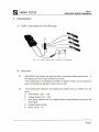
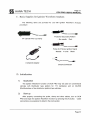
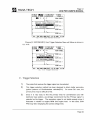
1. Introduction
A. Cable Connection for Oscilloscope
ILL. 3 -1 . Ba si c Cabling f er 4 - Channel Os c illesc e pe
B. Overview
1)
DCN PRO is the world's first scan tool with a 4-channel oscilloscope function . It
can display up to four scope waveforms at a time.
The oscilloscope is not designed for R&D or research in labs , but for analysis of
electric and electronic signals in automo tive circuits .
2)
The Oscilloscope measures and displays DC voltage and up to 100kHz of an AC
signal.
a.
Time division : 25/Ls - 20s
b.
Voltage division 0.1V - 20V
c.
Auto Setup: Adjusts time and voltage divisions automatically according to the
input signal
d.
Display freeze function
e.
Zoom: Up to X 5
Page4
B
Page 5
HANATECH
DeN PRO USER'S MANUAL
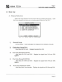
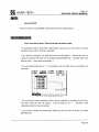
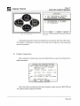
2. Start Up
A. Channel Selection
Select the scope function from the main menu by pressing the [2] key.
PRO then displays the initial menu of oscilloscope function as in ILL. 3-2.
DCN
DIGITAL SCOPE
DUAL AUTO SETUP
DUAL AUTO SETUP
FOUR AUTO SETUP
SCOPE PC INTERFACE
t1 :
ILL.
1)
3-2
Initial
Menu
Displays the signal from CH1
Dual Auto Setup(CH1/CH2)
Displays the signal from CH1 and CH2
Dual Auto Setup(CH3/CH4)
Auto Setup for CH3 and CH4.
together
5)
Oscilloscope
Single Auto Setup(CH1)
Auto Setup for CH1 and CH2.
together
4)
of
User shall adjust the voltage and time divisions manually
Auto Setup for CH1 only.
3)
ENTER: SELECT
General Scope
No Auto Setup .
2)
MOVE
Displays the signal from CH3 and CH4
Four Auto Setup(CH1/2/3/4)
Auto Setup for all four channels.
Displays the signal from CH1 through CH4.
Page 5
B HANATECH
Page 6
DeN PRO USER'S MANUAL
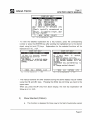
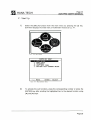
B. Sensor Selection
When you ehoose 2 through 5 from the aboye menu, the Auto Setup menu will
follow . Sinee the voltage level and the output speed of the sensors vary from ea eh
other, you must ehoose the appropriate sensor.
OH AUTO SETUP
1. INJECfOR
2. A. F. S.
3. 02 SENSOR
4. ISC SlEP ~
5. ISC OOTY
6. lR PASE
7. T. P. S.
8. M<\P SENSOR
9. V. S. S.
10. W. T. S.
it :
11. PRWARY IG
12. ALTERNA.TOR
13. c. P. S.
14. 1 TDC SENSOR
15. PLRGE SOLEl'UID
16. PASE SENSOR
17 . SENSOR (O-IV)
18. SENSOR (0-5V)
19. SENSOR (0-12V)
M:NE ENTER : SELECf
ILL. 3-3 Initial Mn.l of Cscill=
F\.Irrtim
Aeeording to the seleeted sensor, DCN PRO will adjust the proper Time and
Voltage divisions, Trigger Level and Trigger Mode for the measurement and
display of the seleeted sensor signa!.
For example,
INJECTOR mode has its default setting as Volt Div:20V
Volt:5V Trig Mode : NORMAL
AIR FLOW SENSOR mode as Volt Div:2V
Trig Mode: NORMAL
Time Div:1ms
Time Div:10ms
Trig
Trig Volt:2V
If you eh ose Dual ehannel Auto Setup menu , the same menu for CH2 sensor
seleetion will follow. For the four ehannels seleetion, CH2, CH3 and CH4 will
follow up.
Page 6
B HANATECH
page 7
DeN PRO USER'S MANUAL
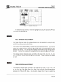
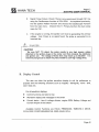
3. Display Format
When the Auto Setup selection is finished , DCN PRO begin to display scope
output as shown below:
9.HOLD
4 .GND
1.CHAN
5.ACDC
ILL.
3. TIME
PAGE 44
3-4.
1) Upper screen portion : Display control menu .
Details are explained in the following section .
2) Center screen : Oscilloscope Waveform display
3) Lower screen : Current set up status .
Details are as shown below.
Page 7
B HANATECH
Page 8
DCN PRO USER'S MANUAL
4. Display Control
You can change the scope waveform display to your preference or purpose
with the display control functions. The functions can be divided into two stages NORMAL and HOlO, in other words, when [O . HOlO] is not selected and when it
selected .
[O . HOlO] activa tes extensive functions for detailed analysis .
A. NORMAL: When [O. HOLD] is not selected
[HOLD] MODE
-
Stops displaying the Scope waveform and shows the detailed menu .
While in the [HOlO] Mode, the signal may be diagnosed in greater detail and other
extensive display output control functions may be performed, Le. Cursor, Trigger
and Zoom.
The details are explained in the following 'S. HOlO: When [O . HOlO] is selected'
section .
SIGNAL INPUT CHANNEL SELECTION
-
OCN PRO supports single (CH1-CH4), dual (CH1/2, CH3/4) and four(CH1/2/3/4)
channel oscilloscope modes. Channel selection menu will be displayed when you
press the [1] key.
1-4. CH1-4 : Signal Input from Channel 1-4. Single Channel
5. OUAl 12: Signal Input from Channel 1 and 2. Oual Channel.
6. OUAl 34 : Signal Input from Channel 3 and 4. Dual Channel.
7.4 CHAN : Signallnput from all Channels . Four Channel.
Page 8
B HANATECH
Page 9
DeN PRO USER'S MANUAL
B.HOLD
4.GHD
'Kij:r;"lll
5.ACDC
2.UOLT
6.TRIG
3 .TIHE
PAGE 44
CH SELECT
••1311- .
2.CH2
3.CH3
4.CH4
.. ... .
. ..... .... . . . . :
,.. .
5 . DUAL 1 2 : .. .. . .....
1-
6.DUAL 34 :...-....:
7.4 CHAN
. '
....111<>
~
'---~
.. ... .
~
:
1."i . . . WII••'''-
ILL. 3 - 5. Channel Select lon
To select the input channel, move the highlight bar using the [.&.] and [.... ] keys
and press the [ENTER] key .
• t'.]I'
VOL T O/V/S/ON ADJUSTMENT
•
-
For Single Channel mode, the voltage division may be adjusted by using the [.&.]
and [.... ] keys after pressing the [2] key.
-
For Dual or Four Channel Mode, choose the input channel for which you wish to
change the voltage division using the [<l1li] and [~] keys or the [ENTER] key after
pressing the [2] key. You will see the highlight move left and right in the bottom
window. You can then change the voltage division by using the [.&.] and [ .... ] keys.
-
The voltage division alternates back and forth in the order of 0.1, 0.2, 0.5, 1.0, 2.0,
5.0, 10.0, 20 .0V as you press the [.&.] and [ .... ] keys . These indicate the voltage
per grid .
11~13
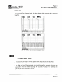
T/ME D/V/S/ON ADJUSTMENT
-
Time division changes back and forth in the order of 25tLs, 50tLs, 0.1 ms, 0.2ms, 0.5
ms, 1 ms, 2ms, 5ms, 10ms, 20ms, 50ms, 0.1s, 0.2s, 0.5s, 1s, 2s, 5s, 10s, 20s per grid as
pressing the [<l1li] and
[~]
keys .
Any duration longer than 0.1sec is called the
Page 9
B
Page 10
HANATECH
DeN PRO USER'S MANUAL
ROLL mode .
_ For Dual and Four Channel mode, the time division of all channels will be changed
together.
2.IJOLT
6 .TRIG
. . . . . . . ..
........
"
.. . . . .
.1I.lml
PAGE 44
. . . . . . . . . . . . . . • ••
.....
......... . .. ............ .
. . .. . . . . . . . ..
. ... . .... .
. . . . . . . . . . . . .. .
T: 2ms :
..
...
·· · · · · · · · · · · · · · · · · · · · · · · ·
1
ILL . 3 - 6. Before Ti me Division Adjustment
B.HOLD
4 . GND
1.CHAN
5.ACDC
T
2.IJOLT
6 .TRIG
n
(2ms)
.1I.liliíl
PAGE 44
n
t.:2~s •
•
'Íe¡."\.,.i.
ILL. 3-7. After Tlme Dlvlslon Ad]ustment
(20ms)
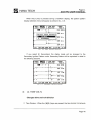
GROUND LEVEL SHIFT
_ The Ground Level may be moved up and down using the [.A] and [T] keys.
_ For Dual and Four Channel mode, the input channel that you wish to move the
ground level must be chosen by using the [..-] and [~] keys or by pressing the
[ENTER] key after pressing the [3] key.
Page 10
B HANATECH
-
Page 11
DCN PRO USER'S MANUAL
On the right end of the display , the inverse triangle icon("') with a small digit next
.
.
.
.
..
.
.. .
.
..
.
..
..
' (lROÜNP~AR~
/
..
.
:'
..
.. ..
. ...
. ... ...............
...... ... ... ..... .. .. .. .... ....
.. .......
. . .
ILL. 3-8. Ground Mark
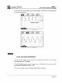
ILL .3 - 9. AC Pattern
AC/DC VOLTAGE CONVERSION
-
The AC and DC voltage scope modes can be switched when the [5] key is pressed .
The default mode is DC voltage .
-
The AC Voltage mode is used for measurement of Alternating Current signal such
as Generator Waveforms (See ILL. 3-9)
-
The current voltage mode is indicated at the bottom of display.
Page 11
B
Page 12
HANATECH
DeN PRO USER'S MANUAL
·'¡1M
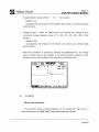
TRIGGER SETUP
- When [6 . TRIG] is selected by pressing the [6] key, the [Trigger Setup] menu will be
displayed.
~.HOLD
~.GND
t
[mnlEfI
T:
3.TIHE
PAGl: ~
I
TRIGGER SETUP
1.S0URCE : CH1
2. t.lODE : AUTO
3.Sl0PE : RISE
lf.lEVEl : 2. OOV
..... POSIT : 25
1
. .
2.VOLT
l.CHAN
5.ACDC
:
:
.. .. . .... .
r.-
. .. . ..
.
1'\.. .T-\.
. . .. . . .. ...... . . .. . .
.. : .. ......:.- . . . .
......:.- .
.. .....
1
Sms
ltllliRlllh"'l.!
ILL. 3- 10. Trl g ger Se tup
1. SOURCE: Changes the Trigger Source in Dual or 4 Channel Mode
Repeatedly pressing the [1] key alternates CH1 ...... CH2 in Dual 1-2 mode, CH3 ......
CH4 in Dual 3-4 mode, and CH1-CH2-CH3-CH4 in the Four Channel Mode.
2. MODE: Changes the Trigger Mode.
Repeatedly pressing the [2] key cycles between AUTO-NORMAL -SINGLE
SHOT -AUTO mode.
Auto Trigger - Continual display of waveform without trigger signal
Normal Trigger - No display waveform without trigger signal
Single shot Trigger - Stops displaying waveform when trigger signal is
nd, and proceeds to [HOlO] mode.
Page 12
B
Page 13
HANATECH
DeN PRO USER'S MANUAL
3. SLOPE: Rising / Falling Trigger Switch
The trigger voltage and its slope must first be determined . [3 . SLOPE] decides
which signal to catch as the trigger : rising or falling voltage as the trigger.
t
* LEVEL: Trigger Voltage Level
Adjust the trigger voltage level by using the [.Á.] and [T] keys
The small triangle icon (,.. or ... ) on the left sida of th,e display indicates the
trigger voltage and slope(See ILL. 3-11)
~
POSIT : Trigger Position
Set the trigger po sitio n where you wish the triggered waveform to start.
can move the position horizontally using the [ .... ] and
mark (Rising :
t or Falling :
[~]
keys.
You
The arrow
t) in the top end of the display indicates the
trigger position and the slope : Trigger Mark (Se e ILL. 3-11)
B.HOLD
l .CHAN
5.ACDC
2.VOLT
6.TRIG
3.TIHE
PAGE 44
.... r .. ~ TRlGGER"ARK "
............ tRIGGER LEVEL · tiiMK ·
ILL . 3-11. T rigger mark
In RolI Mode (Time division longer than 0.1 Sec), there is no trigger level mark
and trigger mark shown in the display. It has no application in the RolI Mode.
PAGE ## : Number of saved pages
DeN PRO automatically records scope waveforms up to 50 frames to its
Page 13
B
HANATECH
Page 14
DeN PRO USER'S MANUAL
internal RAM(automatically deletes on exit).
When [o . HOlO] is selected, waveforms can be saved to OCN's Flash ROM
which can then be transmitted to your PC by using the PC Interface function .
ESC : Exit
Page 14
B HANATECH
Page 15
DeN PRO USER'S MANUAL
ro. HOLD] is selected
B. HOLD: When
[O.HOlD] stops waveforrn display and activates extensive functions for detailed
analysis.
You will see that the menu on the top window is changed .
,.tt:11II
1 . AUTO
5. SAVE
14. GND
2. CURS 3. ZOOlllxl
6. RCLL 7. PAGE 6
t l l l A X IIIIN
. . . . . . . . r -.
'.~~
.'-.......;.
... ....
~-
... ...
~
• L....:...
. . . ..... . . . . .. ........ ...
14 . 9), B 87"
1
xl: 2ms •
ILL. 3 - 12 . HOLO MODE
Grid On/Off
Turns grid on I off
,.tt:1I11
1. AUTO
5. SAVE
4. GND
2. CURS
6. RCLL
3. Z001llxl
7. PAGE 6
IIIAX 1111 N
t
"
1 '
"
0'
...
r.-
. ..
,
. ..
. .. . ,
,..
~-
-
,
..,
I.........r
"
' 1 '
.. , ... , . " , .
..
14.9v B.87v "'í
xl,: 2",s
_IIURnllo,\'.
I LL. 3 - 13. Gr,d Off
Page 15
B HANATECH
Page 16
DCN PRO USER'S MANUAL
'.'lllel
Auto Set-up
Activates [Auto Set-up] function - sets up voltage division automatically in
accordance with voltage input
When the [1] key is pressed, DCN displays 'AUTO SETUP IN PROCESS'
message, and then resumes the scope waveform display.
1 . AUTO
5. SAVE
2. CURS
6. RCLL
3. ZOO"xl
7. PAGE 6
..AX "IN
ILL. 3 - 1 4. Auto Setup in Process
-
In case of high input voltage levels such as Injector or Primary Ignition Patterns,
above message may remain on the display. If this occurs, simply press the [ESC]
key. The scope waveform display will resume .
'U!)....
Cursor
-
Displays the cursor selection menu as shown in ILL. 3-15.
1. CURSOR OFF: Turns of the cursor(s)
2. CURSOR 1: Turns on and moves the solid line cursor
3. CURSOR 2: Turns on and moves the dotted line cursor
4. A + B: Turns on and moves both solid and dotted line cursors
Page 16
B
Page 17
HANATECH
DeN PRO USER'S MANUAL
1. AUTO
5. SAVE
2. CURS
6. RCLL
3. Z001llxl
7. PAGE 6
IIIAX
CURSOR
1.CURSOR OFF
2 . CURSOR A
3. CURSOR B
4.
IIIIN
A + B
....... ....
35 .lv B:.S8v
t
ILL. 3 - 15. Cur s o r
-
When you choose 2, 3 or 4, the cursor(s) will appear as shown below:
1. AUTO
PI!iIj¡b1
5.SAVE 6. RCLL
............ :.. ¡...
3. ZOOlllxl
7.PAGE 6
IIIAX
t.tIN
:¡
.':' :
. .. ~ .¡...
'--
dV : The voltage difference between the horizontal solid line and dotted line.
dT : The time gap between the vertical solid line and dotted line.
x1 : The time division per grid
-
You can move the selected cursor lines using the arrow keys.
... / T
... /
~
: Horizontal line up / down
: Vertical line left / right
The line will move a pixel when you press the key once.
the key will move the line in rapid succession .
-
Continually pressing
In Dual or Four Channel Mode
You can choose the input channel by using the [ENTER] key, and dT and dV
value will be calculated based upon the time and voltage divisions of the selected
input channel. The selected channel will be highlighted in the bottom window.
Page 17
B HANATECH
Page 18
DeN PRO USER'S MANUAL
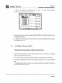
3. ZOOM
Waveform Zoom In / Out
-
Zooms the scope waveform in/out in the horizontal axis.
reducing / increasing the time division value.
It has the same effect as
-
The scale will alternate in increments of x1, x2 and x5 when you press the [3] key.
p. GR I O 1. AUTO 2 . CURS tc."(IlIl~1!!I1
O. GR I O 1. AUTO
2. CURS tc ...mll~&..j
14. GND
f
5. SAVE
6 . RCLL
7. PAGE 6
.
MAX
4. GND
5. SAVE
+
lit I N
.
. • . ..,..,.:.,..,.:
~
,.,..:-
'~
.
.
:.
.
lit I N
l...-.. :
.... . .. .... ... .. . .• .. . .~...
... ~
...
14 .6v B:. 58v
7. PAGE 6
MAX
..
L.-:-~
6. RCLL
- -', --...:.¡ B.58v
1
1
x2:. 2ms
•.
.
xl: slns :
ILL . 3 -17 . ZOOM Xl
O. GR I O
4. GND
ILL .3 - 18. ZOOM X2
1 . AUTO
5. SAVE
tc •.•ml)~~'
2. CURS
6. RCLL
7. PAGE 6
f M A .X
. . . . . . . . . . . . . . . IItIN
. .... ... .... .. , ... .... .. .... .. .. . .. .
.. .... .. ..... ...
"
L---,.,.r-:-:-:c
..-:-:
.. -:-c'
. • ••
'
•••
•
.....::. ~
14.6v B.58if
1
ILL .3- 19. ZOOM X5
DCN has a waveform data save / reload function.
SAVE] and [6 . RECALL] will explain the procedures
-
The following sections [5.
When recorded data is reloaded, press the [2] key. The recorded waveform can
then be displayed frame by frame using the [ .... ] and [T] keys .
DCN records up to
12 frames per slot.
Page 18
B HANATECH
Page 19
DeN PRO USER'S MANUAL
Ground Shift
- Same as section 4.a [NORMAL: When [O .HOlD] not selected] part o
5. SAVE, 6. RECALL
Save wa veform data / Recall saved waveform data
-
-
As explained earlier, DCN PRO automatically records up to 50 frames of scope
waveform data until [O. HalO] is selected.
If [5. SAVE] is selected, the Data Save Slot list will appear.
Choose the slot by
using the [ .... ] and [T ] keys and by pressing the [ENTER] key.
Number keys may
also be used.
-
Used slots are marked
If a used slot(marked by an '
* ')
'* '.
is selected, any old data will be overwritten by
new data.
. GR ID
. GND
1. AUTO
h....iNJI
2. CURS
RCLL
6.
3. ZOOMx1
7. PAGE 6
t M A > < ¡.tI N
1 WVFORM1
2.WVFORM2
3.WVFORM3
4 .WVFORM4
5.WVFORM5
6.WVFORM6
7.WVFORM7
B.WVFORMS
. . .. .......
. . ....
...... ...... ..... ........
........ , . . .
14.6v
.. . .
B.5BV
1
xS: lms :
ILL. 3 - 20. Save Scope Wave form Data
-
The previously saved waveform data may be recalled by pressing the [6] key.
The Save Data Slot list will appear.
A slot marked by an ' *'
indicates a slot
containing data that may be loaded
-
If you want to delete the saved data, select the slot you wish to erase and press
[ERASE] key.
Page 19
B
Page 20
HANATECH
DeN PRO USER'S MANUAL
· GR Io
1. AUTO
· GND
5. SAVE
2. CURS
nll:ill..
3. ZOOt.lxl
7. PAGE 6
t
*1. WVFORt.ll
2. WVF ORt.I 2
3 . WVF ORt.I 3
4 . WVFORt.l4
5.WVFORt.l5
6.WVFORt.l6
7 . WVFORt.l7
8 . WVFORt.l8 ............ .
"--....,...........,..---.,._,.....-1
14.6v B .58~""i
xS: lms •
ILL. ) - 2 1 . Recall Saved Waveform Data
c. Oscilloscope Help
When [HElP] is pressed during the scope waveform display, the help selection
menu will appear as illustrated below:
· GR ID
1. AUTO
2. CURS
3. ZOOt.lxl
· GND
5. SAVE
6. RCLl
7. PAGE 6
t
1 . Scope He I p
2. Show Standard
3. Hide Standard
..... ,
.. .... . ..
. . .. ...... ..
.
.
.
.. .........
. . . .......
. . ...... ..,
'
. ....... . . .. . ....... . . .
xl:B.Sm •
a:IIoI.WiII.l.:lilt::IIlI ..................................................................................................................J
IL L .) - 22. Osci lloscope He l p Menu
1)
-
Scope Help
Select [1. Scope Help] to view key explanations for the functions explained in this
chapter. You will see the submenu as shown in IlL. 3-23.
The key explanation consists of 13 categories. They are as follows;
For NORMAL Mode : CHAN , VOL T, TIME, GND , ACDC, TRIG , HElP
For HOlD Mode : GRID, AUTO, CURS, ZOOM, SAVE, RCll
Page 20
B HANATECH
Page 21
DeN PRO USER'S MANUAL
~ .
TIME : ADJUST
GND : MOVE GROUNO
ACDC : SELECT AC/DC
. TRIG : TRIGGER MODE
. .HELP : FRE;EZE DI~PLAY
1his tunetion 15 des1gned only
tQr
.
51 gna1 s typ1 cally eneountered on
eehicle . ¡t sUQPorts single, dual
and tour ehannér
ILL. 3- 23 Key Explanation - menu
To view the detailed explanation for a key function, press the corresponding
number or press the [ENTER] key after scrolling the highlighted bar to the desired
object using [ .... ] and [T] keys .
Explanations for the selected functions will be
displayed as in ILL . 3-24.
1.
SCOPE KEY HELP
CHAN : SELECT CHANNEL
If k~ 1 is p~e~sed, ehannel
~erect10n box W1 Ir be
d1spr~ed.
.
T e e a nel 15
CHTI2
DUAL
7'4,
L
CHANN
<--> :
MOVE
e eeted aman g
1~!~4
and FOUR
ESC: RETURN
1/ 13
ILL. 3-24 Key Expl anation - l. CHAN
-
SCOPE KEY HELP
2. VOLT : ADJUST VOLT DIV
menu
i s marked,
.
.
1 S u~ed to ad] ust vo lt/ dw .
.
At t e bottom screen ... VO.llt/d1bV
of t e marke d ehanne I W1 11
e
ehanged.
LEFT/RIGHT key and ENTER key is
used
to ehange marked ehannel.
If
2. VOL T
VP/ DOWN key
<--> :
MOVE
ESC: RETURN
2/ 13
ILL . 3- 25 Key Explanation - 2 . VOLT
The manual contents for other functions during the aboye display may be viewed
using the [ .... ] and [~] keys.
Pressing the [ESC] key will bring you back to the
upper menu .
When you press the
[~]
key from aboye display, the next key explanation will
follow as in ILL. 3-25.
2)
Show Standard (Pattern)
a.
This function is designed for those new to the field of automotive sensor
Page 21
B HANATECH
Page 22
DeN PRO USER'S MANUAL
analysis.
b.
By showing the general patterns of sensor output, it provides the user
with the proper voltage/time division and the key feature of eaeh sensor
and aetuator.
c.
Choose [2. Show Standard] from the seope help menu to view a standard
pattern .
. HOLD
· GND
1.CHAN
5 . ACDC
2 .UOLT
utll:mJ
3.TIME xl
PAGE 44
t
Standard Pattern
1.
Injector
Ai rfl ow Sensor
02 Sensor
Ise Sep Motor
TR Base
MAP Sensor
Pr im. Ignition
2.
3.
4.
5.
6.
7.
.
.
..... . ... .. . . .. ....
. ..
. ....... . .. ..... . .. ...
t
....................................................................................... ...............1
ILL .)-26 . Standa r d Pattern Menu
d. Seleet a sensor/aetuator from the menu . The standard pattern of the
selected sensor/aetuator will appear on the right side of the main window
as shown in ILL. 3-26 .
B.HOLD
4.GND
t
1.CHAN
5.ACDC
2.UOLT
6 .TRIG
:
............ ..... . ....... . ..
3 .TIME
PAGE 27
I nj ector
(lms, 2BU)
.
· . . . . . . . . . ... .....
:
·........
. ..... . .
:
:
..... ... ......
.........
:
T::l~s
:
..... . ...
t~
[Feature]
Inject Time
Surge Volt
Feedback
Fuel Block
1.Ii;iRIIII"Á'"
ILL. ) - 27. Standard Pattern
e.
To hide the standard pattern, press the [HELP] key and then ehoose [3 .
Hide Standard] .
Page 22
B HANATECH
Page 23
DeN PRO USER'S MANUAL
5. Print Output
Prints the scope pattern . The current scope pattern display can be printed.
The saved waveform data may also be printed by loading it from the memory slot.
A. Print current display
When you wish to print the scope pattern while testing the sensor/actuator with
your OCN PRO, hold(freeze) the pattern display by pressing the [O] key first.
Then press the [PRINT] key.
~.HOLD
I't .GND
1.CHAN
5 .ACDC
2.VOLT
6 .TRIG
3.TIHE
PAGE ~
Connect Cable
. ~r---..:..
Enter : Pr i nt
.
:'- .: l. .. : ~ .: .I. .. : ~ .
. . Start Page( .... ) 1
. . End Page (U) 44 ."
.-..:,
1
, ~~
, ,.,.,
,,,.,.,
, :",,!
, ~=""
.
T:
,,.,.
, ,.,..,-,::="",,.,.,.,.,¿,j
' ",:" ~
" , : ,, ~ "" . ...
5ns .
ILL , ) - 28, Pri n t Menu
Since OCN PRO automatically records the scope patterns for up to 50
frames(pages) until you press the [O.HOlO] key, the page you wish to print must
be selected as shown in IlL. 3-28. In the above example, the user selected to
print all pages(1-44).
You can change the start page with the [ .... ] and
[~]
keys,
and the end page with the [.a.] and [T] .
When ready, press the [ENTER] key to print.
B. Print saved pattems
load the saved waveform data from the memory slot : [O.HOlO]
-+
[6 .RCll]
'Connect Cable' message will follow . The individual page cannot be set here.
Since it is necessary to scroll back and forth to switch from frame to frame, only
the current frame(page) may be printed at a time.
Page 23
H HANATECH
page 24
DeN PRO USER'S MANUAL
. GRIO
. GNO
1. AUT
5. SAV
2. CURS
(ítltitJ..
3. Z001llxl
7. PAGE 6
t
ConneGt Cable
Enter : Pr i nt
••
o
..
.
,
...
ILL . 3-29. Print recall saved data recall
C. Print
DeN PRO initializes the printer when the [ENTER] key is pressed .
. HOLD
l.CHAN 2.VOLT 3.TIHE
.GND
5 .ACDC 6.TRIG PAGE 44
t
I NI TIALI ZI NG
,
.........
ILL. 3 - 30. Printer Initialize
If the printer initialization fails, an initialization error message will appear.
. HOLD
.GND
l.CHAN
5.ACDC
2.VOLT
6.TRIG
3.TIHE
PAGE 44
t
PRINTER INITIAL ERROR
CHECK PRINTER
ILL. 3-31 . Printer Initializati o n Error
Page 24
B
page 25
HANATECH
DeN PRO USER'S MANUAL
If all conditions are OK, DeN PRO will begin printing.
~.HOLD
~.GND .
1.CHAH
5.ACDC
2.UOLT
6.TRIG
3.TIME
PAGE 44
t
PRINTING ........... · ..
G
T: 5.ms :
Page 25
B HANATECH
Page 26
DeN PRO USER'S MANUAL
Chapter 4. Multimeter
1.
Introduction
27
2.
Voltmeter
29
3.
Outy Cycle
30
4.
Frequency
32
5.
Show AII - Volt Outy Freq
33
6.
Battery Voltage / Current Meter
33
7
Help Message
34
Page 26
B HANATECH
Page 27
DeN PRO USER'S MANUAL
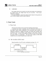
1. Introduction
A. Cable Connection for Multimeter Function
B. Overview
1)
Modules
The multimeter module supports Volt, Outy Cycle, Frequency and Current
Ampere measurements.
2)
Measurable Range
a.
Voltmeter : OC ± 100V
b.
Outy Cycle : 0 - 100%
C.
Outy = Low / (HIGH + LOW) x 100 (%)
d.
Frequency : 5Hz -
e.
Current Ampere : ± 128A
100kHz
Page 27
B HANATECH
Page 28
DeN PRO USER'S MANUAL
c. Start Up
1)
Select the [MUL TI] function from the main menu by pressing the [3] key.
DeN then displays the initial menu of multimeter module as ILL. 4-1.
ILL . 2 - 2 Main Menu
SCOPE KEY HELP
-;~
3. FREQUENCY
4. VOLT DUTY FREQ
5. BATTERY VOLT CURRENT METER
i 1 : MOVE
ENTER
SELECT
ILL . 4 - 1 Mu l t lmeter menu
2)
To activate the sub functions, press the corresponding number or press the
[ENTER] key after scrolling the highlighted bar to the desired function using
[.] and ['Y] keys.
Page 28
B HANATECH
Page 29
DeN PRO USER'S MANUAL
2. Voltmeter
A. Range
OC voltage of o
-
± 150V with probes connected to CH1 and CH2.
B. Display Fonnat
1)
As shown in ILL. 4-2, the large digits in the center ' of the display indicate
current voltage.
2)
For each channel , the Maximum and Minimum voltage values are indicated in
the lower lines . The MaxlMin values can be reset by pressing the [ENTER]
key.
VOLT METER
RANGE : -150v -
lmI
13 • 4
MIN : O.OOv
lmI
+150v
MAX : 13 . 5v
2 • 66
MIN :2.08v
_. 2 ..!''!y_ _ 3.FRQ
MAX : 3.26v
4.ALL
5.AMP
ILL. 4 - 2 Volt Meter
3)
From the menu in the bottom window, you can choose other multimeter
function by pressing the corresponding number key.
return to the upper menu to change the mode .
It is not necessary to
a.
[2. DUTY] : Changes to Outy Cycle mode
b.
[3 . FREO] : Changes to Frequency mode
C.
[4 . ALL]: Changes to Show AII mode (Volt + Outy Cycle + Frequency)
d.
[ENTER] : Resets Min . and Max. values
Page 29
B HANATECH
4)
Page 30
DeN PRO USER'S MANUAL
Calibration
If the voltage values are not equal to zero when the pro bes are not aUached to
any voltage source, the voltage output may not be correct. If this occurs,
calibration is necessary .
For proper calibration, connect the probes of each channel to the ground port
of the 4-channel adaptor and then press the [O] key.
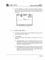
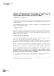
3. Duty Cycle
A. Duty Cyc1e
The Duty Cycle function can be used for the rectangular type signals.
In example, Duty Cycle is especially useful for checking the performance of
Idle Speed Control motors, especially for the duty-control type vehicles as
opposed to frequency or voltage control type. The engine load increases when
accessories such as air conditioner, power steering or other power consuming
items are running. The ISC motor therefore increases its active time to increase
the engine RPM for compensation . The Duty Cycle module of DCN PRO
enables the user to check this performance of ISC motor.
B. The waveform ofISC motor
General waveform of an ISC motor is rectangular as shown in ILL . 4-3 .
HIGH Vollage
LOW voltaoe
Duralion 01 High Vol!
Low voll duralion
Duralion 01 One Cycle
ILL. 4-3.
Typica l shape 01 Ise molor signal
Page 30
B HANATECH
Page 31
DeN PRO USER'S MANUAL
The low voltage indicates that the Ise motor is running . The duty cycle is
calculated by dividing the duration of low voltage by the duration of one cycle. The
resulting duty cycle is expressed in a percentage.
DUTY CYCLE
=
Duration of LOW voltage
Duration of one cycle (LOW+HIGH)
c. Display Format
1)
As shown in ILL. 4-4, big digits in the center of the display indicate the duty
cycle .
2)
Duration of LOW and HIGH voltages are indicated on the bottom of the
screen in milliseconds.
Maximum and Minimum ratios are also indicated just below Low / High values.
DUTY CYCLE
RANGE : 0.0""<; -
100%
CHl
LOW : 10 . 5 ms
MIN :49.7 %
HIGH
MAX
: 1 0 . 6ms
:49.7%
ENTER : MIN / MAX RESET
1. VOL T 3. FREQ 4. ALL 5. AMP 6: CH
ILL. 4- 3 Duty Cycle
3)
Pressing the [ENTER] key resets the Minimum and Maximum values
4)
From the menu in the bottom window, you can change the multimeter mode
by pressing the corresponding number key .
5)
You can change the signal input channel by pressing the [6] key.
Page 31
B HANATECH
Page 32
DeN PRO USER'S MANUAL
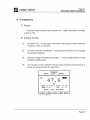
4. Frequency
A. Range
Frequency meter measure values between 5Hz - 100kHz with probes connected
to CH1 or CH2 .
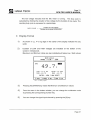
B. Display Fonnat
1)
As shown in ILL. 4-4, big digits in the center of the display indicate measured
frequency in hertz or kilo hertz.
2)
The active channel is highlighted . The signal input channel may be changed
by presslng the [6] key.
3)
Frequency range is indicated at the bottom .
Press the [ENTER] key to reset
the MAX and MIN values .
4)
You can also run the multimeter and duty cycle module by pressing the [1] or
[2] key without returning to the upper menu .
FREQUENCY
RANGE : 1.0Hz - 100Khz
CH1
47.6
Hz
LOVV : IO . 5 ms
MIN : 47 . 6 %
HIGH :lO.6ms
MAX
: 47.6 %
ENTER : MIN / MAX RESET
l.VOLT 2.DUTY 4.ALL 5.AMP 6:CH
I LL. 4 - 4 Frequenc y
Page 32
B HANATECH
Page 33
DeN PRO USER'S MANUAL
5. Show AII Mode - Volt
Outy Freq
DeN displays voltage(2), duty cycle and frequency on one by selecting the
[4. Volt Duty Freq] module from the multimeter menu as shown in ILL. 4-5 .
In this module, it is not necessary to select each module to view these values
separately.
To go back to the upper menu, press the [ESC] key.
VOLT/ DUTY / FREQ
MAX: 13.5V
CHl
13.4
v MIN: 13 . 4V
CH2
1.50
v MIN: 1.50V
CH2
49.8
MAX : 49.8%
% MIN : 49.7 %
CH2
47.6
MAX: 47.6Hz
Hz MIN: 47.6Hz
MAX:
3.81V
ILL. 4-5 Show All Mode
6. Battery Voltage / Current Meter
Measures battery voltage and ampere current.
The current Probe must be connected to the (+) or (-) terminals of vehicle
battery for measurement.
BATTERY VOLT / CURRENT
RANGE : -lOOAmp - +lOOAmp
DD
13 • 4
MIN: 13.4v
lmI
MAX: 13. 5v
1 • 10
MIN:-O.17A
l.VOLT 2.DUTY
MAX: 2.20A
3.FREQ 4.ALL
ILL . 4 - 6 Battery Vo ltage and CUrrent Ampere
Page 33
B HANATECH
Page 34
DeN PRO USER'S MANUAL
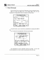
7. Help Message
Press the [HELP] key to view the Key Explanation for each multimeter function.
When you press the [HELP] key in the Voltage Meter mode, the key
explanation for Voltage Meter function is displayed as shown below:
MULTI METER KEY HELP
1 : VOLT METER KEY HELP
2,3,4,5
:
Select
other
function
: Adjust Zero Volt
o
ENTER : Reset MIN/MAX
This function is designed for
DC
-150
+150
voltage
measurement.
It can be changed to the DUTY
METER or FREQ METER at one
time.
-: tv'OVE
ENTER
RETURN
l/5
ILL. 4·7 Key Explanat,on tor Voltmeter
For each function, you can view the key explanations by pressing the [HELP]
key.
ILL. 4-8 shows the key explanation of the Duty Cycle function.
MULTI METER KEY HELP
¿.
J.}Jl"Y
Mt:!"ta{
~y
.tili.LP
1,3,4,5 : Select other functian
6
: Olange ~t channel
ENTER : Reset Mm MAX
IHighl
I
I.i::1w
= low / (high+low) * 100 (%)
'!he Dl7I'Y is the$rcentare of the
duratian of hi
signa in one
cycle.
It can be changed to the VOLT
MRI'ER or FRElJ MRI'ER at ane time.
- : tv'OVE
ENTER : RETURN
2/5
Dl7I'Y
ILL. 4·7 Key Explanation tor Voltmeter
Key explanations for all five multimeter modes are provided.
the key explanations on other functions by pressing the
[~]
or
[~]
You can view
keys .
Page 34
B HANATECH
page 35
DeN PRO USER'S MANUAL
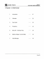
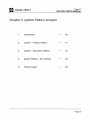
Chapter 5. Ignition Pattern Analysis
1.
Introduction
36
2.
Ignition - Primary Pattern
41
3.
Ignition - Secondary Pattern
51
4.
Ignition Pattern - DLI Vehicles
55
5.
Printer Output
63
Page 35
B HANATECH
page 36
DeN PRO USER'S MANUAL
1. Introduction
A. What is an Ignition Pattem?
An Ignition Waveform is a graphical representation of voltage fluctuations in a
recurring procedure - the high voltage from the secondary ignition coil which is
created when the electric power in the primary coil that was fuliy charged by power
TR collapses when the power TR is turned off. This produces a spark over the
gap of the spark plug in the cylinder, which is used for combustion of the air-fuel
mixture.
DCN PRO can analyze both Primary and Secondary Ignition Waveforms.
B. Purpose ofIgnition Pattem Analysis
The Ignition Waveform Analysis function of the DCN PRO is to provide an
accurate visual representation of ignition waveforms to enable the user to analyze
the possible causes of problems within the ignition system.
By designating X(horizontal) axis for time and Y(vertical) axis for voltage, the
change of voltage in relation to elapsed time during the spark-ignition sequence
can be graphed as a waveform. Waveforms have typical characteristics of height
and duration that can be influenced by various factors.
Since each of these factors brings about a noticeable change in the ignition
waveform, the cause of a malfunction can be traced by analyzing the transformed
waveform in reverse.
Page 36
B HANATECH
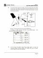
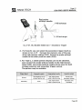
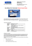
c.
Page 37
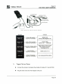
DeN PRO USER'S MANUAL
Basic Supplies for Ignition Waveform Analysis
The following items are provided for use with Ignition Waveform Analysis
procedure:
--~:
Probe.forSecondary Pattern
#1 Cylinder Pick-up Clamp
- No needle .
Red .
~---~~
Probe for Primary Ignition Signal
- Needle.
4 units.
Black .
.-.
(E ~ _ _.....
4 Channel Adaptor
Ground Connector
D. Initialization
1)
Application
The Ignition Waveform function of DCN PRO may be used on conventional
vehicles with Distributor type ignition for 1-6 cylinder(s) and on DLI/DIS
(Distributorless or Non-distributor ignition) type vehicles.
2)
Start-up
After properly connecting the probe, clamp and other cables, turn on DCN
PRO and begin the Ignition Waveform function by pressing the [4] button. Cable
connections are explained in detail in the next section .
Page 37
B
Page 38
HANATECH
DeN PRO USER'S MANUAL
IGNITION
1. DLI
2.
DISTRIBUTOR 6 CYLINDER
PC INTERFACE
ENTER : SELECT
i J : MOVE
ILL. 2 - 2 Main Menu
ILL. 4 - 1.
Function
Initial
Menu
of
Ignition
Pattern
The ignition type and number of cylinders can be chosen from the initial menu.
The default is 'Distributor 4 Cylinder' since they are the majority of the passenger
cars on the market.
E. Cable Connection
After selecting a vehicle type, press the [HELP] key to view the instructions for
cable connection.
CABLING FOR IGNITION PATTERN
CH1: Probe wlth needle to the
negative line of Primary
Ignition Coil
CH2 : Probe without needle to
the
ignition coil center code
or
to a certain cylinder
CH3: #1 Probe to the cylinder
#1
Not used for DLI
+-+ : MOVE
RETURN
ESe
ILL. 4 - 2. cable Connectlon I ns tructlon
When the cable connections have been properly made, press the [ENTER] key.
The ignition pattern display will follow.
Page 38
B
HANATECH
Page 39
DeN PRO USER'S MANUAL
Probe With Need le
Basi c Cabling for I gnition Pattern Analysis
Vehicle
Ignition Coil
Primary Side Negative Une
Center Cable
Ignition Coil <-+ Distributor
High Tension cord to Cyl #1
High Tension cord of (-)
discharge for DLI
Battery Une (+ or-)
Any metal part of the vehicle
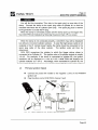
1)
Trigger Pick-up Clamp
•
Connect the clamp to the Spark Plug Cable of Cylinder #1 : See NOTICE
•
Plug the other end to the 4CH adaptor CH3 port.
Page 39
B HANATECH
page 40
DeN PRO USER'S MANUAL
You will find the inscription 'This side to the spark plug' on one side of the
clamp. Connect the clamp to the spark plug cable of cylinder #1 so that the
inscribed side faces the #1 cylinder spark plug. The spark plug that is nearest
to the generator is usually the #1 plug.
When the clamp is connected properly and the clamp picks up the trigger well,
then DCN PRO will indicate it by flickering the ground mark ( 'Y ) on screen .
When the clamp is not connected properly, a waveform may still be displayed
but without or incorrect cylinder numbers. In case the high tension cable is not
available or the #1 cylinder doesn't ignite, the clamp should be connected to the
spark plug cable of the other cylinder. The ignition order will then be
determined.
DCN PRO recognizes the cylinder to which the trigger pickup clamp is
connected to be Cylinder #1 . The ignition order of 4-cylinder engines is usually
1-3-4-2. For example, if the clamp is connected to cylinder #3, the ignition
waveform will be displayed in a row as 3-4-2-1 while DCN still displays the
cylinder indicator as 1-3-4-2. Accordingly, when connected to cylinder #2, the
2)
Primary Ignition Signal
•
•
Connect the probe with needle to the negative (-) line of the PRIMARY
ignition coil
Plug the other end to DCN PRO's channel 1 port
[) s ~ib ulOf
Genter Cede
ILL . 4 - 3 . Cable Co nnection fo r Primary Ignition Pattern
Page 40
B HANATECH
Page 41
DeN PRO USER'S MANUAL
2. Ignition - Primary Pattern
A. Primary Ignition Waveform Analysis
1)
Pattern Display
When the probes are connected properly and DCN PRO receives proper signal
from the vehicle, the Primary Ignition Pattern will be displayed as ILL. 4-4.
3.MOVE
PAGE 7
PEAK DUELL
1.PRIM 2.TIME VOLT
4.CYLN . S.DISP
. . .6.POSITIVE
0-3-4-2
~ . HOLD
36BV 33
%
327V 33
%
339V 33
%
331V 33
%
3.MOVE
PAGE
NO SIGNAL INPUT
CHECK CABLE CONNECTION
2ms SBV RPM:
BAT:
B.BV AMP:
B.BA
ILL. 4 - 5. Error
2)
Error
In case of improper cable connection or signal pickup failure, an error message
as shown in ILL. 4-5 will appear.
a.
Improper Cable Connection : Check the cable connection
Page 41
B HANATECH
&
Page 42
DeN PRO USER'S MANUAL
b.
Signal Pickup Failure: Check if there is any signal input through CH1 line
using the Oscilloscope function of DCN PRO. As explained previously,
end the Ignition Pattern function and choose the Oscilloscope Function
from the main menu . Choose the [11 . Primary IG] from the Auto setup
menu for CH1 .
C.
If the engine is running , the ignition coil must be generating the primary
voltage. And if there is no signal found, the probe is connected to an
incorrect line.
DANGER
CAUTIONI
Be sure NOT TO attach the probe needle to any high tension cables
attached to the ignition plugs or the center cord that connects the distributor
and ignition coil. The voltage of these lines may reach up to 50,OOOV. It is
extremely dangerous to attach the probe needle to such high voltage lines.
B. Display Control
The user can tailor the ignition waveform display to suit his preference or
purpose with the following functions such as magnify / demagnify, move / shift,
save / load, etc.
For all waveform displays,
•
Control functions are listed on top
•
Waveform display and messages in the center
•
Current status - time & voltage division , engine RPM, Battery Voltage and
Current Ampere in the bottom.
Available Control Functions are HOlD, PRIM/SCND, TIMENOl T, MOVE,
CYlN, DISP, POSITIVE/NEGATIVE, GRID, SAVE, RClL.
Page 42
B HANATECH
Page 43
DeN PRO USER'S MANUAL
•
Umited lCO space prohibits listing all
functions at once.
Available while dlsplaying
Pattem
The function selection procedure can
be summarlzed as illustrated on the
righí.
RECALL
HOLO
SAVE
GRID
With regard to the operational flow, the
functions have been divided as follows:
PAGE
Those functions that are available while
the pattems are being displayed will
always appear.
MOVE
The save and recall functions that are
usable only when the pattem display is
stopped will appear when the operation
is on hold.
DISPLAY
1)
Available On
HoId
POSITIVElNEGATIVE
[O. HOLO]
Holds the waveform display and displays extensive control
functions
o
Before [O.HOlO] is selected, the functions
O.HOlO, 1.PRIM / SCNO, 2.TIME VOLT, 3.MOVE, 4.CYlN, 5.DISP, 6. POSITIVE
/ NEGATIVE are listed
o
When [O.HOlO] is selected, the functions
O.GRIO, 1.PRIM / SCNO, 2.TIME VOL T, 3.MOVE, 4.CYlN, 5.DISP,~
SAVE, 7. RCll 8. PAGE will be shown . These functions are available when
the display is paused. Notice that only functions No. O, 6, 7 and 8 are changed .
2)
[1.PRIM]
Primary Ignition pattern
~
Secondary Ignition Pattern
Page 43
B
Page 44
HANATECH
DCN PRO USER'S MANUAL
When the [1] key is pressed during a waveform display, the ignition pattern
display selection menu will appear as shown in ILL. 4-6 .
3.HOUE
PAGE 4
PEAK DUELL
F.---;:====:C~===;-::3~3Ru31J 33 ;.:
Select Input Pattern
1.
PR I MARY
327U 33 ;.:
2. SECONDARY
337U 33 ;.:
3291J 33 ;.:
2ms SBIJ RPH:1BBB BAT: 13.3U AHP: 27.4A
ILL . 4-6 Input Pattern Se l ection
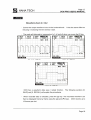
If you select [2 . Secondary], the display mode will be changed to the
Secondary Ignition Pattern mode . Secondary Pattern will be explained in detail in
the following sections.
1_"\11111
2. TI HE IJOLT 3.HOIJE
4 .CVLN . S ..DISP
PAGE 4
. .6.POSITIIJE
D -3 - 4 PEAK SPRK
JI
¡.¡~ ...
12kIJ 4.6m
~ . HOLD
y'
J
~
1"'"
~
......
~
llkU 1.8m
I
i'
12kU 1.8m
JI
r
........
2ms
¡'
llkU 1.7m
1kIJ RPH :1BBB BAT : 13 .4U AHP :-19 .7A
ILL. 4 - 7. Secondary Ignltlon Pattern
3)
[2 . TIME VOL T]
Changes time and volt division
o
Time Division : When the [ .... ][ ~] keys are pressed , the time division increments
Page 44
B HANATECH
Page 45
DeN PRO USER'S MANUAL
change between values of O.5ms
~
1ms
~
2ms per grid .
Default = 2ms
Consequently, the change of time division al so serves as a horizontal detail
control function
o
Voltage Division : When the [ .... U... ] keys are pressed , the voltage division
increments change between values of
1V ~ 2V ~ 5V ~ 1OV ~ 20V ~ 50V ~ 100V
per grid
Default = 50V
Consequently, the change of volt division also serves as a vertical detail
control function
o
When the procedure is paused by pressing the [O](HOLD) key, the voltage
control function will not be available in the primary ignition waveform mode .
Voltage control is still available in the secondary waveform mode .
. HOLD 1 .PRIM ,.
I
.CYLN
5.DISP
6
.POSITIVE
. . . .,
..
101- 3 - 4 -
3.MOVE
PAGE B
PEAK DUELL
327V 33 /:
RPM:IBBB BAT: 13 .2V AMP: -23 .4A
ILL . 2-9. Time and voltage d i vision adjustment
4)
[3 . MOV]
Moves the waveform
The waveform being currently displayed can be moved left / right and up /
down by pressing the [ .... U~U .... U... ] keys after pressing the [3] key.
Page 45
B HANATECH
Page 46
DCN PRO USER'S MANUAL
B.HOLD 1.sam 2 .TH1E l,IOLT
.Cx'LN 5.D[SP 6 .POSITJUE
H-
3 - 4 - 2
-..-
,
PAG[ 4
PEAK SPRH
J.
12kU '1 .6111
~
....
~
1
1 111\\1 1.8rA
j
~
r'12k\I 1.8111
.--
~
2hs
11\\1
RPH:I~80
r--..J
1"111\\1 1.7111
BAT: 13.4V AHP:-19.?A
ILL . 4 · 9 . I gn1t1on Pattern Move
5)
[4. CYL]
Selects a cylinder in single(individual) waveform display mode
o
For the 4-cylinder distributor type engine, the waveform of cylinder #1 will be
displayed first. Waveforms of other cylinders are to be displayed in turn when
the
[~]
or
[~]
keys are pressed after pressing the [4] key.
As explained before,
the firing order of most 4-cylinder engine is 1-3-4-2. As for 5 or 6 cylinder
engines, the user needs to enter the firing order separately.
o
In the waveform display, the cylinder number is highlighted as 8-3-4-2. As the
[~]
key is pressed , the waveforms of the other cylinders will be selected in turn,
1-§-4-2, 1-3-9-2 and 1-3-4~.
6)
For 3-cylinder engine, the sequence is 1-3-2 .
[5. DISP]
Changes Display mode to Single, Parallel Waveform or Bar Graph
o
SINGLE : Single display that shows a single waveform per cylinder (ILL.4-1 O)
Page 46
B HANATECH
o
Page 47
DeN PRO USER'S MANUAL
PARALL : Parallel display that shows waveforms of multiple cylinders
O BAR GRAPH : Displays the maximum voltage of cyl inders by histogram and
numerical values .
Dwell Angles of each cylinder are displayed together.
1.PRIH 2.TIHE VOLT
6.POSITIVE
D- 3 - 4 - 2
~ . HOLD
4 .CYLN
325V
325V
329V
327V
~
-------
l'
3.HOVE
PAGE15
33x
l'
33x
l'
33x
l'
33x
2ms 100V RPH:l000 BAT: 14.0V AHP: 27 .311
I LL.4 - 1 1 . Bar Graph Dl s pl ay
7)
[6. POSITIVE / NEGATIVE]
Selects the discharge polarity.
Only used for DLI ignitions .
8)
[O. GRIO): When on 'HOlO'
Toggles grid On / Off
1.SCND 2.T1ME UOLT 3.HOUE
4·CYLN . 5.D[SP
6 .SAUI. 7.RCLL 8.PAGE15
.
.
..... .~ :.3 . - . 4.: ~. • .... :
..... . P.~~.
sm..
: ~¡ : : :: :
:··c.. .j ···f :· ··· n~ l : 6~·
------~
·· ·· ~-.....·..r
·· ....
.....
.. . ; . .. . ; . .. ; ..... . .. ; . .. . ,"Jt:_' . . ; . . .. : .. ,; " . : . ... ;.
~ T
Ij"'
:
J..Zk\I 1.7~
..
.:.~ .....~~ ..&.!:I .:. ~~~ ..!lfJI.:... n.:.~~ OOf .~ .. lJ·Jlft
ILL. 4· 12. Grid On
Page 47
B HANATECH
9)
Page 48
DeN PRO USER'S MANUAL
[6. SAVE] : When on 'HOlO'
Saves recorded waveform data
This function is the same as explained in Oscilloscope section . DeN PRO
records waveform data up to 50 frames . You can review the recorded data by
selecting [8 . PAGE]
The waveform data will be erased when resuming the waveform display unless
it is saved to DeN PRO's memory. This [SAVE] function must be used to save
the recorded data. The saved data may still be downloaded to your pe .
Select the memory slot to save the data and then press the [ENTER] key.
Used slots are marked with an '
* '.
2.TIME VOLT 3 .MOVE
7 .RCLL B.PAGEl5
l.IJVFORMl
*2.WVFORM2
3.WVFORM3
4.WVFORM4
5.WVFORM5
6.WVFORM6
7.WVFORM7
B.WUFORMB
.....•... .•. 12kV.. 1, 7ril .
• llkV 1.BriI
2ms 5kV RPM:lBBB BAT: l3.3V AMP: ll.BA
ILL.4 - 13. Recorded Wavefo rm Data Save
10)
[7. RCll] : When on 'HOlO'
Recalls the previously saved waveform data
o
DeN PRO can store up to 8 waveforms in its memory.
Refer to the paragraph
9 to see how to save recorded data.
o
8 memory slots will be listed as [#.WVFORM#] (they can not be renamed), when
Page 48
B HANATECH
page 49
DeN PRO USER'S MANUAL
[7. RCll] is selected by pressing the [7] key.
waveform data will be marked with an '
The slot which contains
* '.
3.HOVE
8 .PAGE1S
• PEAK SPRX
::w-:,........
1.WVFORHl
*2.WVFORH2
3.WVFORH3
4.WVFORH4
S.WVFORHS
6.WVFORH6
7.WVFORH7
8.WVFORH8
•
o
•
.......................
..
...•....•.... •.12kV.. 1, 7m ..
• l1)(V I.Bm
.. · ······· · ··· ········ ·12kVbSm
2ms SkV RPH:IBBB BAT: 13.3V AHP: 11.BA
ILL. 4 - 14. Saved Wavef o r m Data Recall
o
Choose the memory slots by pressing [ENTER] after selecting the slot by using
the [A] and [T] keys.
O To delete the saved data from the memory slot, press [ERASE] after locating
the highlight bar on it. ·
11)
[8. PAGE]: When on 'HOlO'
Reviews the temporarily recoded waveform data
O OCN PRO automatically records waveform data up to 50 frames and repeats
this process [O .HOlO]. is chosen.
O You can review the recorded waveform data by pressing the [A] or [T] keys .
O The data is recorded temporarily and will be removed when you press the [ESC]
key.
To preserve the data for future use, choose [6.SAVE], and save the data to
OCN PRO's internal memory.
Page 49
B HANATECH
Page 50
DeN PRO USER'S MANUAL
c. Primary Ignition Pattem of 5 or 6 cylinder distributor type
engmes
While the ignition(firing) order of 4 cylinder engines is 1-3-4-2, the firing orders
of 5 or 6 cylinder engines may differ. It is therefore necessary to manually enter
the firing order for 5 or 6 cylinder engines. AII other procedures remain the same.
1)
o
How to input a Firing Order
The message to input the firing order will be shown when [Distributor 6 (or 5)
cylinders] is selected from the engine type selection menu as in ILL. 4-15 .
Default order for 6 cylinder engine is 1-2-3-4-5-6. If the vehicle's firing order
differs from this, it will be necessary to enter the correct firing order.
B.HOLD 1.PRIH 2.TIHE VOLT
4.CYLH 5.DISP 6.POSITIVE
3.HOVE
PAGE
5 CYLIHDER PRIMARY IG
B.HOLD 1.PRIH 2.TIHE VOLT Clli 11'1:11
4.CYLH
PAGE24
. . 5.DISP
. . .6.POSITIVE
0-2-3-4 5
PEAK DIJELL
~,
.,
INPUT FIRING ORDER
1-2-3-4-5
~,
~.......,
..
"'--..
~
"
2ms 5BV RPH:1BBB BAT: 13.3V AHP: -4.5A
ILL. 4 - 15 . Input F,r,ng Order fer 5 - cyl,nder
o
329V 33
%
329V 33
%
335V 33
%
331V 33
%
331V 33
%
-JI.
~.,
JI.
2ms 5BV RPH : 8BB BAT: 12.9V AHP:-42.8A
ILL. 4-16. Pr , mary Pattern ef 5 - cyl,nder
Type the cylinder numbers using the numeric keypad in sequence and then
press [ENTER] .
For example, when the firing order is 1-5-3-6-2-4, press 1, 5, 3, 6, 2, 4 in
sequence and then press the [ENTER] key.
o
After pressing [ENTER], a message for probe and clamp connection will be
displayed. Press the [ENTER] key again when the clamp, probe and cable
connections are properly completed. The waveform display will then follow .
o
The newly entered ignition order will be shown in the upper part of the display in
the same manner as with a 4-cylinder engine.
Page 50
B HANATECH
o
Page 51
DeN PRO USER'S MANUAL
Parallel waveforms of 6 cylinder engines can be displayed in a single screen as
shown in ILL. 17.
screen .
Peak voltage histograms may also be displayed in one
3. Ignition - Secondary Ignition Pattern
A. Cable Connection
1)
2)
Trigger Pick-up Clamp
a.
Connect the clamp to the High Tension Code of Cylinder #1
b.
Plug the other end to DCN PRO's channel-3 port
Center Cord Probe
a.
Attach the probe (red without needle) to the center cord that connects the
distributor and ignition coil
If the clamp is not properly connected, a waveform will still be displayed but
without cylinder numbers. If the spark plug cable is not available or the #1
cylinder doesn't ignite, the clamp should be connected to a spark plug cable
from another cylinder. The firing order will then be determined.
The firing order of 4-cylinder engine is usually 1-3-4-2. For example, when
the clamp is connected to #3 cylinder, the ignition waveform will be displayed in
a row as 3-4-2-1. Similarly, when connected to #2 cylinder, the order will be 21-3-4 and when connected to #4 cylinder, the order will be 4-2-1-3.
b.
Plug the other end to DCN PRO's channel 2 port
B. Menu Selection
If you select [1 .PRIM] during the Primary Pattern Display, the Input Pattern
Selection menu will appear.
Page 51
B
Page 52
HANATECH
DeN PRO USER'S MANUAL
. HOLD
.CYLN . 5 .
.DISP
.
D-
2.TIHE VOLT
6 .POSITIVE
. .
3 - 4 - 2
3.HOVE
PAGE 4
PEAK DIJELL
f;---;:====L~==~ 333V 33
Select Input Pattern
1. PR I IoIARY
327V 33
2. SECONDARY
%
%
337V 33
%
329V 33
%
2ms 5BV RPH:1BBB BAT : 13.3V AHP : 27.4A
ILL. 4·17 . Input Pattern Selection
Choose [2. SECONDARY], then Trigger Selection Menu will follow as shown in
ILL. 4-18 .
2.TIHE VOLT 3 .HOVE
.CYLN
5
.DISP
6.POSITIVE
PAGE 4
. . . .
...
D -3 - 4 - 2
PEAK DIJELL
f,--;:=======C~==:;-~3i333v3V 33
Se I ect Tri gge r
1. Primary (CH1)
2. Secondary(CH2)
L~!'I§ .. _!?¡;¡.I,I.J '!pH : lBBB
%
327V 33
%
337V 33
%
329V 33
%
BAT: 13. 3V AHP: 27. 4~
I LL . 4-18. Tr igger Select i on
C. Trigger Selection
1)
The probe that receives the trigger signal can be selected .
2)
This trigger selection method has been designed to obtain better secondary
ignition patterns of Distributorless vehicles(DLI). On some DLI cars, the
primary lines may be difficult to find .
3)
Since it is very easy to find the primary lines for conventional cars with
distributor type ignition, we strongly recommend that the 'Primary signal' is
selected as the trigger. The secondary signal is not stable enough since it
fluctuates in relation to engine RPM and engine load . In this case, DCN
PRO may fail in displaying the correct voltage lines .
Page 52
B
Page 53
HANATECH
4)
DeN PRO USER'S MANUAL
To use the primary signal as the trigger, connect the scope probe with needle
to the primary side negative line of ignition coil and the other end to CH1 port
of DCN PRO (these cable connections are always recommended for all cars
with distributor ignition)
# 1 Cyli nder
I
Igni ti on Coil
Dostr ibutor
CentE< Code
Choose [1 . Primary (CH1)) and then press the [ENTER) key.
A message for cable connection will follow. Press [ENTER) again .
Secondary Patterns will be displayed .
Then
2.TIHE VOLT 3.HOVE
5.DISP 6.POSITIVE
PAGE 4
D- 3 - 4 PEAK SPRK
~.HOLD
11t.'l.IlW
I4.CYLH
.~I"
r-
~
.~
12kV 4 .6m
.1
r
llkV 1.8m
Y
l'
12kV 1.8m
...
N ,
j
~
~
2ms
I"
llkV 1. 7m
1kV RPH:1BBB BAT: 13 .4V AHP: - 19 .7A
ILL.4-19. Secondary Ignltl on Patte r n - Prlmary Trlgger
5)
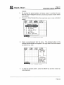
ILL.4-19 shows the patterns using Primary trigger signal. In case the
Secondary trigger has been selected , the voltage lines may be unstable.
Also the Spark Time will not be displayed .
Page 53
B HANATECH
6)
Page 54
DeN PRO USER'S MANUAL
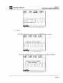
In Bar Graph mode, the spark time and peak voltage will be displayed
together if the Primary trigger has been selected . If the Secondary trigger has
been selected , only the peak voltage will be indicated . (ILL . 4-20-21) .
B.HOLD
~ . CYLN
1.SCND
2 .TlME UOLT
. . 6 .NEGATlUE
.
- 3 - 4 - 2
.
.;wllt.."t~
D
.....
.....
.....
3 .MOUE
PAGE39
......
'
'
1.7m
12kU
'
~
'
~
1 .7m
l1kU
1 .7m
12kU
.......
......
1.7m
12kU
2ms 1BkU RPM:1BBB BAT: 14.BU AMP: - 26 .4A
ILL.4 - 20. Secondary Bar Graph - Primary Tr i gger
9,HOLO
4 ,CV!.N
1,SeND
_II~:'¡
D-
2 ' T 111(: VOLT
{.,NEGATIUt
1.t1OUl3
PAGE39
3 - " - 2
~'
12kU
...-1'
111>\1
...
...,¡
12kU
lZkU
2ns
le~V
RPI1 :1S89 eA! : 14 ,SV AMP :-2& ,4A
ILL .4 - 21. Secondary Bar Graph - Secondary Trigger
D. Display Control Functions
Refer to the Primary Pattern part,
Page 54
B HANATECH
Page 55
DeN PRO USER'S MANUAL
4. Ignition - DLI / DIS Engines
'DLI' stands for Distributor-Less Ignition - An ignition system without a
distributor.
Since a DLI vehicle has an ignition coil for each ignition plug or one for every
two plugs, it requires different procedures for correct connections and data display.
A. Individual Ignition Type
1)
Menu Selection
a.
Select '1. O.L.I. Individual Ignition' type from the engine type selection
menu . DeN then displays the cable connection message.
IGNITION
•
3: DISTRIBUTOR 3
4. DISTRIBUTOR 4
5. DISTRIBUTOR 5
6. DISTRIBUTOR 6
7. PC INTERFACE
: MOVE
i t
ILL. 4 -22 .
Function
~.HOLD
~.CVUf
CYLINDER
CYLINDER
CYLINDER
CYLINDER
ENTER : SELECT
Initial Menu of Ign i tion Pattern
1 .PRHt
5 . DJSP
2 . TlHE UOLT
6.POSJHVE
3.tiOVI
PAGr:
DLI EfS(I) Pr imarv IG
Connect Cables
HtLP : He" 1:0 connect
ENTER : ConnE!ct clI1plete
e
2ms
sal' RPM:
MI:
O-BU AMP:
O-I1IA
ILL. 4 - 23 . Connect Cab l es message
Page 55
B HANATECH
Page 56
DeN PRO USER'S MANUAL
b. When the [ENTER] key is pressed, the message 'searching for signa!' will
appear briefly . The Primary Ignition Pattern will then be displayed (should
the secondary trigger has been selected, the secondary pattern will be
displayed).
..
B.HOLD 1 .PRIH ZTH1E lJOLT
.CYLN 5 .DlSP 6.POSITIUE
32'7\1 33 )(
~I.,'1"
,
2ns
3 .HOOE
PAGL24
PEAK DUILL
28lJ JUIH : Ul80
B~T:
13 .3U AliP: 10 .6~
I LL . 4 -24. DLI Primary Ignition
2)
Secondary Ignition Pattern
a.
To change to Secondary Pattern , select [1.PRIM] by pressing the [1] key
while displaying the Primary Pattern.
b.
Trigger Selection
For Secondary Ignition Pattern display, the trigger signal must be
selected.
•
Secondary Signal : Picks up the trigger signal from the Secondary
Pattern itself. Just attach the probe without needle(red) to one of
the high tension cables that extend to each spark plug, and the other
end to CH2 . No connection for CH1 .
•
Primary Signal : Picks up the trigger signal from the Primary Pattern .
Connect the probe with needle to the primary side negative line of
ignition coil , and the other end to CH1 port. And the probe without
needle(red) to a high tens ion cable and CH2.
Page 56
B HANATECH
page 57
DeN PRO USER'S MANUAL
::
IQnitiCll Coil
!~~!
1
It is easy and simple to use the secondary signal as trigger - just connect
the probe without needle to a high tension cord. That is all.
However, since the secondary signal is easily affected by engine RPM
and engine load, the resulting waveform may be incorrect and unstable.
Therefore, it is always recommended to use the Primary signal as a trigger.
Despite all the reasons for use of primary ignition signal, sometimes it is
necessary to use the secondary trigger signal when the primary lines cannot
be found. Sometimes the lines of some DLI cars are hidden under metal
shields and plates or may be too short for proper attachment of the probe.
Trigger Signal
Primary
Secondary
c.
Probe with needle
CH1 . Negative line
of primary ignition coil
NON E
Probe without needle
CH2. High tension
cable to ignition plug
CH2. High tension cable
to ignition plug
Waveform output
Primary and
Secondary (stable)
Secondary only
(unstable)
Press the [ENTER] key when the cable connection is completed.
The secondary patterns will then be displayed.
Page 57
B HANATECH
3)
Page 58
DeN PRO USER'S MANUAL
Secondary Ignition Waveform Output
a.
When all probe and cable connections have been correctly made, the
ignition waveform will be displayed as shown in ILL-4-25.
..
B.HOLD IIt-'1tJlll 2. TIME VOLT
4.CVLN 5.DISP 6.POSITIVE
A
',-,r
.
2ms
3 .MOVE
PAGE 4
PEAK SPRJ<
r
llkV l.Bm
1kV RPM:1BBB BAT: 13.41) AMP:-19 .7A
ILL . 4 - 25 . DLI Secondary Pattern
b.
4)
For individual ignition DLI engines, the patterns of each cylinder must be
viewed one by one. Connect the probe without needle to the other high
tension cable, and then repeat the previous procedure. The cylinder
number will always be marked 11.
Display Control Functions
a.
CYLN and DISP functions are not available with individual ignition DLI
engines .
Only one pattern per cylinder may be viewed at a time.
b.
AII other functions perform the same as previously explained .
the section on distributor type ignition vehicles .
Refer to
Page 58
B
Page 59
HANATECH
DeN PRO USER'S MANUAL
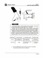
B. Synchronized Ignition Type - Double Ended Coil
1)
Trigger Selection and Probe Connection
a.
Double ended coil type DLI engines: Two spark plugs per ignition coil
b. These kind of cars can be divided into three types :
•
•
•
C.
Type A: One of the two high tension codes is exposed while the
other one is hidden inside metal shielding (ILL. 4-26).
Type B: Both of the high tension codes are exposed(ILL. 4-27), but
the primary side lines are not available.
Type C: No primary lines are available. One of the high tension
cables is hidden .
For Type A, you can use the primary trigger may be used for a stable
pattern display. Connect the probe with needle to the negative line of
the primary ignition coil , and the probe without needle to the exposed
high tension cable (ILL. 4-26).
Ptimary Ignition
Signal Li1e
+
ILL.4 - 26. DLI Double Ended Coil - Primary Tr i gger
Page 59
B HANATECH
Page 60
DeN PRO USER'S MANUAL
Red probe
without needle
+)Discharge
-)Discharge
ILL.4-27. DLI Double Ended Coil - Secondary Trigger
d. For Type B, you can select the secondary trigger itself as
shown in ILL.4-27. Connect the clamp to one of the negative high tension cables (CH3). Attach the probe without
needle to the other positive cable (CH2).
e. For Type C, a stable pattern display can not be obtained.
Just connect the probe without needle to the high tension
cable (CH2). One probe without needle will be used for both
voltage induction and secondary trigger pickup.
The pattern may be unstable.
Primary
CH1.Negative line of
prlmary Ignltion coil
Secondary
None
CH2. High tenslon
cable to Ignltlon plug
Primary and
Secondary (stable)
CH2. High tension
Secondary only
Cable to Ignition plug
(Unstable)
Page 60
B HANATECH
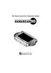
2)
Page 61
DeN PRO USER'S MANUAL
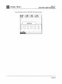
Waveform Display
When all probe and cable connection have been properly made, an ignition
waveform will be displayed as shown in ILL.4-28 .
. HOLD 1 .PRIH ,.
I
3.HOVE
.CYLN S.DISP 6.POSITIVE
PAGE 7
IDI :
: PEAK SPRK
....... .•. 335V .:13 'i:' .
. ···· 32f!V33x ..
RPH:2BBB DAT: 12.7V AHP: - - - A
3)
Secondary Pattern
a.
If the Secondary Trigger is selected , DeN PRO will display the
When you
Secondary Pattern without displaying the Primary Pattern .
use the Primary Trigger, DCN PRO displays the Primary Trigger first. It is
necessary to choose [1 .PRIM] to change the mode to Secondary Pattern.
b.
Trigger Selection
When you choose the secondary pattern from the aboye menu , trigger
selection menu follows . Choose the trigger according to your cable connection .
. HOLD 1 .PRIH
. TIHE VOL
.CYLN S.DISP 6 .POSITIVE
3.HOVE
PAGE 7
PEAK SPRK
Select Trigger
1 . Pr i mary (CHU
2. SecondaryeCH2)
... : 33:11,133· x .
lms
2BV RPH :2BBB DAT : 12.7V AHP: --- A
ILL .4 - 29. Trigger Selecti o n
Page 61
B HANATECH
Page 62
DeN PRO USER'S MANUAL
B.HOLD __"1.", I
4.CYLN 5 .DISP
D- 2
'
~
..-
.
r
2ms
2.TIHE VOLT
6.POSITIVE
3.HOVE
PAGE 4
PEAK SPRJ<
J.
r
llkV 1.8m
lA
• ¡'
4kV 1.3m
1kV RPH:1BBB BAT : 13.4V AHP:-19 .7A
ILL . 4 - 30. Secondary Pattern - DLI Double Ended Co il
As shown in the illustration, DCN PRO displays two waveforms . This is
because an ignition Coil of this type discharges both positive and negative
electricity simultaneously to two spark plugs.
For 4-cylinder engines, there are two ignition coils and each coil is connected
to two spark plugs. When one of the coils discharges positive electricity for
example to cylinder #1, it also discharges negative electricity to cylinder #4
simultaneously. When the other coil discharges positive electricity to cylinder #3,
it also discharges negative electricity to cylinder #2 simultaneously.
Therefore, there will be positive discharges in cylinder #1 and #4, and negative
discharges in cylinder #3 and #2 at the same time. Will this cause cylinder #1
and #4 to fire together? No. When one cylinder is in combustion stroke, the
other will be either in the exhaust, intake or compression stroke. Since the
mixture in the other cylinders is not dense enough to properly combust, it burns
but does not fully combust.
From the two cylinders that ignite together, the waveform of the valid electricity
discharge that creates combustion is called 'True Waveform', and the other that
ignites but does not fully combust is called 'Waste Waveform'.
The density of mixtures in the cylinders that are in the strokes other than
combustion stroke are below combustible level. The higher the resistance level,
the higher the voltage is required to bridge the ignition gap . This means that the
peak voltage of the TRUE waveform is higher than that of the WASTE waveform.
Between the two waveforms , TRUE waveform can be distinguished from the
WASTE form in this manner. In ILL. 43, the second waveform is TRUE .
Page 62
B HANATECH
4)
Page 63
DeN PRO USER'S MANUAL
Display Control Functions
a.
NEGATIVE / POSITIVE
Selects the discharge polarity of spark ignition
•
•
b.
O When the selected polarity differs from vehicle's actual discharge
polarity: the waveform may be displayed upside down or the waveform
may not be displayed at all
The polarity switch es between Positive and Negative when the [5] key is
pressed
AII other functions do the same as previously explained.
distributor vehicle parto
Refer to the
5. Print Output
Refer to Chapter 3. Oscilloscope, Part 4. Print Output.
Page 63
B
Page 64
HANATECH
DeN PRO USER'S MANUAL
HAN A TECH CO., LTD.
Automotive Diagnostic Equipment Specialist
(E
Global Standard
DCN PRO CE Marked
Head Quarter
Hana Bldg ., 80-1 Songjung-dong, Gumi-shi
Kyungbuk-do, 730-090 Korea
Phone: +82-54-454-9009
Fax: +82-54-454-8554
Website: http://www.hanatech .net
"" Copyright 2002 by Hana Tech Co., Ud.
Publíshed in Korea
Page 64