1
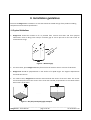
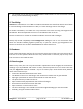
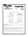
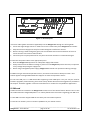
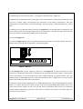
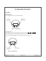
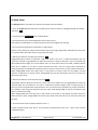
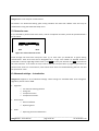
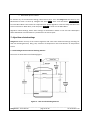
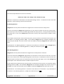
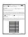
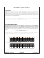
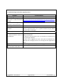
 GaugerGSM User Manual You Can Measure the Solid Benefits… Notices and safety guidelines This manual is delivered subject to the following conditions and restrictions: • The manual contains proprietary information belonging to Solid Applied Technologies Ltd. The information is published solely for the purpose of assisting authorized users of the GaugerGSM. • No part of this manual may be used for any other purpose, or disclosed to any person or firm, or reproduced by any means, without the prior written permission of Solid Applied Technologies Ltd. • The text and graphics in this manual are for the purpose of illustration and reference only. • Information included in this manual is subject to change without notice. Information in the manual may contain inaccuracies. We always welcome suggestions and recommendations from the users of our manuals. • All company, brand products and service names that may appear in this manual are trademarks or registered trademarks of their respective holders. • Solid Applied Technologies shall not be liable for any loss or damage caused by the use of this manual or of products described in the manual. Solid Applied Technologies sole warranty is that products sold by the company shall be free of defects in material and in workmanship for a period of 12 months. • GaugerGSM must be installed, connected and operated in accordance with the instructions of this manual and with the GaugerGSM certifications. • Do not open or disassemble GaugerGSM except as required for electrical connections. • Any type of modifications and repairs are permissible only upon the manufacturer or re‐seller written approval and by pre‐qualified personal. Never reuse defective parts. Date Revision Software version Part number Jan 2010 1.04 GaugerGSM 1.88 GaugerGSM75 ______________________________________________________________________________ GaugerGSM – User Manual page 2 of 39 Jan 2010 Rev 1.04 Table of Contents NOTICES AND SAFETY GUIDELINES......................................................................................................................... 2 TABLE OF CONTENTS .............................................................................................................................................. 3 LIST OF FIGURES ..................................................................................................................................................... 5 I. INTRODUCTION .................................................................................................................................................. 6 1. DESCRIPTION ............................................................................................................................................................. 6 2. GAUGERGSM PARTS ................................................................................................................................................... 7 3. DIMENSIONS ............................................................................................................................................................. 8 4. SPECIFICATIONS .......................................................................................................................................................... 9 II. INSTALLATION GUIDELINES .............................................................................................................................. 11 1. PHYSICAL GUIDELINES ............................................................................................................................................... 11 2. TANK FITTING .......................................................................................................................................................... 12 3. DEAD ZONE ............................................................................................................................................................. 12 4. EXTENSION PIPE ....................................................................................................................................................... 12 5. SOFTWARE SETUP ..................................................................................................................................................... 13 5.1 Using NBD ..................................................................................................................................................... 13 5.2 Using false echo scan .................................................................................................................................... 14 5.3 Verify settings ............................................................................................................................................... 14 6. CELLULAR ANTENNA .................................................................................................................................................. 14 7. EXTERNAL AND INTERNAL TEMPERATURE SENSORS .......................................................................................................... 14 8. ELECTRICAL CONNECTIONS .......................................................................................................................................... 14 9. SIM CARD ............................................................................................................................................................... 15 III. OPERATING INSTRUCTIONS ............................................................................................................................ 17 1. KEYPAD .................................................................................................................................................................. 17 1.1 Navigation keys ............................................................................................................................................. 17 1.2 Execution keys ............................................................................................................................................... 17 2. NAVIGATION THROUGH MENUS ................................................................................................................................... 18 2.1 Sub‐Menu style ............................................................................................................................................. 18 2.2 Numeric menu style ...................................................................................................................................... 18 2.3 Menu and sub‐menu organization ................................................................................................................ 20 3. MEASUREMENT SCREEN ............................................................................................................................................. 21 3.1 Status reports ................................................................................................................................................ 21 3.2 Contrast ......................................................................................................................................................... 21 3.3 Main menu .................................................................................................................................................... 22 3.4 Temperature readings ................................................................................................................................... 22 3.5 Ultrasonic echo conditions ............................................................................................................................ 22 3.6 Product identification details ........................................................................................................................ 22 4. QUICK SETUP ........................................................................................................................................................... 23 5. FALSE ECHO SCAN ..................................................................................................................................................... 24 6. ADVANCED SETTINGS – INTRODUCTION ......................................................................................................................... 24 ______________________________________________________________________________ GaugerGSM – User Manual page 3 of 39 Jan 2010 Rev 1.04 7. ALGORITHM RELATED SETTINGS ................................................................................................................................... 25 7.1 Far blocking distance and near blocking distance ........................................................................................ 25 7.2 Filling Rate .................................................................................................................................................... 27 7.3 Temperature units ......................................................................................................................................... 27 7.4 Temperature sensors .................................................................................................................................... 27 8. DEVICE STATE .......................................................................................................................................................... 27 8.1 Reset to manufacturer defaults .................................................................................................................... 28 8.2 Operating hours ............................................................................................................................................ 28 9. DEFAULT VALUES ...................................................................................................................................................... 28 IV. CELLULAR COMMUNICATION ......................................................................................................................... 29 1. DESCRIPTION ........................................................................................................................................................... 29 2. DESTINATION PHONE NUMBER .................................................................................................................................... 29 3. GSM REPORT INTERVAL ............................................................................................................................................. 30 4. FULL AND EMPTY ALERTS ............................................................................................................................................ 30 5. THEFT ALERTS .......................................................................................................................................................... 30 6. REFILL ALERTS .......................................................................................................................................................... 30 7. GSM DISPLAY STATUS REPORTS ................................................................................................................................... 31 8. SMS FORMAT .......................................................................................................................................................... 31 V. FIRMWARE UPGRADE ...................................................................................................................................... 32 VI. SERIAL DATA OUTPUT ..................................................................................................................................... 34 1. PURPOSE AND INSTALLATION ...................................................................................................................................... 34 2. RECORD FORMAT ...................................................................................................................................................... 34 VII. TROUBLESHOOTING ...................................................................................................................................... 36 NOTES .................................................................................................................................................................. 37 INDEX .................................................................................................................................................................. 38 ______________________________________________________________________________ GaugerGSM – User Manual page 4 of 39 Jan 2010 Rev 1.04 List of Figures Figure 1 ‐ GaugerGSM parts .......................................................................................................................... 7 Figure 2 ‐ GaugerGSM dimensions................................................................................................................ 8 Figure 3 – Minimum gap ............................................................................................................................. 11 Figure 4 ‐ Silo (left) and liquid (right) examples .......................................................................................... 11 Figure 5 – Possible extension pipe settings ................................................................................................ 13 Figure 6 – Possible extension pipe fittings .................................................................................................. 13 Figure 7 ‐ Electrical ports ............................................................................................................................ 15 Figure 8 ‐ SIM Card ...................................................................................................................................... 16 Figure 9 ‐ Navigation keys ........................................................................................................................... 17 Figure 10 ‐ Execution keys .......................................................................................................................... 17 Figure 11 ‐ Sub menu screens ..................................................................................................................... 18 Figure 12 ‐ Numeric menu .......................................................................................................................... 19 Figure 13 ‐ Menu and submenu organization ............................................................................................. 20 Figure 14 ‐ Measurement screen ................................................................................................................ 21 Figure 15 ‐ Temperature readings .............................................................................................................. 22 Figure 16 ‐ False echo scan screen .............................................................................................................. 24 Figure 17 ‐ Near and far blocking distance ................................................................................................. 25 ______________________________________________________________________________ GaugerGSM – User Manual page 5 of 39 Jan 2010 Rev 1.04 I. Introduction 1. Description GaugerGSM is an ultrasonic level sensor with embedded cellular communication capabilities, all in one enclosure. GaugerGSM measures distance or level from targets. Targets may be liquid or solids. Measurement is continuous and does not require contact with the target. The system can accurately measure steady or agitated target surfaces. The system can also rapidly track filling and emptying of vessels. GaugerGSM transmits measurement information to a predefined destination – whether cellular phone or cellular PC modem. The information is transmitted via SMS. Reporting interval is user‐programmable. The system also identifies and sends an alert in boundary events such as full and empty situations. The system can be programmed to identify and alert for rapid changes of level indicating theft or leakage. GaugerGSM is equipped with a large graphic display and keypad allowing a simple wizard‐driven setup of the system. The system measurement range spans 15 cm to 8 meters. This user manual is intended for users and operators of GaugerGSM. The manual covers system description, installation, operation and troubleshooting of GaugerGSM. ______________________________________________________________________________ GaugerGSM – User Manual page 6 of 39 Jan 2010 Rev 1.04 2. GaugerGSM parts Figure 1 ‐ GaugerGSM parts ______________________________________________________________________________ GaugerGSM – User Manual page 7 of 39 Jan 2010 Rev 1.04 3. Dimensions All figures in mm. Figure 2 ‐ GaugerGSM dimensions ______________________________________________________________________________ GaugerGSM – User Manual page 8 of 39 Jan 2010 Rev 1.04 4. Specifications Measuring range Maximum range for liquids ‐ Maximum range for Solids ‐ Accuracy – precision – resolution ‐tracking Accuracy 15cm<Range<60cm ‐ 60cm<Range<5m ‐ 5m<Range<8m ‐ Precision (repeatability) ‐ Display resolution ‐ SMS resolution ‐ ‐ Process tracking rate Electrical specifications Power supply ‐ Current consumption at 24VDC Continuous ‐ During SMS transmission ‐ At switch on ‐ Data interface ‐ Display ‐ Ultrasonic frequency ‐ Cellular modem specifications Band ‐ Output power ‐ ‐ SMS ‐ GPRS ‐ Reports Displayed ‐ 8 meter 6 meter 1.5mm 0.3% of measured range 0.2% of maximum range 0.2% of measured range 1 mm 1 mm 10 meter per minute maximum 8 to 33 VDC (for firmware upgrade only – USB power) Less than 10mA Less than 40mA Spikes less than 60mA Serial COM over USB at 115,200bps 64X128 Graphic LCD, viewing size 50X25mm2 75 KHz Quad band 850/900/1800/1900 MHz Class 4 (33dBm) for EGSM850/EGSM900 Class 1 (30dBm) for GSM1800/GSM1900 Point‐to‐point MO and MT Multi‐slot class 10 Coding schemes 1‐4 Level and percentage level Distance and percentage distance Temperature (internal and external) Echo strength ______________________________________________________________________________ GaugerGSM – User Manual page 9 of 39 Jan 2010 Rev 1.04 Global operating hours Resettable operating hours Ultrasonic status reports Cellular status reports Level, Distance, Temperature, Status Sent by SMS Temperature characteristics Operational temperature range ‐ ‐ Temperature sensors Temperature compensation Temperature display Mechanical specifications Enclosure material Sensor material Sealing rating Mounting threads Cable entries Weight Certifications ‐ ‐ ‐ ‐20°C to +70°C ‐30°C to +70°C for GaugerGSM without display Two: internal and external Built‐in based on internal sensor, external sensor or average of the two Internal and external temperature Instantaneous and recorded high/low ‐ ‐ ‐ ‐ Plastic PC/ABS+UV PVDF IP65/IP67 IP68 ‐ 96 hours at 1.8 meter depth in water ‐ ‐ ‐ 1.5” BSP or 1.5” NPT Conduit ½”NPT 960 gram ‐ CE: EMC and Safety FCC Part 15 ______________________________________________________________________________ GaugerGSM – User Manual page 10 of 39 Jan 2010 Rev 1.04 II. Installation guidelines Ensure that GaugerGSM is installed in an area that meets the stated ratings of the product including temperature and technical specifications 1. Physical Guidelines •
GaugerGSM should be located as far as possible from vertical tank walls and from physical obstructions such as filling inlets. Keep a minimum gap of: 25 cm plus 10 cm for each meter of measurement range. Figure 3 – Minimum gap •
•
•
For best results, place GaugerGSM away from sources of acoustic noise or sources of vibrations. GaugerGSM should be perpendicular to the surface of a liquid target. The angular displacement should be less than 5°. For solids in silos, GaugerGSM should be aimed towards the center of the silo’s base. The sensor should be displaced from the center of the tank and oriented perpendicular to the solids surface when tank is at full state. Figure 4 ‐ Silo (left) and liquid (right) examples ______________________________________________________________________________ GaugerGSM – User Manual page 11 of 39 Jan 2010 Rev 1.04 •
The sunshade may be separated from GaugerGSM in shaded locations or when the sunshade cannot be easily reached when viewing the display. 2. Tank fitting GaugerGSM is equipped with a 1.5”BSP or 1.5”NPT thread allowing two tank fitting options: direct fitting in a threaded flange or fastened with a 1.5” BSP / 1.5” NPT nut through a thread‐free flange. For outdoor installations, use a stable arm. Firmly attach the sensor to the arm using a through‐hole and threaded nut. Alternatively, attach the sensor to a threaded hole built‐in the arm. Call the manufacturer or re‐seller for available installation accessories and arm designs. Always verify thread compatibility between GaugerGSM and flange or nut. Do not use excessive force when using threads. Preferably, tighten by hand only. If you do use a wrench, grip GaugerGSM at the wrench grip surfaces only (see figure GaugerGSM parts) and exert light force. 3. Dead zone A gap must be kept between the face of sensor and the topmost level of the target. This gap must be at least the size of the specified “dead zone”. You may need to install an extension pipe if the top most level is too near to the roof of the tank. 4. Extension pipe While in many cases, the sensor may be immersed in liquid and will not be damaged, the measurement readings may be unpredictable and random. In tanks, where the topmost level is too close to the tank roof, the GaugerGSM should be installed on top of an extension pipe. Closely follow these guidelines when using an extension pipe: • Internal pipe diameter should be at least 3” wide • The diameter of the hole on the flange or tank should not be smaller than the pipe diameter • Pipe length (measured from sensor face) should be no longer than 50 cm • The pipe should not protrude into the tank • Pipe should be exactly perpendicular to the surface of the target • Sensor must be located at the center of the pipe • Pipe should have a smooth interior surface • The hole in the flange or tank should have a smooth edge and welding spots must be avoided • Preferably, the pipe should be made of plastic ______________________________________________________________________________ GaugerGSM – User Manual page 12 of 39 Jan 2010 Rev 1.04 Figure 5 – Possible extension pipe settings Figure 6 – Possible extension pipe fittings 5. Software Setup Software setup is fully described in the chapter Operation instructions. This section highlights some of the issues to be aware of during installation. 5.1 Using NBD If distance between the sensor face and the topmost level of the target is larger than the specified “dead zone” by at least 5cm, you should consider defining an NBD. The NBD should be defined as 2‐3 cm shorter than the distance to the topmost level. This will ensure that GaugerGSM will not measure obstructions slightly above the topmost level and report them as full level. Similarly, when an extension pipe is used, and the length of the extension pipe is larger than the “dead zone”, you should define NBD which is larger by 2‐3 cm than the length of the extension pipe. This will ______________________________________________________________________________ GaugerGSM – User Manual page 13 of 39 Jan 2010 Rev 1.04 ensure that you will not pick up echoes arising from the bottom end of the pipe and report them as full level. 5.2 Using false echo scan Perform a false echo scan when obstructions are nearby the target or sensor. Preferably, false echo scan should be preformed when the tank is empty. 5.3 Verify settings Always verify then re‐verify that your basic settings are correct including distance to empty level, distance to full level, level or distance choice. Most wrong readings originate from incorrect setup. 6. Cellular antenna An antenna must be connected to GaugerGSM, either internal or external. The antenna must provide clear communications with the cellular network. If your GaugerGSM supports an external cellular antenna, locate the antenna at a high altitude position and check that SMS are properly sent. This can be tested by modifying the reporting interval to a low value such as 30 seconds, inserting your own private cellular phone number as the destination number and checking the regularities of the SMS that are received by your phone. 7. External and internal temperature sensors If your GaugerGSM supports an external temperature sensor, place the sensor at a location that best represents temperature of the air between the sensor face and the target. Connect the sensor internally as described in the electrical connection section. External temperature sensors may be ordered from the manufacturer or reseller or may be purchased independently. Use Thermistor NTC 10K Ohm 5% (minimum) P/N 2381‐640‐63103 by Vishay BC Components or equivalent. When using the internal temperature sensor, avoid situations where the GaugerGSM is exposed to different thermal conditions than its environment (for example avoid direct heating). 8. Electrical connections 8.1 Turn off GaugerGSM. 8.2 Turn the GaugerGSM top cap anti‐clockwise and expose the electrical connections board. Review the connections as described in the following figure. ______________________________________________________________________________ GaugerGSM – User Manual page 14 of 39 Jan 2010 Rev 1.04 Figure 7 ‐ Electrical ports 8.2 Insert cables (power and data as applicable) into the GaugerGSM through one of the glands. • Ensure that high voltage sources or cables are at least 1 meter away from GaugerGSM and cables. • Keep the electrical supply lines away from electromagnetic interference sources. • When inserting a cable through the gland, use round cables with minimum diameter of 6 mm to ensure that the unit remains sealed to IP67. • Connector ports may be pulled out for easy wire connection and then re‐inserted back again. 8.3 Connect the power cables to the appropriate ports. • Note that GaugerGSM operates from a DC power supply of 8‐33 VDC. • Always make sure that sufficient voltage is present on the GaugerGSM power terminals, irrespective of any voltage drop along the supply lines • When using rechargeable power supply, GaugerGSM should be non operational during recharge 8.4 When using an external temperature sensor, connect the thermistor to data pins 6 and 7. This section applies to GaugerGSM models that support an external temperature sensor. 8.5 The mini‐USB port is a USB device‐side supporting virtual COM ports. The port may be used for firmware upgrades, field monitoring and remote setup. Details about firmware upgrade are provided in the chapter: Firmware upgrade. Contact the manufacturer or reseller for compatible PC applications. 9. SIM card A SIM card must be installed in the GaugerGSM to allow use of the cellular feature. Never insert or take out a SIM card when GaugerGSM power is on. Closely follow these instructions regarding your SIM card: 9.1 The SIM Card must support SMS services with your local cellular operator. 9.2 You do not need any voice or browser capabilities in your cellular service. ______________________________________________________________________________ GaugerGSM – User Manual page 15 of 39 Jan 2010 Rev 1.04 9.3 Depending on your cellular operator – you might be required to use a USIM card. 9.4 Deactivate the SIM PIN code if the PIN code is active. Deactivation is preformed by inserting the SIM card into a cellular phone and following the instructions of the phone manufacturer. PIN code configuration is usually found in your phone Settings – Security Settings – PIN Code Request or a similar path. 9.5 Always test your SIM card before inserting into GaugerGSM. Test the SIM card by inserting the card into a cellular phone and sending an SMS. Verify that no PIN code is required, that the proper operator serves the cellular link and that the SMS reaches its destination. 9.6 Turn off GaugerGSM. 9.7 Turn the GaugerGSM top cap anti‐clockwise and expose the electrical connections board. Insert the SIM card into the proper slot as described in the following figure. Figure 8 ‐ SIM Card 9.7 Aim GaugerGSM to proper target (e.g. floor), turn on GaugerGSM and closely observe the lower status line on the display (status lines are explained in the operating instructions chapter ‐ measurement screen sub‐chapter). You should observe the report “GSM Initializing” for 30‐60 seconds. Then you should observe a “GSM Registration OK” status and immediately after ‐ “GSM Active”. This set of status reports would indicate proper SIM card operation. 9.8 If status reports present “GSM SIM Fail” or “GSM Registration Fail” (but the SIM did operate properly earlier in a cellular phone!) the cellular operator may have rejected GaugerGSM modem. If you can, check with technical support of the local operator about compatibility with Siemens (or Centurion) modem MC55i. Alternatively, purchase a SIM card from another local operator and follow again the instructions of this section. ______________________________________________________________________________ GaugerGSM – User Manual page 16 of 39 Jan 2010 Rev 1.04 III. Operating instructions 1. Keypad 1.1 Navigation keys Use the navigation keys to scroll through the display. Left‐Up navigation key Right‐Down navigation key Figure 9 ‐ Navigation keys 1.2 Execution keys Use the execution keys to change a digit or to execute a command (Back, Next or Sub‐menu): To change a digit: navigate to the digit and press the Plus (+) key or the Minus (‐) key. To execute a command: navigate to the command and press the Enter (+) key. Increase digit or Enter Decrease digit
Figure 10 ‐ Execution keys ______________________________________________________________________________ GaugerGSM – User Manual page 17 of 39 Jan 2010 Rev 1.04 2. Navigation through menus GaugerGSM supports two menu styles which are used throughout the setup operations and are described below. False echo scan employs another menu style and is described at the relevant section. 2.1 Sub‐Menu style The Sub‐Menu style presents a list of vertical choices. An arrow may appear on the right hand side of the screen if additional items can be reached when scrolling down. The scrolling is cyclic meaning that when you reach the last (first) item, the next step will lead you to the first (last) item. Scroll up or down, using the navigation keys, to your selected choice and press Enter (+). This action will lead you to the next Sub‐
Menu. The last item in the list of choices is **back**. Select **back** to return to the previous menu. The previous menu will be displayed such that your last selection will appear first on the menu. For example: DISTANCE UNIT Select meter feet **back** VALUE TO DISPLAY Select Distance Level %Distance Figure 11 ‐ Sub menu screens 2.2 Numeric menu style The Numeric menu style presents you with a multi‐digit number which may be modified. Navigate to each digit and modify the digit as required by using the Plus (+) or Minus (‐) keys. ______________________________________________________________________________ GaugerGSM – User Manual page 18 of 39 Jan 2010 Rev 1.04 When you are done with all digits, select Next to store the modified parameter. Select Back to ignore the changes and return to the previous sub‐menu. Modifications will become permanent (survive a reset) when you navigate back to the measurement screen. For example: Back EMPTY LEVEL Enter distance from sensor face to empty level X1.X2X3X4 meter Next Figure 12 ‐ Numeric menu By repeatedly pressing the Right‐Down navigation key, you will follow this route: X1 Æ X2 Æ X3 Æ X4 Æ Next Æ Back Æ X1Æ X2 Æ… By repeatedly pressing the Left‐Up navigation key, you will follow the opposite route. After pressing Next, Gauger will check the validity of your numerical entry. If your entry is outside the acceptable boundaries, an ILLEGAL VALUE screen will be presented. You need to press any key to return to the previous screen. A default value will replace your wrong entry. If so needed, modify the numerical entry and press Next again. ______________________________________________________________________________ GaugerGSM – User Manual page 19 of 39 Jan 2010 Rev 1.04 2.3 Menu and sub‐menu organization GaugerGSM menus and submenus are organized in a tree‐like format. The organization is described in the following figure. Figure 13 ‐ Menu and submenu organization ______________________________________________________________________________ GaugerGSM – User Manual page 20 of 39 Jan 2010 Rev 1.04 3. Measurement screen Level 1.234 meter EMPTY LEVEL GSM SMS SENT Measurement report Status reports ±¤ setup T° dB ID Toolbar
Contrast Main menu
Temperature readings
Ultrasonic echo conditions
Product identification details
Figure 14 ‐ Measurement screen
The top line presents the current measurement information. 3.1 Status reports Status reports appear beneath the measurement result. On the first line, reports related to ultrasonic metering issues are presented. On the next line, cellular communication related reports are presented. Ultrasonic reports include messages such as: FULL LEVEL, EMPTY LEVEL, ECHO SEARCH, THEFT, START FILL, END FILL and others. Cellular related reports include messages such as SMS SENT, SMS ACTIVE or REGISTRATION FAILED. The bottom line presents a toolbar with a variety of choices. Navigate through the toolbar and select the required action or report. GaugerGSM halts any operations (measurement and GSM transmissions) during navigation. Gauger will automatically resume operations 30 seconds after last key has been pressed. 3.2 Contrast Press the Plus (+) or Minus (‐) keys to change visual contrast of the display. ______________________________________________________________________________ GaugerGSM – User Manual page 21 of 39 Jan 2010 Rev 1.04 3.3 Main menu Navigate to Setup and press Enter (+) to configure GaugerGSM. See chapter: Operating instructions. 3.4 Temperature readings Navigate to the T° symbol on the toolbar and press Enter (+). The following table will be displayed: Sens: Cur High Low Int 29.5 31.0 26 Ext 29.4 32 23.3 Reset Done Figure 15 ‐ Temperature readings The second line displays temperature measured by the internal temperature sensor. The third line displays temperature measured by the external temperature sensor. The column “Cur” displays the current temperature while “High” and “Low” columns display the highest and lowest temperature ever recorded by the temperature sensors since the last reset was performed. Press Reset to reset the recorded high and low temperature or press Done to return to the measurement screen. 3.5 Ultrasonic echo conditions Navigate to the dB symbol and press Enter (+). You will be presented with the measured echo amplitude and the maximum amplitude available. The amplitudes are presented in dB relative to a system threshold amplitude. Echo amplitude should be above threshold amplitude for reliable measurement. Echo strength between 3dB and 8db (maximum) is reliable. Echo amplitude refers to the echo measured just prior to navigating through the toolbar. Press Done to return to the measurement screen. 3.6 Product identification details From the measurement screen, navigate to the ID symbol on the toolbar and press Enter (+). Product information will be displayed: Serial Number and Part Number. Press Back to return to the measurement screen or navigate to one of the options: Software information (SW), Hardware information (HW) or Manufacturing Date information (Date). SW screen will display firmware versions of the embedded application and of the embedded Boot‐
Loader. Press Back to return to the previous menu. HW screen will display product information regarding sensor type and model type. Press Back to return to the previous menu. Date screen will present the date of manufacturing. Press Back to return to the previous menu. ______________________________________________________________________________ GaugerGSM – User Manual page 22 of 39 Jan 2010 Rev 1.04 4. Quick Setup Set GaugerGSM for operation by a quick 8‐step wizard‐driven procedure. 1. Turn on GaugerGSM and wait for the measurement screen to show up. Navigate through the toolbar and select setup. 2. Scroll and select Basic Setup from the Main Menu. 3. Scroll and select your preferred distance units (meter, feet…). This selection implies Metric or Imperial (US) unit system throughout the settings. 4. Scroll and select application (Low power or High power). Always use low power for stable measurements unless your target appreciably attenuates the echo such as: powder solids, liquid with foam or long extension pipes. 5. Determine distance to empty level and press Done. GaugerGSM always allows a maximum range of 8 meters. The user is cautioned however that the maximum practical range depends on target characteristics. Range of 8 meters may be achieved with quiet liquid surface targets. As a rule of thumb, user no more than 6 meters for solids, turbulent liquids, when the air medium is not clear or when interferences exists. You may verify proper operation by checking whether the equipment frequently enters a state of “echo search” at your maximum distance. When GaugerGSM enters the empty level, it will present an empty status on the display and will transmit an SMS with an empty report. GaugerGSM will exit this state when level rises at least 2cm above the empty level. 6. Determine distance to the full level and press Done. The default value for distance to full level is 15cm. This is the “dead zone” of GaugerGSM and cannot be reduced under any circumstances. The user is cautioned to prevent targets from crossing this limit as this may result in unpredictable measurements. You can overcome this limitation by proper installation. For example, if the target can approach the tank roof, install GaugerGSM on top of an extension pipe which is at least 15cm long. When GaugerGSM enters the full level, it will present a full status on the display and will transmit an SMS with a full report. GaugerGSM will exit this state when level decreases by at least 2cm below the full level. 7. Scroll and select value to display (distance, level…). 8. Skip or perform false echo search. If you choose to perform false echo scan – refer to the relevant subchapter below. ______________________________________________________________________________ GaugerGSM – User Manual page 23 of 39 Jan 2010 Rev 1.04 GaugerGSM is now ready for measurements. Parameters not determined during quick setup procedure will take their default value and may be modified later using the Advanced Setup menu. 5. False echo scan If you selected to perform false echo search, wait for completion and then you will be presented with a list of echoes. False Echo Select 1 1 0.17 √ 2 New 0.25 1408 1207 Save Next Figure 16 ‐ False echo scan screen Scroll through the listed echo and press Enter (+) on each echo you would like to ignore during measurement. Each such echo will be designated by a √ sign. The number of selected echoes is presented on the top‐right edge of the screen. Press Save to store your selection and Next to proceed to the next sub‐menu. To un‐select an echo, scroll to that echo and press Enter (+) again. If you choose to perform false echo scan a second time, new echoes which were not identified during the first scan will be reported as “new”. 6. Advanced settings – introduction GaugerGSM supports a set of advanced settings. These settings are classified under three categories: Algorithm, Device state or GSM. • Algorithm 9 Far and near blocking distance 9 Filling rate 9 Temperature units 9 Temperature sensors • Device State 9 Reset to defaults 9 Operating hours • GSM 9 Reporting interval and deviation ______________________________________________________________________________ GaugerGSM – User Manual page 24 of 39 Jan 2010 Rev 1.04 9 Destination phone number To execute any of the advanced settings, follow these steps: Turn ON GaugerGSM and wait for the Measurement screen to show up. Navigate and select Setup. Then scroll and select Advanced Setup from the Main Menu. Now select the required action (GSM, Algorithm or Device state) and follow the screen instructions. When done, scroll and press **back** to return to the Main Menu. Algorithm related settings, device state settings are described in details in the next two subchapters while GSM cellular communications is presented in the next chapter. 7. Algorithm related settings GaugerGSM allows tune up of the internal algorithm and some other advanced settings including: far and near blocking distance, filling rate, selection of temperature units and selection of temperature sensor. 7.1 Far blocking distance and near blocking distance The terms are illustrated in the following figure. Figure 17 ‐ Near and far blocking distance ______________________________________________________________________________ GaugerGSM – User Manual page 25 of 39 Jan 2010 Rev 1.04 The relationships between the terms are as follows: Dead Zone < NBD < Full < Empty < FBD < Maximum range Follow the instructions as described in the advanced settings section – introduction section and select Algorithm. The far blocking screen will be presented. Far blocking distance GaugerGSM normally measures distance to targets which are closer than the “Empty level”. In some circumstances, GaugerGSM might detect an echo which is further out than the “Empty level”. This echo may be the result of the actual target below the empty level or a strong interference below the empty level. In such cases, GaugerGSM would report “Empty” and would transmit an SMS to report the event. If you expect echoes further out than the empty level, and you prefer to avoid these event reports, you can define a Far Blocking Distance (FBD). Once defined, GaugerGSM will completely disregard any echoes beyond the FBD. If no other echoes closer than FBD are detected, GaugerGSM will report lost of echo. The default for “Far Blocking Distance” is identical to the distance to maximum range of GaugerGSM. If you would like to reduce “Far Blocking Distance”, modify the number then press Next. Near blocking distance GaugerGSM normally measures distance to targets which are beyond the “Full level”. In some circumstances, GaugerGSM might detect an echo which is closer than the “Full level”. This echo may be the result of the actual target being above the full level or interference above the full level. Extension pipes normally cause such interferences from the lower pipe edge. In such cases, GaugerGSM would report “Full” and would transmit an SMS to report the event. If you expect echoes above full level, and you prefer to avoid these event reports, you can define a Near Blocking Distance (NBD). Once defined, GaugerGSM will completely disregard any echoes closer than the NBD. If no other echoes further than the NBD are detected, GaugerGSM will report lost of echo. The default for “near blocking distance” is identical to the distance to “Dead Zone”. If you would like to increase the “near blocking distance”, modify the number then press Next. ______________________________________________________________________________ GaugerGSM – User Manual page 26 of 39 Jan 2010 Rev 1.04 7.2 Filling Rate Follow the instructions as described in the advanced settings – introduction section and select Algorithm. Scroll and select Next in the far blocking distance screen and then Next in the near blocking distance screen. The filling rate options will be presented to you. You should increase the filling rate figure if your target fills up or drains down rapidly. Always use the lowest possible filling rate in order to preserve accuracy of the measurement. Scroll through the display and select a filling rate. Modify then press Next. Note that nearby full (empty) level, GaugerGSM tracking rate is somewhat reduced to avoid erratic entry into full (empty) level. Such erratic entry may cause abundant SMS messages reporting the recurring event. 7.3 Temperature units Follow the instructions as described in the advanced settings – introduction section and select Algorithm. Scroll and select Next in the far blocking distance screen and then again in the near blocking distance screen. Press the Entre (+) key in the filling rate screen. You will be presented with the temperature unit screen. Select either Celsius or Fahrenheit. 7.4 Temperature sensors Follow the instructions as described in the advanced settings – introduction section and select Algorithm. Scroll and select Next in the far blocking distance screen and then again in the near blocking distance screen. Press the Enter (+) key in the filling rate screen. Press Enter (+) in the temperature unit screen. You will be presented with the temperature sensor screen. GaugerGSM implements automatic compensation of deviations due to temperature variations in the air temperature of the ultrasonic media. The temperature is sensed by a temperature sensor which is embedded within the acoustic sensor. In installations where temperature varies very rapidly in time and location, it may be preferable to install an external temperature sensor which will follow more closely the varying temperature. Select Internal for the embedded sensor, select Externally‐connected if you intend to use an external sensor or choose to average both readings. See the chapter: installation guidelines for details about installation of the external temperature sensor. Press Next to return to the advanced menu. 8. Device state Device state options include reset to manufacturer defaults and review/reset of operating hours. Follow the instructions as described in the advanced settings – introduction section then select Device state. ______________________________________________________________________________ GaugerGSM – User Manual page 27 of 39 Jan 2010 Rev 1.04 8.1 Reset to manufacturer defaults You will be presented with the option to reset GaugerGSM to factory defaults. Select Perform to reset GaugerGSM or select Skip if you do not want to perform a reset. The reset action will return all parameters to their original value as delivered by the manufacturer. 8.2 Operating hours You will next be presented with the operating hours of GaugerGSM. GaugerGSM keeps track of two counters: • Non resettable counter (Odometer principle) • Resettable counter (Trip‐meter principle) The non resettable counter displays the total hours of operation since the system is out of the factory. This counter aids both manufacturer and user in keeping track of the specific GaugerGSM history. The resettable counter displays the total hours of operation since the recent turn‐on of the equipment or since the last reset of this counter. This counter aids the user in keeping track of the equipment for maintenance and other operations. Press Reset to zero the resettable counter or press Next to return to the advanced menu without reset. 9. Default values GaugerGSM is preset by the manufacturer to a set of default values. The user may revert at any time to these default values by performing the reset operations as described in the section: Device state. Changes to the values made by the user will remain intact (survive equipment on/off) only after the user returns to the measurement screen. The table below defines the default values. Parameter Default Value Distance Unit meter Application Low power Empty level 8.000 meter Full level 0.150 meter Value to display Distance FBD 8.000 meter NBD 0.150 meter Filling rate 5 m/min Temperature units Celsius Temperature sensor Internal Target cellular number SolidAT server GSM report interval 1800 seconds Full / Empty activation 1 GSM deviation 0 Refill activation 0 ______________________________________________________________________________ GaugerGSM – User Manual page 28 of 39 Jan 2010 Rev 1.04 IV. Cellular communication 1. Description GaugerGSM is equipped with a cellular modem allowing periodic reports of measured data and immediate alerts via SMS. Standard alerts include empty and full states and excessive level change rates. Excessive level change rates may indicate theft or tank refilling or an approaching flood. The user can configure the destination phone number, periodic reporting interval and normal level change rates. The user can activate or deactivate specific alerts. An antenna must be connected to GaugerGSM, either internal or external. Carefully read the recommendations in the Installation chapter on installing the antenna. A SIM card must be inserted into GaugerGSM. The SIM card must adhere to the instructions provided in the installation chapter. Carefully read and comply with these instructions. 2. Destination phone number Follow the instructions as described in the advanced settings – introduction section and select GSM. The destination phone number screen will be presented. Enter your SMS destination phone number within the 14 digit number presented to you. At each digit location, press the Minus (‐) key or the Plus (+) key to select the correct digit. By pressing the Minus (‐) or Plus (+) keys, you scroll through 13 character options: 0 1 2 3 4 5 6 7 8 9 + * ‐ Select the character + or * as appropriate in your destination phone number. The hyphen (‐) character will be ignored by GaugerGSM and will not be presented to the internal cellular modem. Examples: • A 10 digit phone number 0541234567 may be entered as follows: 1 2 3 4 5 6 7 8 9 10 11 12 13 14 ‐ ‐ 0 5 4 ‐ 1 2 3 4 5 6 7 ‐ 0 5 4 1 2 3 4 5 6 7 ‐ ‐ ‐ ‐ ‐ ‐ ‐ ‐ 0 5 4 1 2 3 4 5 6 7 • The number *2345 may be entered as follows: 1 2 3 4 5 6 7 8 9 10 11 12 13 14 * 2 3 4 5 ‐ ‐ ‐ ‐ ‐ ‐ ‐ ‐ ‐ ‐ ‐ ‐ ‐ * ‐ 2 ‐ 3 ‐ 4 ‐ 5 ‐ ‐ ‐ ‐ ‐ ‐ ‐ * 2 3 4 5 ‐ ‐ ‐ Use country code and an operator prefix as appropriate in your network. It is your responsibility to insert the correct destination phone number as phone number schemes vary world‐wide. ______________________________________________________________________________ GaugerGSM – User Manual page 29 of 39 Jan 2010 Rev 1.04 Now press Next to continue to the GSM Reports screen. 3. GSM report interval Follow the instructions as described in the previous section – Destination phone number and continue to the GSM Reports screen. Determine your report interval in seconds. For example, for an SMS report once every hour, modify interval to 3600. Report interval lower than 180 seconds are not accepted and will revert to 180 seconds. 4. Full and empty alerts You may activate or deactivate Full and Empty SMS alerts. Follow the instruction as described in the previous section – GSM report interval and navigate to the second line. Select 1 to activate the Full and Empty alerts. Select 0 to deactivate the Full and Empty alerts. Full and empty alerts co‐exist with periodic alerts. Press Next to continue with the configuration of the GSM reports. 5. Theft alerts First follow the instructions of the previous section – Full and empty alerts. GaugerGSM supports theft detection alerts by examining the rate of liquid consumption. Determine the rate which would be considered as inappropriate in units of millimeter per minute (mm/min) and modify the deviation number accordingly. The resolution is 1mm/min and the maximum is 99mm/min. Rates lower than 4mm/min may cause excessive false alerts. Therefore, entries lower then 4mm/min will automatically be converted to 4mm/min. Alert SMS will be transmitted within a minute following detection of an inappropriate consumption rate. Alert SMS will be sent once a minute as long as the excessive consumption rate is detected. This may aid the user in determining the duration and persistence of the implied theft. Leave deviation as 00 if you do not wish to receive these alerts. Theft alerts co‐exist with periodic alerts and with Full and Empty alerts. 6. Refill alerts When Refill alerts are activated, GaugerGSM identifies a refilling process. GaugerGSM transmits an SMS soon after the refilling is identified and a second SMS soon after the refilling process has ended. The first SMS provides distance information (distance between sensor and fuel surface). The second SMS provides information about the filling quantity. This procedure allows more accurate refilling information when compared with the information that can be extracted from periodic reports. To activate or deactivate the refill alerts, follow the instructions of the previous section – Theft alerts. Navigate to the second line. Select 1 to activate Refill alerts and select 0 to deactivate these alerts. ______________________________________________________________________________ GaugerGSM – User Manual page 30 of 39 Jan 2010 Rev 1.04 Press Next to return to the advanced menu, scroll and select **back** then scroll and select measurement screen. 7. GSM display status reports The following status reports may be displayed on the display: Error indications Proper operation GSM REGISTRATION FAIL GSM INITIALIZED GSM MODEM NOT READY GSM REGISTRATION SENT GSM TRANSMISSION FAIL GSM ACTIVE GSM SIM FAIL GSM DESTINATION ASSIGNED GSM NOT ACTIVE GSM SMS SENT GSM REPORTS NOT SET 8. SMS format SMS are sent in a fixed textual format: “D, L, R1, R2, T1, T2, S1” Where: D ‐ Measured Distance Format x.xxx (meter or feet) L ‐ Measured level Format x.xxx (meter or feet) R1 ‐ Refill algorithm: (*) First SMS ‐ Distance Format x.xxx (meter or feet) (*) Second SMS ‐ Quantity Format x.xxx (meter or feet) R2 ‐ Reserved for future use Format x.xxx T1 ‐ Internal temperature Format xx.x (Celsius or Fahrenheit) T2 ‐ External temperature Format xx.x (Celsius or Fahrenheit) S1 ‐ Equipment status One‐ digit format: 0 ‐ In range 1 ‐ Full 2 ‐ Empty 3 ‐ No signal (echo search) 4 ‐ Theft indication (future) 5 ‐ Tank filling started (future) 6 ‐ Tank filling ended ______________________________________________________________________________ GaugerGSM – User Manual page 31 of 39 Jan 2010 Rev 1.04 V. Firmware upgrade GaugerGSM firmware can be upgraded in the field. Notices: • Perform firmware upgrade only when authorized to do so by the manufacturer or re‐seller. • While upgrading GaugerGSM, record your steps and any messages that appear on‐screen. This will aid in troubleshooting a defective upgrade process. • Stored data will usually not be lost when upgrading the firmware – verify with the manufacturer. • Use only the updated firmware provided by the manufacturer or re‐seller. 1. You will need: 1.1 PC with minimum requirements: Windows XP, Service Pack 2, CD drive USB port and administrator rights. 1.2 GaugerGSM Installation CD. 1.3 GaugerGSM firmware authorized for upgrading your GaugerGSM. 2. Installation of Gauger Firmware Upgrade Tool 2.1 Insert the installation CD, select and run Setup.exe in the main directory of the CD. 2.2 Follow the on‐screen instructions. When prompted for an installation directory, keep the default installation directory: c:\program files\solidat\GaugerFirmwareUpgradeTool or choose another directory. 2.3 When completed, check for a new icon on your desktop and a new program entry in the programs list. 3. Installation of GaugerGSM USB driver 3.1 Connect the PC to GaugerGSM using a USB cable. Keep cable length to less than two meters. 3.2 turn GaugerGSM on and follow the driver installation instructions on the PC. When prompted for driver location, choose and browse to the directory selected at the previous step. 4. Firmware upgrade 4.1 Copy the new GaugerGSM firmware (e.g. xyz.bin) to a directory of your choice. 4.2 Run Gauger Firmware Upgrade Tool by clicking on the proper desktop icon. 4.3 Wait until the proper COM port is identified (the port connected with GaugerGSM) then press OK on the pop‐up window. Verify that current firmware version is displayed. 4.4 Browse and select the new firmware (e.g. xyz.bin), then press the upgrade button and follow the progress and instructions on‐screen. GaugerGSM display will be turned off – this is normal. 4.5 Wait for the upgrade process to complete and click OK. Restart GaugerGSM. ______________________________________________________________________________ GaugerGSM – User Manual page 32 of 39 Jan 2010 Rev 1.04 5. Troubleshooting the firmware upgrade process Symptom Recommendation Installing Upgrade Tool Installation of the upgrade tool Install .NET Framework on you PC (2.0 or above). See halts due to .NET Framework http://www.microsoft.com/downloads/details.aspx?familyid=0856eacb4362-4b0d-8edd-aab15c5e04f5&displaylang=en missing. Installation of the upgrade tool Verify that you are a local administrator on the PC. halts due to user permissions Installing USB driver USB driver installation is not Open the device manager on your PC. Look for the USB to Serial Port complete driver in your Ports item. If a “?” appears besides this port, delete the port and re‐install again. Upgrading the firmware COM port is not found (1) Make sure GaugerGSM is turned on. Disconnect and then connect Or current firmware version is again the USB cable. not displayed (2) Select the Communication tab. Try automatic port selection then try manual port selection. (3) Shut off the Upgrade Tool then verify with the Windows Task Manager that a Gauger process is not running. Run the Upgrade Tool again. Upgrade process has halted Restart GaugerGSM, restart you PC and try again. GaugerGSM display stays blank Restart your PC and try again. after installation and restart ______________________________________________________________________________ GaugerGSM – User Manual page 33 of 39 Jan 2010 Rev 1.04 VI. Serial data output 1. Purpose and installation Measured data and additional information may be transferred from GaugerGSM to a nearby PC using the USB interface. This information may be employed for monitoring or for troubleshooting purposes. First install Gauger Firmware Upgrade Tool as described in the appropriate chapter above. This will install the required software driver on the PC. Next, connect GaugerGSM to your PC using a USB cable terminated with a mini‐USB connector. Refrain from operating GaugerGSM utilizing USB power supply alone – always connect a regular DC power supply to GaugerGSM. Now verify which COM port is being used by GaugerGSM. You can execute the Firmware Upgrade Tool and view the COM port reported by the application. Alternatively (for Windows XP), right click on My Computer / Properties / Hardware tab/ Device manager / Ports (COM and LPT) and look for the COM port attached to “AT91 USB to Serial Converter”. Notice that COM ports may change from time to time. Measured data and additional information may be viewed on the standard HyperTerminal PC application. For Windows XP press Start / Programs / Accessories / Communication / HyperTerminal, then: • Enter a name and press OK • Select the correct COM port in the “Connect Using” item then press OK • Choose rate of 115,200 bits per second • Keep the default values: Data bits 8, Parity None, Stop bits 1, Flow Control Hardware • Press OK If GaugerGSM is detecting a target and measuring normally, you should immediately see records being displayed on the HyperTerminal screen. Information may be gathered by HyperTerminal into a text file by using the Transfer /Capture Text tab. This file may be requested by SolidAT for debugging purposes. 2. Record format A typical record on the HyperTerminal screen or text file may appear as follows: 222,1.532,1.531,2,1,27.667,29.800,2,32,6,0,50,64,0.000,0.000,0, 3417, 0, 3 ______________________________________________________________________________ GaugerGSM – User Manual page 34 of 39 Jan 2010 Rev 1.04 Data fields are separated by coma. You can change the file type from .txt to .csv and then view the file using an Excel application. A typical Excel record may appear as follows: 220 1.53 1.53 2 1 27.67 29.8 2
32 6 0
50 62 1.53 0.02 0 3880 0 3 Where the third column from the left is the measured data (after processing) and the sixth column from the left is the measured temperature. Other columns are internal equipment variables applicable for manufacturer debugging purposes. ______________________________________________________________________________ GaugerGSM – User Manual page 35 of 39 Jan 2010 Rev 1.04 VII. Troubleshooting Symptom Recommendation Power On faults GaugerGSM does not 1. Check the rating of your power supply and verify these ratings are within power on the specifications of the GaugerGSM. 2. Check the electrical cables between the power supply and the Gauger. In particular, check the connections on the GaugerGSM. GaugerGSM powers on 1. Check the rating of your power supply and verify these ratings are within but does not measure the specifications of the GaugerGSM. 2. Check if a USB connection powers up the GaugerGSM – do not use a USB connection to power up the GaugerGSM. Ultrasonic related faults Status line 1 reports 1. Check your target is between 15 cm and 8 meters (6 meters for solids). constant ECHO SEARCH 2. Verify that the sensor is precisely directed towards the target. 3. Check the sensor face and make sure the face is clear of dust or dirt. 4. If you use an extension pipe, recheck all the recommendations stated in the extension pipe section in this manual. Level measurement is 1. Check that distance measurement is correct. Verify the settings of Full incorrect level and of Far Blocking Distance. Level measurement 1. Check and clear out physical disturbances above the empty level. displays Full level 2. If you are using an extension pipe, increase NBD to a distance which is 2‐3 continuously cm beyond the edge of the pipe. Cellular related faults Line status 2 displays 1. Verify you have properly inserted a SIM card into GaugerGSM. error messages such as 2. Carefully walk through the SIM instructions in the installation chapter. registration fail or GSM 3. Reposition your cellular antenna, the cellular coverage may be weak in SIM fail your area. Line status 2 displays SMS 1. Verify the correctness of the destination phone number that you entered SENT but no SMS is into GaugerGSM. Review the rules for entering a phone number as received described in this manual. Remember, it is your responsibility to enter a valid phone number. Line status 2 reports GSM 1. Check if the reporting interval you entered in the GaugerGSM is correct. is OK but no SMS are sent Notice that reporting interval is entered in seconds so that half an hour would be entered as 1800 and five minutes would be entered as 300. 2. Check if the reporting deviation is set to zero. ______________________________________________________________________________ GaugerGSM – User Manual page 36 of 39 Jan 2010 Rev 1.04 Notes ______________________________________________________________________________ GaugerGSM – User Manual page 37 of 39 Jan 2010 Rev 1.04 Index A I antenna ....................................................................... 13, 28 ILLEGAL VALUE ................................................................. 17 interval ............................................................................. 25 B K BSP .................................................................................... 11 keypad .............................................................................. 15 C N cellular .................................................. 6, 13, 18, 25, 26, 28 Celsius ............................................................................... 23 compensation ................................................................... 24 counter ............................................................................. 24 navigation ........................................................15, 16, 17, 18 navigation keys ................................................................ 15 near blocking distance.......................................... 12, 22, 23 D O deviation ........................................................................... 25 dimensions ......................................................................... 8 operating hours ................................................................ 24 E Q Quick Setup ...................................................................... 20 Execution keys .................................................................. 15 extension pipe ............................................................ 12, 28 F Fahrenheit ........................................................................ 23 false echo ........................................................ 12, 16, 20, 21 far blocking distance ................................................... 22, 23 filling rate .................................................................... 22, 23 firmware ............................................................... 14, 19, 27 R report interval .................................................................. 25 reset ..................................................................... 19, 21, 24 S G sensor .................................................. 12, 13, 19, 22, 23, 24 SIM ....................................................................... 14, 25, 28 SMS ............................................. 6, 9, 13, 14, 18, 25, 26, 28 Specifications ..................................................................... 9 gland ................................................................................. 13 GSM ...................................................................... 18, 22, 25 T Tank .................................................................................. 11 ______________________________________________________________________________ GaugerGSM – User Manual page 38 of 39 Jan 2010 Rev 1.04 temperature ................................... 9, 10, 11, 13, 19, 23, 24 theft detection .................................................................. 25 thread ............................................................................... 11 Troubleshooting .......................................................... 27, 28 U USB ....................................................................9, 14, 27, 28 W warranty ............................................................................. 2 ______________________________________________________________________________ GaugerGSM – User Manual page 39 of 39 Jan 2010 Rev 1.04