1
IP Security Management Platform
HUS-SWP-32S
Client User Manual
HUS-SWP-32S Client User Manual
SOFTWARE LICENSE AGREEMENT
Honeywell International Inc.
165 Eileen Way, Syosset, NY 11791
Please carefully read the following terms and conditions. If you do not consent to be
bound by this License Agreement, you must promptly return the unopened package
to the person from whom you purchased it within fifteen (15) days from date of
purchase and your money will be refunded to you by that person. If the person from
whom you purchased this Software fails to refund your money, contact
HONEYWELL immediately at the address shown above.
Important: This Software is security related. Access should be limited to authorized
individuals.
1. GRANT OF LICENSE. Subject to all terms and conditions hereof of Honeywell
International Inc. acting through its Security group ("HONEYWELL") does hereby
grant to the purchaser (the "Licensee") upon payment in full of the published license
fee, or other license fee agreed to in writing (the "License Fee") a nontransferable,
non exclusive license to use the enclosed software ("Licensed Programs") provided
herewith in Licensee's own business on a single computer for a term commencing
on the date of payment in full of the License Fee and continuing in perpetuity unless
terminated in accordance with the terms hereof.
Licensee may not cause or permit the disclosure, renting, leasing, sublicensing,
loaning or selling, dissemination or other distribution of the Licensed Programs or
Documentation by any means or in any form to any party. Licensee may not permit
third parties to benefit from the use or functionality of the Licensed Programs via a
timesharing, service bureau or other arrangement. Licensee may not transfer any of
the rights granted to you under this Agreement.
2. PROPRIETARY RIGHTS. The Licensed Programs are protected by copyright
laws and international copyright treaties, as well as other intellectual property laws
and treaties. License hereby acknowledges that the Licensed Programs including
the algorithms contained therein are proprietary to HONEYWELL. All titles and
copyrights in and to the Licensed Programs (including but not limited to any images,
photographs, animations, video, audio, music, text, and “applets” incorporated into
the Licensed Programs) are owned by HONEYWELL or its suppliers. Licensee shall
not sell, transfer, disclose, display or otherwise make available any Licensed
Programs or copies or portions thereof to any other entity. Licensee agrees to
secure and protect the Licensed Programs so as to maintain the proprietary rights of
HONEYWELL therein, Licensee further agrees to hold the Licensed Programs in
confidence, disclosing the Licensed Programs only to your authorized employees
having a need to use the Licensed Programs as permitted by this Agreement and to
take all reasonable precautions, including appropriate instructions to and
agreements with its employees to prevent disclosure to any third parties.
3. DOCUMENTATION. The documentation supplied with the Licensed Programs is
the copyright property of HONEYWELL. Licensee shall not under any circumstances
divulge or permit to be divulged such documentation to any other entity.
4. COPIES. Licensee shall not copy in whole or in part the Licensed Programs or
documentation provided however that Licensee shall be permitted to make one (1)
i
HUS-SWP-32S Client User Manual
copy of the Licensed Programs solely for backup purposes provided that all
proprietary notices are reproduced thereon. Any such copy shall remain part of the
Licensed Programs and shall be subject to this Agreement.
5. OBJECT CODE. Licensee understands and acknowledges that the Licensed
Programs consist of object code only and that HONEYWELL shall not supply source
code versions of the Licensed Programs. Licensee agrees not to, directly or
indirectly, take any action to modify, translate, decompile, reverse engineer, reverse
compile, convert to another programming language or otherwise attempt to derive
source code from the object code for the Licensed Programs.
6. SECURITY. Licensee acknowledges that the Licensed Programs are security
related and access to the Licensed Software should be limited to authorized
individuals. Licensee assumes full responsibility for use of the Licensed whether by
authorized or unauthorized individuals. Licensee agrees that the License Fee has
been set in reliance upon the limitation on liability contained herein and that such
provisions are fair and not unconscionable.
HONEYWELL does not represent that the Licensed Programs may not be
compromised or circumvented, that the Licensed Programs will prevent any personal
injury or property loss by burglary, robbery, fire or otherwise, or that the Licensed
Programs will in all cases provide adequate warning or protection. Licensee
understands that a properly installed and maintained alarm may only reduce the risk
of burglary, robbery or fire without warning, but is not insurance or a guarantee that
such will not occur or that there will be no personal injury or property loss as a result.
7. DISCLAIMER OF WARRANTIES. HONEYWELL does not warrant that the
Licensed Programs will meet your requirements, that operation of the Licensed
Programs will be uninterrupted or error-free, or that all Licensed Programs’ errors will
be corrected. The entire risk as to the quality and performance of the Licensed
Programs is with you. TO THE MAXIMUM EXTENT PERMITTED BY APPLICABLE
LAW, THE IMPLIED WARRANTIES OF MERCHANTABILITY, FITNESS FOR A
PARTICULAR PURPOSE AND NONINFRINGEMENT ARE DISCLAIMED. NO
ORAL OR WRITTEN INFORMATION OR ADVICE GIVEN BY HONEYWELL, ITS
EMPLOYEES, DISTRIBUTORS, DEALERS, OR AGENTS SHALL INCREASE THE
SCOPE OF THE ABOVE WARRANTIES OR CREATE ANY NEW WARRANTIES.
SOME JURISDICTIONS DO NOT ALLOW THE EXCLUSION OF IMPLIED
WARRANTIES, SO THE ABOVE EXCLUSION MAY NOT APPLY TO YOU. IN
THAT EVENT, ANY IMPLIED WARRANTIES ARE LIMITED IN DURATION TO
NINETY (90) DAYS FROM THE DATE OF DELIVERY OF THE LICENSED
PROGRAMS. This warranty gives you specific legal rights. You may have other
rights, which vary by jurisdiction.
8. LIMITATION OF REMEDIES. Licensee's exclusive remedy shall be either the
replacement of any diskette or other media not meeting the limited warranty set forth
above and which is returned to HONEYWELL with a copy of Licensee's paid invoice
or, if HONEYWELL is unable to deliver a replacement that is free of defects,
Licensee may terminate this Agreement by returning the Licensed and thereupon the
License Fee shall be refunded. HONEYWELL shall have no obligation under this
Agreement if the Licensed Programs are altered or improperly repaired or abused or
misapplied, or serviced by anyone other than HONEYWELL factory service. For
warranty service, return Licensed Programs transportation prepaid, to HONEYWELL
Factory Service, 165 Eileen Way, Syosset, New York 11791.
Document Rev A – 07/15
ii
HUS-SWP-32S Client User Manual
9. LIMITATION OF LIABILITY. TO THE MAXIMUM EXTENT PERMITTED BY
APPLICABLE LAW, REGARDLESS OF WHETHER ANY REMEDY SET FORTH IN
THIS AGREEMENT FAILS OF ITS ESSENTIAL PURPOSE, IN NO EVENT WILL
HONEYWELL OR ITS SUPPLIERS BE LIABLE TO YOU FOR ANY SPECIAL,
CONSEQUENTIAL, INDIRECT OR SIMILAR DAMAGES, INCLUDING ANY LOST
PROFITS OR LOST DATA ARISING OUT OF THE USE OR INABILITY TO USE
THE LICENSED PROGRAMS OR ANY DATA SUPPLIED THEREWITH EVEN IF
HONEYWELL OR ANYONE ELSE HAS BEEN ADVISED OF THE POSSIBILITY OF
SUCH DAMAGES, OR FOR ANYCLAIM BY ANY OTHER PARTY. THIS
PROVISION IS INCLUDED FOR BENEFIT OF HONEYWELL AND ITS LOCAL
REPRESENTATIVES, AND IS ENFORCEABLE BY EACH OF THEM.
SOME JURISDICTIONS DO NOT ALLOW THE LIMITATION OR EXCLUSION OF
LIABILITY FOR INCIDENTAL OR CONSEQUENTIAL DAMAGES, SO THE ABOVE
LIMITATION OR EXCLUSION MAY NOT APPLY TO YOU.
IN NO CASE SHALL THE LIABILITY OF THE LICENSED PROGRAMS’
PROVIDERS OR OF HONEYWELL EXCEED THE PURCHASE PRICE PAID FOR
THE RIGHT TO USE THE PRODUCT.
10. REGISTRATION. In order to qualify to receive notification of HONEYWELL
updates to the Licensed Programs, Licensee must complete and return a
Registration Form to HONEYWELL within twenty (20) days from date of purchase.
Notwithstanding, HONEYWELL is under no obligation to release updates to the
Licensed Programs.
11. TERMINATION. Upon the breach or non-compliance with any term or provision
of this agreement, HONEYWELL shall have the right to terminate the license granted
hereby by written notice to Licensee. Upon such termination Licensee shall
immediately turn over to HONEYWELL all copies of the Licensed Programs and any
documentation supplied in connection therewith. Such remedy shall be in addition to
and cumulative to any other remedies HONEYWELL may have at law or in equity
with respect to such breach or noncompliance.
12. GENERAL. This agreement is the complete and exclusive statement of the
understanding of the parties hereto with respect to the transaction contemplated
hereby and supersedes any and all prior proposals, understandings and agreements.
This Agreement may not be modified or altered except by a written instrument
signed by Licensee and an authorized representative of HONEYWELL, its rights,
duties or obligations under this Agreement to any person or entity, in whole or in part.
If any provision of this Agreement is invalid under any statute or rule of law of the
State of New York, the remainder of this Agreement shall remain valid and
enforceable. The rights and obligations of the parties related to this Agreement
shall be governed by the laws of the State of New York and the sole venue for suit
shall be in an appropriate state or federal court located in the State and City of New
York. The choice of governing law herein contained shall be without prejudice to the
application of foreign procedural law to the extent necessary to obtain preliminary
injunctions or other interim relief to which the parties may be entitled hereunder. The
failure of HONEYWELL to exercise in any respect any rights provided for herein
shall not be deemed a waiver of such right or any further Agreement may be brought
more than two (2) years after the date such cause of action shall have arisen.
HONEYWELL shall have the right to collect from Licensee any expensed incurred
including attorneys' fees in enforcing its right under this agreement.
Document Rev A – 07/15
iii
HUS-SWP-32S Client User Manual
13. EXPORT CONTROLS. Neither the Licensed Programs nor the Documentation,
or the underlying information or technology, may be downloaded or otherwise
exported or re-exported (i) into (or to a national or resident of) any country to which
the United States has embargoed goods (for example, Cuba, Iran, Iraq, Libya, North
Korea, Sudan and Syria); or (ii) to anyone on the United States Treasury
Department's list of Specially Designated Nations or the United States Commerce
Department's Table of Denial Orders.
14. GOVERNING LANGUAGE. This Agreement is prepared in both English and
Chinese versions, each of which shall have equal legal validity; in the event of any
conflict or inconsistency between the two versions, the English language version
shall prevail.
Document Rev A – 07/15
iv
HUS-SWP-32S Client User Manual
Contents
Contents ...................................................................................................................................... i
1 About This Document ............................................................................................................. 1
Special Fonts and Symbols ................................................................................................... 1
How to Use This Document................................................................................................... 1
2 Introduction ............................................................................................................................. 2
Overview ............................................................................................................................... 2
System Requirements ........................................................................................................... 3
3 Installing HUS Client............................................................................................................... 5
Installation ............................................................................................................................. 5
Uninstallation ......................................................................................................................... 7
4 Configurations in Management Tool ....................................................................................... 8
Start Management Tool ......................................................................................................... 8
Configuring Management Sites ............................................................................................. 9
Event Viewer & Services ..................................................................................................... 11
5 Client .................................................................................................................................... 12
Overview ............................................................................................................................. 12
Login and Logout ................................................................................................................ 12
Login and Site Management ........................................................................................... 12
Logout and Exit ............................................................................................................... 15
Main Window of Client......................................................................................................... 16
Function Tabs ..................................................................................................................... 16
Menu Structure .................................................................................................................... 16
Patrol Setting Shortcut .................................................................................................... 17
Tool Bar .......................................................................................................................... 19
Information Bar ............................................................................................................... 19
Connection Status Bar .................................................................................................... 19
System Operation................................................................................................................ 20
Lock and Unlock ............................................................................................................. 20
Performance Monitor ...................................................................................................... 20
HUS Player ..................................................................................................................... 21
User-defined Tool ........................................................................................................... 22
Pane Operation............................................................................................................... 24
Real-time Surveillance ........................................................................................................ 28
Tool Bar .......................................................................................................................... 29
Device Navigator ............................................................................................................ 29
Video Window Layout ..................................................................................................... 32
Patrol .............................................................................................................................. 32
Video Control Operation ................................................................................................. 40
My Device and My Scenario ........................................................................................... 47
Video Search and Playback ................................................................................................ 49
i
HUS-SWP-32S Client User Manual
Toolbar ........................................................................................................................... 50
Historical Video Search .................................................................................................. 50
Historical Video Play ....................................................................................................... 55
Timeline .......................................................................................................................... 56
Map View ............................................................................................................................ 60
Toolbar ........................................................................................................................... 60
Map Operations .............................................................................................................. 61
Linkage Alarm ................................................................................................................. 63
Map Edit .............................................................................................................................. 64
Toolbar ........................................................................................................................... 65
Editing Map Project......................................................................................................... 65
Device Management ....................................................................................................... 70
Layer Management ......................................................................................................... 74
System Information Management........................................................................................ 79
Device Alarm Management ............................................................................................ 79
Task List Management ................................................................................................... 80
Device Status ................................................................................................................. 82
Device Event .................................................................................................................. 82
Rules Engine Service Interaction .................................................................................... 82
System Information ......................................................................................................... 82
Alarm Logs ..................................................................................................................... 83
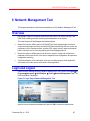
6 Network Management Tool................................................................................................... 85
Overview ............................................................................................................................. 85
Login and Logout ................................................................................................................ 85
Site Tree.............................................................................................................................. 86
Site Tree Structure.......................................................................................................... 87
Device List ...................................................................................................................... 90
Site Control ..................................................................................................................... 92
Searching Devices .......................................................................................................... 94
Device List........................................................................................................................... 95
Service Module List ........................................................................................................ 95
Device List ...................................................................................................................... 96
Client Application .......................................................................................................... 101
Main Menu ........................................................................................................................ 101
View .............................................................................................................................. 101
Tool............................................................................................................................... 102
Information Bar .................................................................................................................. 103
Device Type .................................................................................................................. 103
Alarm List ...................................................................................................................... 104
Device Events ............................................................................................................... 104
System Information ....................................................................................................... 104
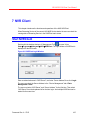
7 NVR Client .......................................................................................................................... 105
Start NVRClient ................................................................................................................. 105
Document Rev A – 07/15
ii
HUS-SWP-32S Client User Manual
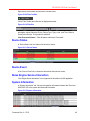
General Statistics .............................................................................................................. 106
Storage Disk Information ................................................................................................... 107
Playback List ..................................................................................................................... 107
Device List......................................................................................................................... 107
Real-time Information ........................................................................................................ 107
Document Rev A – 07/15
iii
HUS-SWP-32S Client User Manual
1 About This Document
This user manual introduces the functions, installation and operations of HUS-SWP-32S
Client which is one of the core components of HUS-SWP-32S IP Security Integration
Platform.
This manual supports HUS-SWP-32S 4.3.0 version.
Special Fonts and Symbols
Italic
Indicates referenced chapter, figure number, page number and etc. In
electronic edition, click it to switch to the corresponding page.
【】
Indicates it is a button, tab or menu item.
Alert the user to the presence of important operating and maintenance
instruction in the literature accompanying the product.
How to Use This Document
Pictures in the manual are for reference only, so please see the actual items.
The products will be updated and the information shall not be distributed.
Please read the book before operation and keep it properly for future use.
The manual has been reviewed and the accuracy is guaranteed. If there is any
uncertainty or controversy, please refer to the final explanation of Honeywell.
Honeywell does not take any responsibility for any consequences caused by
misunderstanding of the manual or improper operations.
Document Rev A – 07/15
1
HUS-SWP-32S Client User Manual
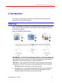
2 Introduction
This chapter provides the general information of HUS-SWP-32S Client and system
requirements for running the components.
Overview
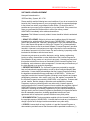
The core components of HUS-SWP-32S IP Video Solution are HUS-SWP-32S and HUSClient, which can implement an effective and reliable IP video surveillance system with
front-end security devices.
Figure 2-1 HUS-SWP-32S Architecture
HUS-SWP-32S – HUS-SWP-32S provides data management, video storage trigger and
event and control services, also provides streaming service, records, stores and playback
videosapplicable to various types of video, intrusion and applicable to various types of
video devices (video encoder, decoder, IP camera, alarm panels….).
HUS-Client – Client of HUS-SWP-32S IP Video Solution supports live video display,
playback from HUS-SWP-32S, maps, alarms management and PTZ of IP front ends.
HUS Client consists of the following components and tools.
Management Tool – used for data synchronization of HUS Client, HUS-SWP-32S,
automatically accessing date from HUS-SWP-32S and providing functions like
connection settings, event viewer, service monitor and etc.
Document Rev A – 07/15
2
HUS-SWP-32S Client User Manual
Client – integrates real time surveillance, history record playback, E-Map and
configuration management, implementing central management of video surveillance
system and device information and alarm event by electronic map.
Network Management Tool – used for monitoring, configuring, and controlling all
HUS-SWP-32S Services, devices, and HUS Client, enabling real-time monitoring
and maintenance of the system.
HUSPlayer is a standalone video player.
Internet Explorer is used for accessing HUS-SWP-32S.
System Requirements
A.
HUS-SWP-32S: HUS-SWP-32S shall require following minimum hardware and operating
system configuration:
1.
Processor: Intel E3-1230 3.2GHz, 64-bit, 4 Threads, 8 MB Cache
2.
System Memory (RAM): 8 GB
3.
Optical Drive: DVD-R
4.
Hard Disk Drives: Enterprise class hard disk 1TB, 3.5" 7200 RPM, SATA, 16 MB
Cache with two partitions
5.
Video Storage: The storage shall be of following specification:
a.
Storage should be configured as local drive in the operating system.
b.
The storage should have recommended IOPS (Input/Outputs Per Second) of
140,000.
c.
It is recommended the video storage be configured in RAID 5/6 to avoid data
loss in event of single HDD failure.
6.
Network Interface Card (NIC): Dual or compatible pair of NICs, with each port
having 1 Gbps capacity.
7.
Human Interface: 102-key keyboard and a mouse pointing device.
8.
Graphics Card: Integrated with 2048MB DDR3 memory and 64-bit memory
interface.
9.
Operating System: Original software CDs and startup installation diskettes for:
a.
Windows® 7 Professional Edition 64-bit
b.
Microsoft® .Net Framework 4.0
c.
Microsoft® Visual C++ 2010 x86 Redistributable Setup
Document Rev A – 07/15
3
HUS-SWP-32S Client User Manual
d.
B.
Direct X 9.0c or newer
HUS-CLIENT: HUS-Client shall require following minimum hardware and operating
system configuration:
1.
Processor: Intel ® i5 750 2.66 GHz
2.
System Memory (RAM): 8 GB
3.
Optical Drive: DVD-R
4.
Hard Disk Drives: 250G,Ensure 20G available space
5.
Network Interface Card (NIC): Dual or compatible pair of NICs, with each port
having 1 Gbps capacity.
6.
Human Interface: 102-key keyboard and a mouse pointing device
7.
Graphics Adapter: NVIDIA 9200 and above, 1GB and above independent
graphic card (HUS Client does not recommend integrated graphic card).
8.
Operating System: Original software CDs and startup installation diskettes for:
a.
Windows® 7 Professional 64-bit
b.
Microsoft® .Net Framework 4.0
c.
Microsoft® Visual C++ 2010 x86 Redistributable Setup
d.
Direct X 9.0c or newer
Document Rev A – 07/15
4
HUS-SWP-32S Client User Manual
3 Installing HUS Client
This chapter introduces how to install and uninstall HUS Client components.
Microsoft .Net Framework 4.0\4.5 must be installed before installing
HUS Client, otherwise the following error occurs:
Installation
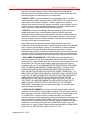
Double click HUSSetup.exe in the installation CD and the following figure is displayed:
Figure 3-1 Package Selection
Click HUS Client Install and the following figure are displayed.
Document Rev A – 07/15
5
HUS-SWP-32S Client User Manual
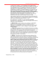
Figure 3-2 Installation Selection
Check the components to be installed (HUS Management Tool is checked, default)
according to the user’s administrative level and operation function.
Normally HUS Management Tool and Client should be installed; while Network
Management Tool is optional.
Keyboard Console should not be installed
Click Destination to specify the directory of installation files. Default: C:\Program
Files\Honeywell\
Click Install to start the installation wizard.
For the first installation, it pops up the following information if Visual C++ Runtime
Libraries have not been installed.
Figure 3-3 Visual C++ Runtime Libraries
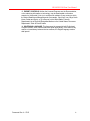
Click Install. When C++ components installation is complete, the wizard will start
installing the selected HUS Client components. A progress bar is displayed during the
installation of each component.
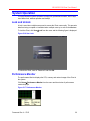
When HUS Client components are installed, shortcuts are created on the desktop.
Document Rev A – 07/15
6
HUS-SWP-32S Client User Manual
Figure 3-4 HUS Client – Desktop Shortcuts
Uninstallation
To uninstall the components, double click “HUSSetup.exe” in the CD and the following
figure is displayed.
Figure 3-5 Uninstall HUS Client Components
Click HUS Client Uninstall.
Figure 3-6 Select Component
It lists all installed components. Check the components to be uninstalled and click
Uninstall. The wizard will uninstall the selected components and they will be removed
from the list when the uninstallation is complete.
Document Rev A – 07/15
7
HUS-SWP-32S Client User Manual
4 Configurations in Management Tool
This chapter introduces how to configure settings in HUS Management Tool before
accessing HUS Client components.
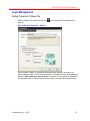
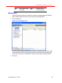
Start Management Tool
Before logging in HUS Client components, you need to add management sites (HUSSWP-32S) in Management Tool for client users to control front-end devices connected to
corresponding HUS-SWP-32S and manage alarms.
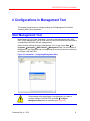
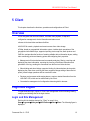
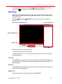
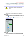
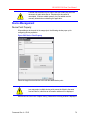
Double click the desktop shortcut of “Management Tool” or open it from Start All
Programs Honeywell HUS Platform Management Tool. The main window of
Management Tool is displayed and a message pops up for the first launch to remind you
to configure HUS-SWP-32S.
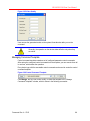
Figure 4-1 Information – Configuring Management Sites
If the message in the above figure is not displayed or you want to
configure another HUS-SWP-32S, open File Configure
Management Sites from the menu bar (see Figure 4-2).
Document Rev A – 07/15
8
HUS-SWP-32S Client User Manual
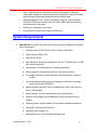
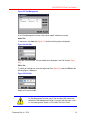
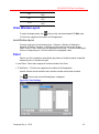
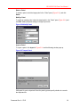
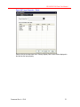
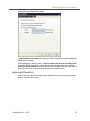
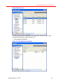
Configuring Management Sites
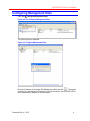
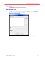
Open File Configure Management Sites.
Figure 4-2 File: Configure Management Sites
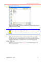
The following figure is displayed.
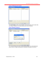
Figure 4-3 Configure Management Sites
Enter the IP address of the target HUS Managerment Sites and click “
”. The system
searches for it and displays its information in the list box below if the HUS-SWP-32S of
the corresponding IP address is running properly.
Document Rev A – 07/15
9
HUS-SWP-32S Client User Manual
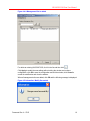
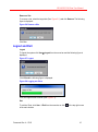
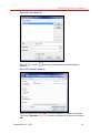
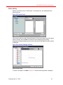
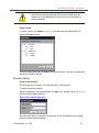
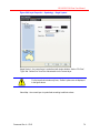
Figure 4-4 A Management Site is added
For delete an existing HUS-SWP-32S, click it in the list and then click “
”.
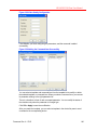
Click Apply to enable the new settings without exiting the window and continue
configuration; click OK to save the configuration and exit the window; click Cancel to
cancel the modification and close the window.
When all management sites are added, click OK and the following message is displayed.
Figure 4-5 Information: Modify Succeeded
Document Rev A – 07/15
10
HUS-SWP-32S Client User Manual
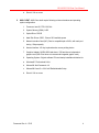
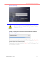
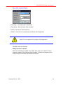
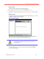
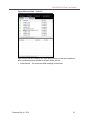
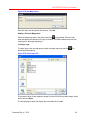
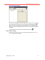
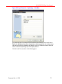
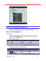
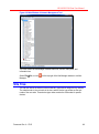
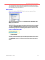
Event Viewer & Services
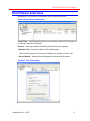
Management Tool includes two components: Event Viewer and Services.
Figure 4-6 Event Viewer and Services
Event Viewer – view and search event logs. In the left pane, right click “Event viewer” or
its sub-items and select “Properties”.
Services – start, stop, restart or refresh the services and view its properties.
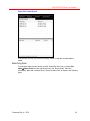
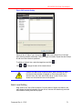
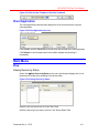
Windows Time – Synchronize the time of the whole system.
User must set Synchronize Time server IP address, for example: 192.168.1.100.
Service Monitor – Supervise the running status of all services in the system.
Figure 4-7 Time Client setting
Document Rev A – 07/15
11
HUS-SWP-32S Client User Manual
5 Client
This chapter describes the functions, operations and configurations of Client.
Overview
Client integrates real-time surveillance, recorded video playback, E-Map and
configuration management, device information and alarm event
Access to front-end video and alarm facilities.
HUS-NVR for search, playback and remote access from video storage.
E-Map: based on geographical information system, includes basic operations of the
geographical information layer; supports importing vector map files, static pictures and
CAD files; and provides the function of creating editable device information layers, adding
video monitoring points and alarming points and configuring their properties.
Management of front-end alarms and commands: analyzing, filtering, receiving and
displaying the alarm information, exporting the local log of the alarm information and
generation of the log, sending the commands from the front end video devices.
Video binding and alarm linkage: supports binding of video and alarm device points,
displaying the video when receiving the alarm; supports linkage setting of alarm device
points, preset linkage operations will be executed in order.
Receives and processes wide-ranging alarms, events or status information from the
HUS-SWP-32S, which can be customized by the Client.
Concentrative management of configuration data using built-in browser.
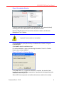
Login and Logout
This part describes login, logout of “Client” and management of sites including creating,
modifying and deleting sites in the login window.
Login and Site Management
Double-click the desktop shortcut for “Client” or open it from
StartProgramsHoneywellHUS PlatformClientClient. The following figure is
displayed.
Document Rev A – 07/15
12
HUS-SWP-32S Client User Manual
Figure 5-1 Client Login
Enter the user name, password and select the site name.
User name and password are specified in Data Management Center.
For how to create users, refer to “User Management” section of “HUSSWP-32S User Guide”.
Click OK. The system begins to load resources and the following figure is displayed:
Figure 5-2 Loading Resources
After the resources are loaded, the main window of Client is displayed (See Figure 5-9 ).
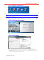
In the login window, user can manage the sites.
To manage the sites in the login window (See Figure 5-1 ), click “Site Management” and
the following figure is displayed:
Document Rev A – 07/15
13
HUS-SWP-32S Client User Manual
Figure 5-3 Site Management
In the “Site Management” window, sites can be added, edited and removed.
Add a Site
To add a site, click Add (See Figure 5-3 ) and the following figure is displayed:
Figure 5-4 Add Site
Enter the IP and click OK. The new added site is displayed in the Site list (See Figure
5-3 ).
Edit a Site
To modify an existing site, select the target site (See Figure 5-3), and click Edit and the
following figure is displayed:
Figure 5-5 Edit Site
Modify the IP and click OK.
In “Site Management” window, only IP can be edited. Site names are
specified in Data Management Center. For how to edit site name, refer
to “User Management” section of “HUS-SWP-32S User Guide”.
Document Rev A – 07/15
14
HUS-SWP-32S Client User Manual
Remove a Site
To remove a site, select the target site (See Figure 5-3 ) and click Remove. The following
figure is displayed:
Figure 5-6 Remove a Site
Click Yes.
Logout and Exit
Logout
To logout the system click User Logout from the menu bar and the following figure is
displayed:
Figure 5-7 Logout
Click OK and the following figure is displayed:
Figure 5-8 Logging out Client
Then, the login window is shown (See Figure 5-1).
Exit
To exit the Client, click User Exit from the menu bar or click
of the main window.
Document Rev A – 07/15
in the top right corner
15
HUS-SWP-32S Client User Manual
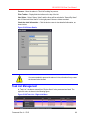
Main Window of Client
The main window of Client is shown below:
Figure 5-9 Main Window
Tool Bar
Function Tabs
There are four function tabs: “Video”, “Search&Playback”, “Map View” and “Map Edit”.
“Rule Client” is not supported in this edition of HUS application. For detailed functions of
each tab, refer to the following chapters in this manual.
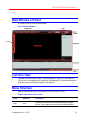
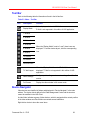
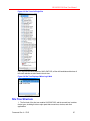
Menu Structure
Refer to the following table for the functions of all menu items in Client:
Table 5-1 Menu Structure of Client
Menu
Submenu
Description
User
Lock
Temporarily lock the user interface and pops up the login
window. Log in again and to return to the interface before
Document Rev A – 07/15
16
HUS-SWP-32S Client User Manual
clicking UserLock.
Setting
Help
Logout
Logout the current user and the Client is closed then the login
window is displayed.
Exit
Exit the Client.
Data
Management
Pop out login window of “Data Management” in explorer. You
can log in the Data Management Center. Refer to related
chapters in “HUS-SWP-32S User Guide”.
Performance
Monitor
View the CPU usage in the pop-up window.
System Tool
Open system components or applications, including HUS
Player (for more details about HUS Player, see “HUS Player”
chapter), AlertConsole….
User-define
Tool
Configure customized shortcut keys of executable
applications. Added shortcuts are showed in Setting Userdefine Tool.
Rule Package
Subscribe
Status
Not applicable for this edition of HUS application.
Alarm Logs
Manage all alarm logs. See “System Information
Management ”.
Reset Window
Layout
Reset the window layout to default mode.
Options
Set the snapshot storage folder, PTZ step, PTZ shortcut key
definition, Bind Camera and Matrix Settings….
About
View version information.
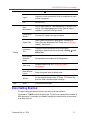
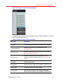
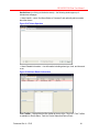
Patrol Setting Shortcut
The patrol setting shortcut is in the top right corner of the main window.
Click Local or TV Wall to select the patrol type. TV Wall is not supported in this edition of
HUS application. For example, click Local to highlight the button and list all local patrols
in the drop-down list.
Document Rev A – 07/15
17
HUS-SWP-32S Client User Manual
Figure 5-10 Patrol Setting
Play a Patrol
Select a patrol in the list and click
to start the patrol. A red point is displayed on the
button “Local” or “TV Wall” when there is a running patrol. The right textbox shows the
name of the running scenario.
Figure 5-11 Running Patrol
For both of the two types, only one patrol can be running at a time.
Pause, Restart and Stop a Patrol
To pause the patrol, click
To stop the patrol, click
. Click
to run it again.
.
Check the Scenarios of Current Patrol
When a patrol is running or paused, click
or
to view the previous or the next
scenario. Performing this operation in a running patrol will cause the patrol to be paused.
In full-screen mode, the toolbar is hidden in the top. Move the mouse
around the window top to show the toolbar.
When a local patrol is running, double-clicking a video window or
manually playing the video (dragging and dropping a video record
from the video list into the window) will cause the patrol to be paused.
Document Rev A – 07/15
18
HUS-SWP-32S Client User Manual
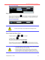
Tool Bar
The toolbar is different in each function tabs, refer to the following chapters for details.
Information Bar
The information bar is on the bottom of the main window, including “Device Alarm”,
“Device Status”, “Task List”, “Device Events”, “Rule Engine Service Interaction” and
“System Information”. For details, see “System Information Management” chapter.
Connection Status Bar
It displays the status of Rule Engine Service, Event Control Service and Current Site in
the status bar. The indicator ahead of each service displays the status of the connection.
Check Connection Status of Service
The Client connects to the Service automatically and the status indicator is displayed in
the bottom right corner.
Figure 5-12 Connection Status
Green – Successfully connected;
Red – Disconnected.
Check Service Information
To view the Rule Engine Service, click the indicator of “Rule Engine Service”. This edition
of HUS application does not support Rule Engine Service connection.
Figure 5-13 Rule Engine Service
To view the Event Control service, click the indicator of “Event Control Service”. System
supports multiple event control services.
Figure 5-14 Event Control Service
To view the current login user, click the indicator of “Current Site”:
Figure 5-15 Current User
Document Rev A – 07/15
19
HUS-SWP-32S Client User Manual
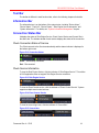
System Operation
This part introduces system operation including lock, performance monitor, HUS Player,
user-defined tool, window operation and tooltips.
Lock and Unlock
A lock is used when multiple users need to access the Client concurrently. This prevents
data from being corrupted or invalidated when multiple users try to write to the database.
To lock the Client, click UserLock from the menu and the following figure is displayed:
Figure 5-16 User Lock
To unlock the Client, enter in “Password” and click OK.
Performance Monitor
The performance Monitor displays the CPU, memory and network usage of the Client in
the system.
Click SetupPerformance Monitor from the menu and the window of performance
monitor displays:
Figure 5-17 Performance Monitor
Document Rev A – 07/15
20
HUS-SWP-32S Client User Manual
To exit the performance monitor, click SetupPerformance Monitor from the menu
again or click
in the right corner of the performance monitor window.
HUS Player
HUS Player is a standalone player for playing video. It is attached in the Client; while the
HUS player can be downloaded from the “Data Management”. To run the HUS Player,
proceed as follows:
Click SetupSystem ToolsHUS Player from the menu and then HUS Player is
displayed:
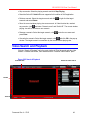
Figure 5-18 HUS Video Player
Tool Bar of Playing List
Video Playing Window
Progress Bar
Tool Bar
Video Playing List
HUS Player contains the following features:
1. Support playing video files in the system.
2. Support quick play (2, 4, 8, 16 or 32 times), slow play (1/2 or 1/4 times), step forward
and step backward.
Find File
Click Find File, select target folder in the pop-up window and click OK. HUS player will
automatically search and put all the.vdo files including those files in the subfolder to the
video playing list.
Add File
Click Add File and select files in the pop-up window, then click OK. All the selected files
will be put in the video playing list.
Delete File
Select the target files in the video playing list, click Delete File.
Document Rev A – 07/15
21
HUS-SWP-32S Client User Manual
Control Panel
Click CtrlPanel to hide or display the control panel.
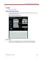
User-defined Tool
To configure customized shortcut keys of executable applications, click Setting Userdefine Tool. And the following figure is displayed:
Figure 5-19 User Defined Tools
To add a new user-defined tool, Click Add and the following figure is displayed:
Document Rev A – 07/15
22
HUS-SWP-32S Client User Manual
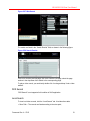
Figure 5-20 Add a New Tool
Enter the “Title” and click
displayed:
beside the “Command” and the following figure is
Figure 5-21 Select the target file
Select the target.exe file, click Open. Then in the window of “Configure User defined
Tools” enter Arguments (Figure 5-20), select the checkbox of “Close on exit” and click
OK.
Document Rev A – 07/15
23
HUS-SWP-32S Client User Manual
To delete user-defined tool, select the target tool from the menu contents and click Delete
(Figure 5-20).
To Move the tool, select the target tool from the menu contents, click Move up or Move
down then click OK (Figure 5-20).
The system only supports adding tool in .exe format.
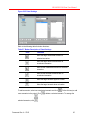
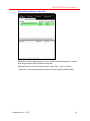
Pane Operation
The panes of function tab “Search& Playback”, “Map View”, “Map Edit”, “Data
Management”, and information tab “Device Alarm”, “Task list”, “Device Status”, “Device
Event”, “Rule Engine Service Interaction” and “System Information” can be exchanged,
floated and relocated.
Click and drag a tab until the following buttons are displayed:
Figure 5-22 Navigation Buttons
Refer to the following table for functions of the navigation buttons:
Table 5-2 Navigation Button
Icon
Description
Locate the target pane to the upper part of the
whole window.
Locate the target pane to the lower part of the
whole window.
Locate the target pane to the left of the whole
window.
Locate the target pane to the right of the whole
window.
Reset window layout and put the target tab to
the end of the tab list.
Exchange the Tab Positions
Document Rev A – 07/15
24
HUS-SWP-32S Client User Manual
Drag a tab and place it on another tab. For example: drag “Search&Playback” and place it
on “Map View” as follows:
Figure 5-23 Exchange the Tab Positions
Drop the tab “Search& Playback” and the location of the two tabs are exchanged as
shown below:
Figure 5-24 Result of Exchanged Tabs
Float the Pane
Drag a tab to any location of the window, as shown in the following figure:
Document Rev A – 07/15
25
HUS-SWP-32S Client User Manual
Figure 5-25 Float the Pane
Drop this tab and the pane of the tab is floating on the main window, as shown in the
following figure:
Figure 5-26 Floating of Panes
If the current monitor is connected with other monitors, the pane can be dragged to other
monitors.
It is not supported to exchange or float the pane of “Video”.
Document Rev A – 07/15
26
HUS-SWP-32S Client User Manual
Manage the Panes Layout
Drag the tab and put it on one of the direction button of
, then drop the tab, the pane is
departed and relocated to the specific direction of the main window. For example,
dragdrop “Search & Playback” to
at the left side, as shown below:
and the pane of “Search & Playback” are relocated
Figure 5-27 Manage the Pane’s Layout
Reset the Window Layout
Perform one of the following methods to reset the window layout:
Dragdrop the moved pane to
. And the target tab is put at the end of the tab list.
Click SetupReset the Window Layout from the menu bar. And the window layout
is reset to default.
Short cut of Function Tab
Click
beside the Patrol Setting Shortcut of the main window and the following figure is
displayed:
Figure 5-28 Menu of the Function Tab Shortcut
Document Rev A – 07/15
27
HUS-SWP-32S Client User Manual
Select the target function tab. Then it switches to the main screen of the target tab.
The Tooltips
Tooltips help you learn the function of each button. If you move the pointer above any
button in the interface, a tooltip with the button name displayed. The tool tips remains
visible until you move your cursor away from the button.
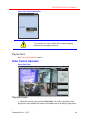
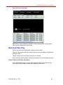
Real-time Surveillance
In the main window of Client, click the “Video” tab.
In the workspace of the “Video” tab, you can view the real-time surveillance video and
video records and configure the device settings. The workspace includes the toolbar,
video playing window, device navigator and My Device and My Scenario.
Figure 5-29 Real-time Surveillance
Document Rev A – 07/15
28
HUS-SWP-32S Client User Manual
Tool Bar
Refer to the following table for information of tools in the left tool bar.
Table 5-3 Video – Tool Bar
Icon
Description
Display Mode
Function
Set the display mode: Local / TV Wall.
TV Wall is not supported in this edition of HUS application.
1-Window
4-Window
6-WindowA
6-WindowB
8-Window
9-window
When the “Display Mode” is set to “Local”, these icons are
displayed. To set the window layout, click the corresponding
icon.
16-Window
36-Window
Surround View
TV Wall Layout
When the “Display Mode” is set to “TV Wall”, this icon is
displayed. TV Wall is not supported in this edition of HUS
application.
Patrol Settings
Configure patrol settings and scenario settings. See “Patrol”
section.
Full Screen
Display the video window in full-screen mode.
Device Navigator
Video devices are classified in folders and displayed in “Device Navigator” in the main
window. The device data is defined in the Data Management Center and the structure
cannot be modified in the HUS Client.
A video folder indicates a group of video devices, which is assigned with a certain position
in the video window area. Each folder can contain several subfolders.
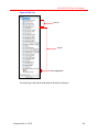
Right-click a device to show the menu items:
Document Rev A – 07/15
29
HUS-SWP-32S Client User Manual
Figure 5-30 Right-click menu of Device Navigator
The right-click menu structure varies depending on device types (the table below does not
cover all possible menu items):
Table 5-4 Right-click menu of Device Navigator
Menu item
Description
Play Video
Play video from the channel in the selected video window.
Play Surround View
Display the surround view of selected device. See
Surround View.
Alternative view
Display the alternative view in the selected video window.
See Play the Alternative View.
Historical Video
Display the historical video search window. You can
search and view the historical video. See Historical Video
Search.
Stop Video
Stop playing the video.
Delete Video
Delete the video or folder (only available in “My Devices”).
Handle Alarm
Process the alarm of the video channel.
Video Quality
Encode Type, Resolution, Video Quality, Frame Rate,
Brightness and saturation (only available for certain device
Document Rev A – 07/15
30
HUS-SWP-32S Client User Manual
types).
OSD Location/Text/Font
Specify the OSD position, edit OSD text or set the text font
(only available for certain encoder types).
Relay Control
Open/Close the relay of the encoder and control the output
signal.
Dialogue
Start/Stop the intercom.
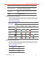
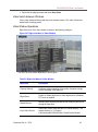
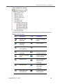
Device Type and Icon Definition
Refer to the following table for all the default device types. Users can customize icons of
those devices in Data Management except “Folder”. For details refer to related chapters
in “HUS-SWP-32S User Guide”.
Table 5-5 Device Types and Icon
Status
Device Type
Non-Status
Unknown
Online
Offline
Playing
Folder
General
Channel
Streamer
PTZ Streamer
Alarm Level and Display Color
Refer to the following table for default color of each alarm displayed in alarm list view and
device tree view, which are defined in Data Manage Center. For details refer to related
chapters in “HUS-SWP-32S User Guide”.
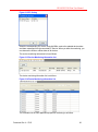
Table 5-6 Alarm Display
Alarm
Level
> 80
> 60
Document Rev A – 07/15
RGB
RGB (255, 34,
34)
RGB (255, 188,
188)
31
HUS-SWP-32S Client User Manual
> 40
> 20
<= 20
RGB (255, 240,
240)
RGB (187, 252,
187)
RGB (153, 252,
153)
Video Window Layout
To select the display mode, click
of the tool bar, and select Local or TV Wall mode.
TV Wall is not supported in this edition of HUS application.
Local Window Layout
There are eight types of local window layout: 1-Window, 4-Window, 6-WindowA, 6WindowB, 8-Window, 9-window, 16-Window and Surround View. When the “Display
Mode” is set to “Local”, these icons are displayed in the tool bar. To set the window layout,
click the corresponding icon. Then the button will be highlighted in blue.
Patrol
Patrol is one of the methods to automatically play videos of multiple channels in specified
windows by turns. It includes two types:
Local Patrol – Patrol video is played in the video window of the Client.
TV Wall Patrol – TV Wall is not supported in this edition of HUS application.
A patrol includes several scenarios and a scenario includes several video channels.
Click
in the tool bar and the following figure is displayed.
Figure 5-31 Patrol Settings
Document Rev A – 07/15
32
HUS-SWP-32S Client User Manual
Patrol Setting
Explode “Local Patrol” and “TV Wall Patrol” in the Patrol Pane, all created patrols are
listed as follows:
Figure 5-32 Set the Patrol
Click a patrol, and then under “Selected Scenarios” list all the scenarios under this patrol.
Select a scenario and click Edit, the following window displaying all the setting
information including window layout and every video device that added into each window
is displayed:
Figure 5-33 Scenario Settings of Patrols
Create a New Patrol
To create a new patrol, click New in Figure 5-31 and the following window is displayed.
Document Rev A – 07/15
33
HUS-SWP-32S Client User Manual
Figure 5-34 Create New Patrol
Patrol Type – Local Patrol and TV-Wall Patrol
Patrol Name – Enter the name of the new patrol
Interval – Set the time interval (second)
Switch ID –Switch ID is not supported in this edition of HUS application.
Switch ID is not supported in this edition of HUS application.
Click OK to save the new patrol.
Adding Scenarios to Patrols:
Select the new patrol just created in the “Patrol” pane, then in the “scenario” lists all
scenarios created in Patrol Setting and My Scenarios. To add a local scenario, select
Local Scenarios or Surround View Scenarios as follows:
Document Rev A – 07/15
34
HUS-SWP-32S Client User Manual
Figure 5-35 Patrol Settings
Refer to the following table for button functions:
Table 5-7 Button Description of Patrol Settings
Icon
Function
Move the target unselected scenario to
selected scenarios.
Move the target select scenario back to
unselected scenarios.
Move all the unselected scenarios to selected
scenarios.
Move all the selected scenarios back to
unselected scenarios.
Move the target scenario upper a location.
Move the target scenario down a location.
To add a scenario, select one unselected scenario and click
more scenarios to the patrol. Click
selected scenarios, click
Document Rev A – 07/15
. Follow this way to add
to delete a selected scenario. To arrange the
.
35
HUS-SWP-32S Client User Manual
Delete a Patrol
To delete a patrol, select the target patrol in the “Patrol” pane (Figure 5-31 ) and click
Delete.
Modify a Patrol
To modify an existing patrol, select the target patrol in the “Patrol” pane (Figure 5-31) and
click Edit. Modify the patrol settings in the pop-up window.
Figure 5-36 Modify Patrol
Import a Patrol
To import a patrol, click Import in Figure 5-31 and the following window pops up.
Figure 5-37 Import Patrol
XML patrol file can be imported. Select the patrol type and specify whether to overwrite
the duplicated file.
Document Rev A – 07/15
36
HUS-SWP-32S Client User Manual
Some devices cannot be displayed if the devices configured for the
current user in Data Management Center do not cover all devices in
the imported patrol.
Export a Patrol
To import a patrol, click Export in Figure 5-31 and export the patrol file as XML file.
Figure 5-38 Export Patrol
Check the target patrol and click Export. Specify the directory in the pop-up window and
the patrol is saved as XML file.
Scenario Setting
Create a new Scenario
There are two type of scenario: Local Scenario and TV Wall Scenario.
To create a new local scenario:
Select a local patrol in the patrol pane and click New in the “Scenario” pane (Figure 5-31 )
and the following window pops up.
Figure 5-39 Create New Scenario
Enter the name of the new scenario, set the switch ID and click OK to save the setting,
and the following figure is displayed:
Document Rev A – 07/15
37
HUS-SWP-32S Client User Manual
Figure 5-40 New Scenario Settings
Select the window layout on the top and the selected one is highlighted in blue as follows:
Figure 5-41 Select the Window Layout
Drag video devices from the Device Navigator to corresponding windows and click OK.
To create a TV Wall scenario:
TV Wall is not supported in this edition of HUS application.
Document Rev A – 07/15
38
HUS-SWP-32S Client User Manual
Delete a Scenario
To delete a scenario, perform one of the following methods:
Select the target one in the “Scenario” pane and click Delete (Figure 5-31).
In “ My Scenario”, delete the scenarios, see “My Device and My Scenario” section on page
47
Modify a Scenario
To modify an existing scenario, select the target in the “Scenario” pane (Figure 5-31) and
click Edit. The following window is displayed:
Figure 5-42 Modify Scenario
Video devices in the left pane can be dragged into windows. For a TV-Wall patrol, the
video device should be compatible with the corresponding decoder.
To modify the scenario name, see “My Device and My Scenario”
section on Page 47.
To delete the video device in a window, right-click the window and select Delete as
shown in the following figure.
Document Rev A – 07/15
39
HUS-SWP-32S Client User Manual
Figure 5-43 Delete Video Device
The scenarios only can be edited when no patrol is playing
otherwise error message will pop up.
Play the Patrol
See “Patrol Setting Shortcut” section.
Video Control Operation
Figure 5-44 Video
Playing the Video
Right-click a device group and select Play Video. The videos in the folder will be
played in the video windows (the videos in its subfolder will not be played). Right-click a
Document Rev A – 07/15
40
HUS-SWP-32S Client User Manual
video channel and select Play Video and the video will be played in the currently selected
window.
Click a video channel in the Device Navigator and drag and drop it into a video window.
The video of the channel will be played in the window.
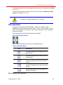
Surround View
Surround View is a special video playing window layout. In a surround view, this video of
the specific device is playing in the centre and the other surround video can be configured.
Every video device can be configured one surround view scenario (See Figure 5-45).
Every user has the authority to play the surround view. To configure
the surround view, the user must be assigned the authority. Refer to
“User Management” section of “HUS-SWP-32S User Guide”.
To play the surround view:
Right-click the target video device in the device navigator, select Play Surround View.
To figure the surround view:
Right-click the target video device in the device navigator, select Configure Surround
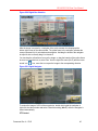
View. The video of target device is playing in the centre as follows:
Figure 5-45 Surround View
Drag other video devices in the device navigator to the surround windows and click
on the tool bar to save the settings. The surround view is saved as a surround view
scenario and can be used in Patrol Setting.
Play the Alternative View
Document Rev A – 07/15
41
HUS-SWP-32S Client User Manual
Each video device can be configured only one alternative view. The alternative device is
related with the target device. For example, if the target device is abnormal, it will play the
video of the alternative device.
The alternative view is configured in “Adding Devices” in Data
Management. Refer to “Adding Devices” section of “HUS-SWP-32S
User Guide”.
Perform one of the following methods to play the alternative view:
Right-click the target video device and select Alternative View.
Right-click the target device video playing window and select Alternative View.
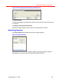
Searching Video
In the video list, you can search videos by entering the information in the “Search” field
and clicking
.
The target videos are highlighted with green, otherwise a window pops up showing that
no result is available. Keep clicking
to highlight the video one by one.
Figure 5-46 Video Search
Stopping Video
Right-click the target video device in the Device Navigator and select Stop Video.
Document Rev A – 07/15
42
HUS-SWP-32S Client User Manual
Right-click the playing window and select Stop Video.
Video Switch between Windows
Click a video window and drag and drop it into another window. The video of these two
windows will exchange places.
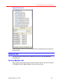
Video Window Operations
Right-click menu of the video window is shown in the following configure:
Figure 5-47 Right-click Menu of Video Window
The menu structure varies depending on device types.
Table 5-8 Right-click Menu of Video Window
Menu Item
Description
Property Settings
Configure settings including Video quality, character overlap,
Device recording, OSD and so on.
Digital Zoom
Enable or disable digital zoom. When digital zoom is disabled
PTZ zoom is enabled.
Manual Record
Manually start recording and specify the Streaming Service for
storing the video files.
Local Video Record
Record the current video and save it in a local directory. The
default directory is “C:\Program
Files\Honeywell\HUSClient\Video Client\DownloadFolder”
Document Rev A – 07/15
43
HUS-SWP-32S Client User Manual
Snapshot
Take a snapshot of the video image and the image is saved in
“C:\Program Files\Honeywell\HUSClient\Video Client\Pic”. To
modify the directory, select SettingOptions.
Full Screen
Display the video window in full-screen mode.
Close Video
Stop the video playing in the current window.
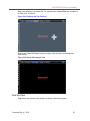
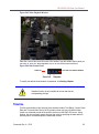
Digital Zoom
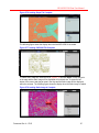
Digital zoom allows viewing the desire image in a larger view by zooming the image
digitally. Right-click the video window and check Digital Zoom as the zoom mode:
Figure 5-48 Digital Zoom
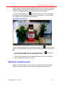
In the video window, move the cursor to the left bottom corner, and the video control tool
bar is displayed including zoom in, zoom out, snapshot, dialogue, local record and manual
record as follows from left to right:
Figure 5-49 Digital Zoom Control Panel
To zoom in the target area of video, click and drag in the playing video, and then this area
is highlighted with red line as follows:
Document Rev A – 07/15
44
HUS-SWP-32S Client User Manual
Figure 5-50 Digital Box Selection
After the image is zoomed in, a navigator of the entire camera view, displays at the
bottom right corner of the video window. The yellow frame in the navigator indicates the
zoomed area and it is for orientation and navigation. And drag the board of the navigator
to adjust its size or directly drag it to relocate it:
You can drag the yellow frame to move the image, or drag the boarder of the yellow frame
to zoom in or zoomed out; or select “Pan” from the right-click menu (Alt+P) and the cursor
turned in to
icon, move the icon to pan the image to the corresponding direction.
Figure 5-51 Digital Navigator
To restore the image of 100% of the normal size, double-click inside the navigator or
right-click the video window and select “Reset the scaling (Alt+ Z)” while the navigator is
closed automatically.
PTZ Control
Document Rev A – 07/15
45
HUS-SWP-32S Client User Manual
To select PTZ Control, right-click the video playing window and uncheck Digital Zoom
(Figure 5-48). Users can select either Digital Control or PTZ control.
PTZ control is used for adjusting PTZ movement and setting the focus, aperture and
preset bit of the camera. It is only available when the property of the device channel is set
as “Dome” and a dome is directly connected to the channel.
Common PTZ control can be achieved directly in the video window. For example, move
the focus to the right edge while the focus changes into
and click the mouse for the
PTZ to turn right. Video Control toolbar (Figure 5-52) includes all PTZ operations.
Preset settings:
Set a preset point: Click
on the video control toolbar, enter the “Present Number”
and click OK. The present location of the view is set as a present point.
Locate to a present: Click
on the video control toolbar, enter the “Present Number”
and click OK. The present view is set to the target present point.
Delete a present point: Click
Number” and click OK.
on the video control toolbar, enter the “Present
Video Control Toolbar
Select a video window which is playing video and move the focus to the bottom of the
window, so the video control toolbar is displayed.
Figure 5-52 Video Control Toolbar
You can perform related operations using the buttons, including Zoom in and out, preset
point settings, Video Quality and so on.
The toolbar function varies depending on the device and user
authorities.
Switching to 1-window mode
Double-click a video window to switch to 1-window mode. Double-click it again to return to
the previous display mode.
View Full-screen
Right-click a video window and select “Full Screen” to enlarge the scale of all video
windows to full-screen. To return to the previous display mode, right-click it and select
“Exit Full Screen”.
Instant Playback
Document Rev A – 07/15
46
HUS-SWP-32S Client User Manual
Instant Playback is used for playing the latest 30 seconds video. It is used for monitoring
emergent situation. This function is enabled by default. If the user wants to disable this
function, click SettingsOptions and uncheck “Enable Instant Playback”.
View the instant playback: Click
on the bottom right corner of the video window.
And it displays instant playback while the left top corner displays “Live” and “Playback”.
The “Playback” label is highlighted in blue as follows:
Figure 5-53 Instant Playback
Store the instant playback video: In the playback window, click
in the right bottom
corner. In the pop-up window, enter the file name and specify the file directory and click
OK.
Close the instant playback video: In the playback window, click
right corner and click OK to close the instant playback video.
in the bottom
Switch to the real-time video: In the playback window, click “Live” on the top left
corner and it switches to the real time video.
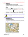
My Device and My Scenario
Below the “Device Navigator”, there are two panes: “My Devices” and “My Scenario”,
where you can create a device/scenario folder and drag devices/scenarios into it.
Document Rev A – 07/15
47
HUS-SWP-32S Client User Manual
Figure 5-54 “My Devices” and “My Scenario”
Refer to the following tool bar introduction:
Table 5-9 Tool Bar
Icon
Function
Add folders or
scenarios.
Delete folders
or scenarios.
Overwrite
scenario.
Rename
folders or
scenarios.
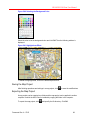
Manage My Devices
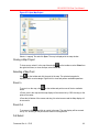
Add a folder: Select a document in” My Devices”, click
name and press Enter on the keyboard.
Delete a folder: Select the target folder. Click
Delete.
Rename a folder: Select the target folder, click
folder and then press Enter on the keyboard.
and enter the document
or right-click target folder and select
and enter the new name of the
Add devices to a folder: Drag a device from the “Device navigator” to the target folder
and drop.
Delete devices in the document: Select the target device, click
folder and select Delete.
or right-click the
Manage My Scenarios
Play a scenario: Right-click the target scenario and select Play the scenario.
Document Rev A – 07/15
48
HUS-SWP-32S Client User Manual
Stop a scenario: Select the playing scenario and click Stop Playing.
Reset the Switch ID: Switch ID is not supported in this edition of HUS application.
Delete a scenario: Select the target scenario and click
scenario and select Delete.
or right-click the target
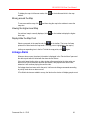
Store the current window playing view as a scenario: In Video function tab, unselect
any scenario, click
and enter “Scenario name” and “Switch ID”. The current window
playing view will be stored as a new scenario.
Rename a scenario: Select the target scenario, click
press Enter.
, enter the new name and
Overwrite the scenario: Select the target scenario, click
and click OK in the pop-up
window. The target scenario is overwritten by the current window playing view.
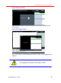
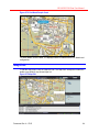
Video Search and Playback
Click the “Search & Playback” tab in the main window of Client to search and play video
records. It includes the toolbar, video window and the “Historical Video Search” pane.
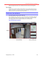
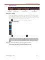
Figure 5-55 Search & Playback
Video Window
Historical Video Search
Toolbar
Timeline
Document Rev A – 07/15
49
HUS-SWP-32S Client User Manual
Toolbar
See “Tool Bar” section.
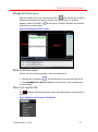
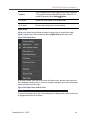
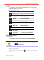
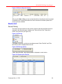
Historical Video Search
“Historical Video Search” pane contains four tabs: “Web Search”, “DVR Search”, “Local
Search” and “Search By Alarm”.
Figure 5-56 Historical Video Search
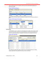
Web Search
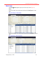
To search video records in the HUS-NVR, click the “Web Search” tab and set the
searching criteria. Click Search to start searching and a progress bar is displayed.
Document Rev A – 07/15
50
HUS-SWP-32S Client User Manual
Figure 5-57 Web Search
The results are listed in the “Search Results” field, as shown in the following figure:
Figure 5-58 Search Results
Click << to view the previous page; click >> to view the next page; select the page
number in the drop-down list to switch to the corresponding page.
To play a video record, you can directly double-click it or drag and drop it into a video
window.
DVR Search
“DVR Search” is not supported in this edition of HUS application
Local Search
To view local video records, click the “Local Search” tab. It includes three tabs:
Store Path – The records are listed according to the store path;
Document Rev A – 07/15
51
HUS-SWP-32S Client User Manual
Figure 5-59 Local Search – Store Path
Right-click a record to display the pop-up menu, select “Add a new store path” or “delete
an existing store path (Keep at least one store path).
Right-click one record from the “Search Result”, select “Play”, “Copy” or “Delete”.
Task List – The records are listed according to the task (recording and download).
Document Rev A – 07/15
52
HUS-SWP-32S Client User Manual
Figure 5-60 Local Path – Task List
Right-click the task and it displays the menu items by which you can end or delete the
task; to perform the same operation to all tasks, select “All” first.
Instant Record – The records are listed according to stored time.
Document Rev A – 07/15
53
HUS-SWP-32S Client User Manual
Figure 5-61 Instant Record
In this window, the user can check the property, delete or copy the recorded instant
record.
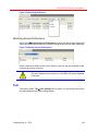
Search by Alarm
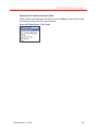
To view alarm video records, directly click the “Search By Alarm” tab; or select View
VideoHistory Video from the right-click menu in the “Device Alarm” tab of the
“Information” pane and it switches to the “Search By Alarm” tab, as shown in the following
figure.
Document Rev A – 07/15
54
HUS-SWP-32S Client User Manual
Figure 5-62 Search By Alarm
Right-click the video record and it displays the menu items by which you can play the
video record or download the video record.
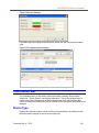
Historical Video Play
Perform one of the following methods to play the historical video:
Right-click the target record of the Search Result list and selects Play, or double-clicks
the target record.
Drag the target record of the Search Result list to a window.
Users can do the relative operation and timeline operation in the video playback window.
Video Playback Window Operation
In the video playback window, you can take snapshots, display in full screen or close
video, right-click the playback window and it displays the menu items:
Document Rev A – 07/15
55
HUS-SWP-32S Client User Manual
Figure 5-63 Video Playback Window
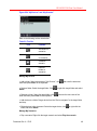
Place the cursor at the lower left corner of the window, from the hidden control panel you
can zoom in, zoom out, take snapshots, turn on or turn off the sound as follows:
Figure 5-64 Hide Control Panel
Turn on/Turn off the Sound
Zoom In
Zoom Out
Snapshot
To modify the default stored location of snapshots, click SettingOption.
Snapshot function is only available for a user that has the
corresponding privilege.
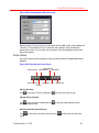
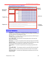
Timeline
Timeline at the bottom of the historical video window includes Time Range, Control Panel,
Date and Time and Video Record. HUS provides a clear overview of historical video
record over extended periods of the specific devices on HUS-SWP-32S server. Using
timeline, the user can easily search and play the video by specifying the date and time,
frame-by-frame, at different speeds, forward and reverse.
Document Rev A – 07/15
56
HUS-SWP-32S Client User Manual
Figure 5-65 Timeline
Time Range
Control Panel
Date and Time
Video Record
Scaling the Timeline
A time range is displayed in the lower part of the timeline window. The number indicates
the timescale: 5M (5 minutes), 15M (15 minutes), 30M (30 minutes), 1H (1 hour), 5H (5
hours), 15H (15hours), 30H (30 hours), 60H (60 hours), 30D (30 days) and 60D (60 days).
Perform one of the following methods to set the time range:
Click
, select the time range from the pop-up menu as follows:
Figure 5-66 Timeline Scale
Click
to switch to the next time range or click
to switch to the previous time
range.
Place the cursor on the timeline and move the mouse's scroll wheel to switch the time
range. Move the mouse's scroll wheel forward and release to switch to the previous time
range; move the mouse's scroll wheel backward and release to switch to the next time
range.
Playing the Historical Video by Specifying Date and Time
Click the range of date and time, a calendar is displayed as follows:
Document Rev A – 07/15
57
HUS-SWP-32S Client User Manual
Figure 5-67 Playing the Historical Video by Specifying Date and Time
Select the target date and time, click OK to play the historical video.
Setting the Video Play Time by Dragging the Timeline
Drag the timeline rightward or leftward and release the mouse to play the video record.
Drag rightward to play previous video record; drag leftward to play next video record.
Video Record
Color-coded parts on the timeline are used to indicate information of the current device.
Black (blank area) – No video.
Blue – Video is recorded on HUS-SWP-32S.
Grey – Video is recorded on HUS-SWP-32S but video task (HUS-NVR) is failed.
Viewing Video Information
Place the cursor on the blue part and it displays the device name.
Click the grey part, and it displays the alarm information for record failure. (Currently it
only displays record failure of HUS-NVR.)
Downloading the Record to Local
Right-click the blue part and select “Download”. And the following window is displayed:
Document Rev A – 07/15
58
HUS-SWP-32S Client User Manual
Figure 5-68 Downloading the Record to Local
Select the begin Time and end time to download and click OK. A task will be displayed in
“Task list” of “Local Research” tab in” Historical Video Search” which indicates the
download is correct. You can check the information of the downloading record and the
download progress.
Control Panel
Use control panel to precise playback, frame-by-frame playback, and adjustable-speed
playback.
Figure 5-69 Video Record Control Panel
Previous Frame
Increase Speed
Reduce Speed
Next Frame
Previous Record
Play Speed
Reverse
Play
Next Record
Playing the Video
Click
to play video. The icon changes to
. Click this icon again to stop.
Playing Frame-by-frame
Click
to skip one frame forward and click
selected historical video.
to skip one frame backward of the
Next Record and Previous Record
Click
record.
to skip to the next video record and click
Document Rev A – 07/15
to skip to the previous video
59
HUS-SWP-32S Client User Manual
Adjustable-speed Playback
Click
to switch to the previous slower level speed, or click
to switch to the next
faster speed level then click
to play or click
to play in reverse.
playing speed. The speeds range from 0.25X to 64X.
indicates the
The following devices support Reverse, Next Frame and
Previous Frame:
Super HD, AniraX and Fisheye.
Map View
In the main window of Client, click the “Map View” tab.
The “Map View” workspace provides central management of alarm points in a map view,
including the toolbar, map window, map preview and map list.
Figure 5-70 Map View
Toolbar
Refer to the following table for information of tools in the left tool bar and at the bottom of
the “Map List”.
Document Rev A – 07/15
60
HUS-SWP-32S Client User Manual
Table 5-10 Map View – Toolbar
Icon
Name
Function
Select
Select device point or link point in the map.
Zoom In
Zoom in the map.
Zoom Out
Zoom out the map.
Full Extent
Display the map in the original scale.
Pan
Move around the map to view all areas.
Parent Map
Display the previous map view.
Open Map
Open a map project.
Close Map
Close the map project.
Close All
Close all opened projects.
Point Filter
Display the icons of link points of the
selected map.
Map Operations
Opening a Map Project
Click
on the toolbar and the following window pops up:
Document Rev A – 07/15
61
HUS-SWP-32S Client User Manual
Figure 5-71 Open Map Project
Select a “.mapproj” file and click Open. The map is displayed in the map window.
Closing a Map Project
To close a map, select it in the map list and click
on the toolbar or select Close from
the right-click menu; to close all maps, select Close All.
Selecting a Map Point
Click
on the toolbar and click the point in the map. The selected map point is
displayed within a red rectangle. Right-click it to view and perform available operations.
Zoom In
To zoom in on the map, click
below:
on the toolbar and perform one of the two methods
Click a point in the map and the map display will be zoomed in by 150% focusing on the
point as the center.
Press the left button of the mouse and drag it to select an area and the Map display will
be zoomed in.
Zoom Out
To zoom out, click
and click at a point in the map. The map display will be zoomed
out by 75% focusing on the point as the center till its original size
Full Extent
Document Rev A – 07/15
62
HUS-SWP-32S Client User Manual
To display the map in full-screen mode, click
window.
on the toolbar and click in the map
Moving around the Map
To move around the map, click
map view.
and then drag the map in the window to move the
Viewing the Higher-level Map
If a sub-level map is currently displayed, click
level map.
on the toolbar to display the higher-
Display/Hide the Map Point
Select a map node in the map list and click
on the toolbar. The icons of all map
points will be listed under the map node. The map point is highlighted in the map by
clicking corresponding icon in the list. To hide the map points, click
again.
Linkage Alarm
When an alarm occurs, the alarm information is displayed in the “Device Alarm” pane and
the device point which is linked with the alarm device flickers.
If the point has a binding video, a video window will pop up playing the video when an
alarm occurs. When the alarm has been processed, it will play the next alarm video;
otherwise it will continue playing the current video.
If a linkage alarm has been set for the point, it will execute linkage commands according
to priority levels when an alarm occurs.
If Pro-Watch devices are added to a map, the label on the device will display people count
Document Rev A – 07/15
63
HUS-SWP-32S Client User Manual
Figure 5-72 Pro-Watch People Count
To check details, click the label. The displayed detail is related with the Pro-Watch card
configuration.
Map Edit
To edit the map project, click the “Map Edit” tab. The “Map Edit” workspace includes the
toolbar, map window, map list and layer list.
Figure 5-73 Map Edit
Document Rev A – 07/15
64
HUS-SWP-32S Client User Manual
Toolbar
In the “Map Edit” tab page, the toolbar includes several icons which are the same as in
the “Map View” tab and the following ones.
Table 5-11 Map Edit – Toolbar
Icon
Name
Function
Add Device Point
Add a device point in the map.
Add Map Point
Add sub-level map point.
New Map
Create a new map project.
Remove Map
Delete the map project.
Save Map
Save modifications of the map project.
Export Map
Export the map project.
Add Layer
Add a layer to the current map project.
Remove Layer
Delete the current layer.
Layer Property
Pop up layer property setting window.
Editing Map Project
New Map Project
In the “Map Edit” tab, you can create a new map project or modify existing ones.
When creating a new map project or modifying an existing map project,
click
to save the settings.
Creating a New Map Project
Select the “Map Root” in the map list and click
pops up.
Document Rev A – 07/15
on the toolbar. The following window
65
HUS-SWP-32S Client User Manual
Figure 5-74 New Map Project
Enter the map name and specify the directory. Click OK.
Adding a Sub-level Map project
Select the target map node in the map list and click
on the toolbar. Enter the map
name and specify the directory in the pop-up window. Click OK to add the new sub-level
map project to the target map project.
Loading a Layer
To load a layer to the new map project, select the target map node and click
following window pops up:
. The
Figure 5-75 Select Layer File
Three types of layer file are supported: shape file, AutoCAD 2000 and static image. Select
the file and click Open.
The following figure shows the display when the shape file is loaded.
Document Rev A – 07/15
66
HUS-SWP-32S Client User Manual
Figure 5-76 Loading Shape File Complete
The following figure shows the display when the AutoCAD 2000 file is loaded.
Figure 5-77 Loading CAD 2000 File Complete
To load a static image file, select the file in Figure 5-75 and click Open. Click at the point
in the map and the static image will be displayed at its original size. Or press the left
button of the mouse and drag an area in the map and the static image will be displayed
within the set area. The following figure shows the display when the static image is loaded.
Figure 5-78 Loading Static Image is Complete
Document Rev A – 07/15
67
HUS-SWP-32S Client User Manual
Adding Map Points
Link points includes device points and sub-level map points.
The layout of the device points shows the distribution of the front-end devices in the
system.
The layout of the sub-level map points shows the layout of the sub-level maps in the
map project.
To add a device point, click
and then click the point in the map where you want to
place the device. Configure the device properties (see “Device Point Property” section) in
the pop-up window and the device icon will be displayed at the target place.
To add a sub-level map point, click
and then click the point in the map where you
want to place the sub-level map. Configure the properties of the sub-level map in the popup window and the icon of the sub-level map will be displayed at the target location.
Sub-level map points can only be added in a map project which contains
sub-level maps.
Adding Map Highlight Area:
This function is to highlight target area,
To add a highlight area, drag on the map and a red transparent marquee is displayed as
below:
Figure 5-79 Adding Highlight Area
Drop the mouse, the follow window is displayed:
Document Rev A – 07/15
68
HUS-SWP-32S Client User Manual
Figure 5-80 Selecting the Background Color
Select the color to be the background color and click OK. Then the following window is
displayed:
Figure 5-81 Highlight Area Effect
To delete the highlight area, click on the area and press Enter.
Saving the Map Project
After finishing operations and settings in a map project, click
to save the modifications.
Exporting the Map Project
A map project can be exported as a folder and the map project can be applied in another
computer in which the HUS Client is installed by copying the folder in the computer.
To export the map project, click
Document Rev A – 07/15
and specify the file directory. Click OK.
69
HUS-SWP-32S Client User Manual
A stored map document can be copied, but don’t modify any file in the
document nor add, delete files in. Otherwise this document is
unavailable. If files are added manually, the files added must be
manually deleted when uninstalling the application.
Device Management
Device Point Property
When adding a device point in the map project, the following window pops up for
configuring device properties:
Figure 5-82 Device Point Property
Select the target front-end device to link with the added device point.
In a map project, multiple device points cannot be linked to the same
front-end device; otherwise an information window will be displayed.
Double-click the icon in the “Graphic Setting” field and the following window is displayed.
Document Rev A – 07/15
70
HUS-SWP-32S Client User Manual
Figure 5-83 Select the Icon
Select a file and click Open. The new icon is displayed in the “Graphic Setting” field in the
“Device Point Property” window.
If “Set as default image” is checked, the icon will be applied to newly
added device points which link with the devices of the current type.
In the “Style Setting” field, click “None” or “Outline” to select whether or not to apply
borders to the icon; click “Color” to set the color of the borders in the pop-up window.
For a non-video device, a video binding can be set to the device by selecting in the dropdown list of “Video Binding”. . When alarms come in, the link video will popped up.
Setting Status Icon
In the “Device Point Property” window (Figure 5-82), click Set Status Image and the
following window pops up.
Document Rev A – 07/15
71
HUS-SWP-32S Client User Manual
Figure 5-84 Status Icon Setting
To set an icon to a status type, select a device type in the drop-down list of “Device Type”
and it lists all status of the device if it has any. Select one of the statuses and click
.
Select an icon file in the pop-up window and click Open. The icon is displayed in the
window and the status is highlighted with light blue, so the icon has been successfully set
to the status.
To delete the icon set to a status, select the status in the list and click
.
Alarm Interlock Setting
When receiving an alarm, the device can execute preset operations in order. In Figure
5-82 , click the “Interlock Setting” tab.
Document Rev A – 07/15
72
HUS-SWP-32S Client User Manual
Figure 5-85 Interlock Setting
Select an item in “Alarm Type” list and click
to add a new interlock item in the right
pane showing available commands. Select the target commands. Repeat the above steps
to add more alarm interlock operations.
To delete an interlock item, select the target item and click
Click
or
.
to change the order of the interlock items.
A device can add at most 4 interlock items. When receiving an alarm,
the interlock video window will popped up. If there are more than 4
interlock items, the video winnow will pop up in order. But the video
window can be locked and can not be replaced.
Alarm Level Setting
Drag “Alarm Level” bar to filter the alarms. Only the alarms of higher level than the set
value trigger the interlock operation; the rest do not, however the related map points will
flicker and the binding video will be played.
Document Rev A – 07/15
73
HUS-SWP-32S Client User Manual
Layer Management
Setting Properties of Shape File
Select a Shape file in the layer list and click
pops up:
on the toolbar. The following window
Figure 5-86 Layer Properties – General
Check/uncheck “Display” to set whether the present layer displays in the map or not.
When setting the scale, if “Show layer at all scales” is checked, the layer will be displayed
always; if “Don’t show layer when zoomed:“ is checked, the layer will not be displayed if
the map scale is either out beyond the minimum scale or in beyond the maximum scale.
Document Rev A – 07/15
74
HUS-SWP-32S Client User Manual
Figure 5-87 Layer Properties – Fields
Select a field in the drop-down list of “Primary Display Field”, which will be displayed in
the label as the layer property.
Document Rev A – 07/15
75
HUS-SWP-32S Client User Manual
Figure 5-88 Layer Properties – Symbology – Single Symbol
Single Symbol – the current layer is symbolized with single attribute. Set the “Fill Color”,
“Type” and “Outline Size” for all the characteristics in the current layer.
For the layer that includes only lines, “Outline” options are not displayed
in the figure above.
Value Map – the current layer is symbolized according to attribute values.
Document Rev A – 07/15
76
HUS-SWP-32S Client User Manual
Figure 5-89 Layer Properties – Symbology – Value Map
First, select the field. For example, when symbolizing the road layer, select road class in
Field, click Add all and the system will generate a symbology style for the existing unique
value of the current layer randomly and display it in the list. Double-click one of them and
set the customized symbology style in the popup window.
Click the “Label” tab, as shown in the following figure:
Document Rev A – 07/15
77
HUS-SWP-32S Client User Manual
Figure 5-90 Layer Properties – Label
If Label features in this layer is checked and a field is selected, the selected label field
will be used in this layer.
When specifying the range of scales, if Use the same scale range as the feature layer
is selected, the label will display in the map with the same scale as the layer; if Don’t
show layer when zoomed: is selected, the label will not display when the scale range is
either out beyond the minimum scale or in beyond the maximum scale.
Image Layer Operations
In the “Layer List”, right-click the layer and it displays the menu items, by which you can
perform operations to the layer.
Document Rev A – 07/15
78
HUS-SWP-32S Client User Manual
Figure 5-91 Right-click Menu of Image Layer
System Information Management
The system information pane contains six tabs: Device Alarm, Task List, Device Status,
Device Event, Rules Engine Service Interaction and System Information.
Device Alarm Management
Device Alarm
Only information about the latest 2000 alarms are listed in “Device Alarm” and the rest
can be viewed in Setting Alarm Logs; the alarm information are highlighted with
different colors according to their levels.
Figure 5-103 Device Alarm
Right-click an alarm and the menu is shown as below.
Figure 5-104 Device Alarm – Right-click Menu
Document Rev A – 07/15
79
HUS-SWP-32S Client User Manual
Process – Move the alarm to “Task List” waiting for process.
Filter Toolbar – Display/hide the toolbar on the top of the list.
View Video – Select “History Video” and the focus will be switched to “Search By Alarm”
tab of “Historical Video Search” in the right pane if there are videos recorded.
Check the detail Information – Click the device name to view detailed information, as
shown below:
Figure 5-105 Alarm Details
It is recommended to process the alarms in time; otherwise it may cause
the channel to be blocked.
Task List Management
In “Task List”, the alarms moved from “Device Alarm” to be processed are listed. The
right-click menu is shown in the following figure:
Figure 5-106 Task List – Right-click Menu
Document Rev A – 07/15
80
HUS-SWP-32S Client User Manual
Handle Alarm (or clicking on the device name) – the following window pops up. It
includes two tab pages:
Alarm Handle – check “Set Alarm Status to Processed” and optionally add comments
about the alarms.
Figure 5-107 Alarm Operation
Alarm Related Information – view information including alarm type, level, and time and
so on.
Figure 5-108 Alarm Related Information
Filter ToolBar – Display/Hide the filter toolbar at the top of the “Task List”. Filter ToolBar
is available for Device Alarm, Task List, Device Status and Device Event.
Document Rev A – 07/15
81
HUS-SWP-32S Client User Manual
Right-click a device status and the menu is shown below:
Figure 5-109 Filter ToolBar
Check Filter Toolbar and a filter bar is displayed as below:
Figure 5-110 Filter Bar
Information can be filtered by Device, Device Type, Type, Level, Last Time, Detail or
EventControl Service. Fuzzy search is available.
Clear Processed Alarms – Clear all alarms marked as “Processed”.
Device Status
In “Device Status” tab, the status of all devices is shown.
Figure 5-111 Device Status
Device Event
In the “Device Event” tab, it shows the information about device events.
Rules Engine Service Interaction
“Rule Engine Server Interaction” is not supported in this edition of HUS application.
System Information
In “System Information” tab, it shows the operation information between the Client and
HUS-SWP-32S in the system and abnormal information.
Figure 5-112 System Information
Document Rev A – 07/15
82
HUS-SWP-32S Client User Manual
Alarm Logs
Click SettingAlarm Logs and it pops up the “Alarm Logs” window (Figure 5-).
Search
In the “Device Alarm” tab, input the search criteria and click View Report to view the
result.
Figure 5-113 Search – Device Alarm
In the “Device Operation” tab, input the search criteria and click View Report to view the
result.
Figure 5-92 Search – Device Operation
Document Rev A – 07/15
83
HUS-SWP-32S Client User Manual
Exporting Device Alarm and Operation Data
Select a format in the drop-down list of “Export” and click Export to save the device alarm
and operation data as a file of the specified format.
Figure 5-93 Export Alarm – File Format
Document Rev A – 07/15
84
HUS-SWP-32S Client User Manual
6 Network Management Tool
This chapter describes the functions and operations of HUS Network Management Tool.
Overview
Net Manager monitors, configures, and controls HUS-SWP-32S Service, devices, and
HUS Client, enabling real-time monitoring and maintenance of the system.
The main functions of Net Manager are listed as follows:
Monitor the online or offline status of HUS-SWP-32S (video storage trigger, event and
control and rules engine services) and HUS-NVR Service(streaming service); monitor the
performance of the running services, including CPU usage, memory usage, and network
traffic; control the service, including starting service and stopping service.
Monitor the online or offline status of the devices in system; control and configure the
parameter of the online device (if this device supports remote configuration and opens its
configuration authority).
Collect the statistics of the information of the user currently using the client application
and is able to force the user to terminate the client application.
Login and Logout
Double click the desktop shortcut of Network Management Tool or open it from StartAll
Programs Honeywell HUS Platform Client Network Management Tool. The
following window is displayed.
Figure 6-1 Login Page of Network Management Tool
Input the correct username and password, and click OK to access the main window.
Document Rev A – 07/15
85
HUS-SWP-32S Client User Manual
Figure 6-2 Main Window of Network Management Tool
The main window of Net Manager includes menu bar, site tree, main pane, and
information bar.
Select FileExit, or click
Manager.
on the top right of the Net Manager window to exit Net
Site Tree
The site tree lists all the devices to be monitored in types and is categorized by website.
The website node is the root node in the tree, and the device-type nodes are the subnodes of the root node. These device-type nodes contain the child nodes for specific
devices.
Document Rev A – 07/15
86
HUS-SWP-32S Client User Manual
Figure 6-3 Site Tree of a Single Site
If you log onto the center website of HUS-SWP-32S, all the child websites and devices of
the center website are also listed in the site tree.
Figure 6-4 Site Tree Displayed When Login Web
Site Tree Structure
1. The first level of the site tree contains HUS-SWP-32S, and the second level contains
device types, including the three major parts that are services, devices, and client
applications.
Document Rev A – 07/15
87
HUS-SWP-32S Client User Manual
Figure 6-5 Site Tree
Service
Device
Client Application
The device type node has the child nodes of all devices in this type.
Document Rev A – 07/15
88
HUS-SWP-32S Client User Manual
Figure 6-6 Site Tree – Devices
The following table displays the tree-node icons and their corresponding descriptions.
Table 6-1 Site Tree Icons
Icon
Description
Icon
Description
Sites free from
monitoring
Devices in unknown
status
Sites under
monitoring
Devices offline
Service types free
from monitoring
Devices online
Service types under
monitoring
Electronic-map client
free from monitoring
Services in unknown
status
Electronic-map client
under monitoring
Services offline
Video management
client free from
monitoring
Services online
Video management
client under
monitoring
Device types free
from monitoring
Keypad console free
from monitoring
Document Rev A – 07/15
89
HUS-SWP-32S Client User Manual
Device types under
monitoring
Keypad console
under monitoring
Device List
Click the device type nodes in the site tree to open the corresponding device list pane,
which includes the panes of service list, devices, and client application.
1.
Service module list
Figure 6-7 Service Module List
The service-module-list pane shows all the services in this type of the current site. Each
record contains the service name, status, IP address, and the performance data of the
server that run the service, including CPU usage, memory usage, and network traffic.
2.
Device list
Document Rev A – 07/15
90
HUS-SWP-32S Client User Manual
Figure 6-8 Device List
The device-list pane lists all the devices in this type of the current site. Each record
contains the device name, status, tag, and so on.
3. Client-application properties
Figure 6-9 Client Application Properties
Document Rev A – 07/15
91
HUS-SWP-32S Client User Manual
The client-application-properties pane lists the information of the login users using the
client application. Each record contains the information of user name, start time, elapsed
time, the IP address of the client, and so on.
Site Control
Right-click the website of HUS-SWP-32S and its context menu opens as follows.
Figure 6-10 the Context Menu of Site
Site control includes the menu items such as Initialize Site Data, Start Monitor, Stop
Monitor, and Set EC Server.
1. Initial site data
When you log onto the center website, the sub-device type tree does not exist by default.
You must click Initialize Site Data on the context menu, or synchronize the site data to
generate the device tree when you expand the child site node for the first time. You can
see the following progress bar when initializing the site data.
Figure 6-11 Initializing the Site Data
2.
Start monitoring
Only after you start site-monitoring, can you monitor the device status of the site and the
service’s performance data, as well as perform related operations on the device.
Click Start Monitor, and the “EC (Event and Control Service) Setting” dialog opens as
follows.
Document Rev A – 07/15
92
HUS-SWP-32S Client User Manual
Figure 6-12 EC Setting
Select the corresponding EC Service, and click OK to receive the updated device status
and alarm messages from the connected EC Service. When you start site monitoring, you
can observe the online or offline status of all devices.
The service-monitoring-information list is as follows.
Figure 6-13 Service Monitoring Information List
The device-monitoring-information list is as follows.
Figure 6-14 Device Monitoring Information List
The information list of client-application-properties monitoring is as follows.
Document Rev A – 07/15
93
HUS-SWP-32S Client User Manual
Figure 6-15 Client Application Monitoring Information List
3. Stop Monitoring
For stop monitoring and controlling all the devices of the current site, reset the device type
to “Unknown”.
4. Setup the connection with EC Service
Open the EC setting window to add or delete the connection with EC Service.
Searching Devices
Click Search Device button beneath the site tree to expand the pane.
Figure 6-16 Search Devices
Input the device name in the “Device Name” textbox, and click OK to get the result list
(generated by way of fuzzy query) of the devices that match the query.
Document Rev A – 07/15
94
HUS-SWP-32S Client User Manual
Figure 6-17 Device List
Double-clicking the device in the result list selects the corresponding device node in the
device site tree.
Device List
The device-list pane includes service-module-list, device-list, and client-applicationproperties pane.
Service Module List
Start or stop the services. Select the services you want to control in the service-list pane,
click Control, and click Start or Stop on the pop-up context menu.
Document Rev A – 07/15
95
HUS-SWP-32S Client User Manual
Figure 6-18 Start or Stop the Services
After you click Start or Stop, you can see the information of sending the control command
successfully on the system-information bar. Wait a moment for the status update of the
service you have controlled.
Device List
Device Filtering
The device list might contain too many device records so that the device-filter function is
designed in the device-list pane, including “and “Filter by Device Path”. Right click a
device in the device list (see Figure 6-8).
Figure 6-19 Filtering
Click Filter on the menu, and the two checkboxes named “Show Filter Bar” and “Filter
More Device Path” is displayed above the list.
Figure 6-20 Filtering Options
Check “Show Filter Bar”, and a filtering textbox is displayed on each column.
Figure 6-21 Showing the Filter Bar
Document Rev A – 07/15
96
HUS-SWP-32S Client User Manual
Input the filtering query in the textbox, and the device list automatically displays the
filtered list records.
Figure 6-22 Filtered Results
User can filter the devices easily according to the parent device by following the device
path.
Figure 6-23 Filtering by Device Path
Controlling
Click Control to open its context menu that displays the available control options for the
device type. Click the control item to set the parameter, and send the command to the
device to modify the parameter configuration of the device or to operate the devices.
Figure 6-24 Controlling
The parameter configuration dialog (related to the corresponding devices; the dialog
display might differ among different devices) is shown as follows.
Document Rev A – 07/15
97
HUS-SWP-32S Client User Manual
Figure 6-25 Video Quality
User can see the generated results on the system information bar after you run the
command.
Generally, the operation on the devices takes effective only when they
are online.
Managing Command Template
Control command template contains a set of configured parameter control commands.
After saving the configured control commands into the template, you can execute them all
in one time, which easies the operation.
Every device type with the executable control command can be used to create the control
command template.
Figure 6-26 Control Command Template
Click Manage, and you can create, modify, or delete the template in the “Manage
Command Templates” window, which is shown in the following screenshot.
Document Rev A – 07/15
98
HUS-SWP-32S Client User Manual
Figure 6-27 Managing the Template
Click Add Template to add a control template. The control template is like a folder. After
user creates a template, you can add command items into the template.
Figure 6-28 Adding Command
The “Command Type” is the control command type available to the current device type.
Input the name, click OK, and a parameter configuration dialog pops up as follows.
Document Rev A – 07/15
99
HUS-SWP-32S Client User Manual
Figure 6-29 Video Quality Configuration
Click OK after you finish configuring the parameters, and the command is added
successfully.
Figure 6-30 Adding the Command Item Successfully
You can select a template and command item from the template list to modify or delete
the selected template or command item. When you select a command item, you can see
its parameter settings in the right parameter list.
There is a checkbox in front of each command parameter. You can modify the status of
the checkbox only when the parameter is of single type.
Click OK or Apply to save the modification.
After you create the template, you can select a template in the device-list pane to send
command to the corresponding device.
Document Rev A – 07/15
100
HUS-SWP-32S Client User Manual
Figure 6-31 Select a New Template to Send the Command
Client Application
The client-application-properties pane displays the list of the users that are using the
client application.
Figure 6-32 Client Application User List
Click Control, and click Force Exit to forcedly close the selected user’s client application.
Click Refresh to view the latest user list and confirm whether the controlling is
successfully.
Main Menu
View
Viewing Devices by Status
Select View View Devices by Status on the menu and the pane displays the view of
the devices of multiple sites according to the device status.
Figure 6-33 Viewing Devices by Status
Select the site you want to look for in the “Sites” field.
Select the device type you want to look for in the “Device Status” field.
Document Rev A – 07/15
101
HUS-SWP-32S Client User Manual
Figure 6-34 Selecting the Devices
Monitoring Servers Performance
Select View Monitoring Servers Performance on the menu and the pane displays the
view of the performance of the service module running the site services under monitoring.
Figure 6-35 Monitor Servers Performance
Select or deselect a certain service on the “Servers” menu list, and you can delete or add
a monitoring event for the server.
Only the initialized service in the site of HUS-SWP-32S can be displayed
in the pane.
Tool
Color setting: Select ToolColor Settings from the menu. You can choose colors for the
text and background in the color-setting window.
Document Rev A – 07/15
102
HUS-SWP-32S Client User Manual
Figure 6-36 Color Settings
Click OK to apply the settings to the service-list, device-list, and view-by-service-status
pane.
Figure 6-37 Completing Color Setting
Information Bar
The information bar is on the bottom of the main window, including “Device Status”,
“Alarm List”, “Device Events”, and “System Information”. The content of these items is
similar to the content displayed in the Video Management Client and Electronic Map
Client, providing a more convenient way for users to monitor the system information in Net
Manager.
Device Type
Displays the connection status (online or offline) of various devices, and timely records
the device-status changes as well as the occurring time.
Document Rev A – 07/15
103
HUS-SWP-32S Client User Manual
Alarm List
The “Alarm List” pane lists the real-time alarm information currently received by the
system.
Device Events
Displays the information and occurring time of the device event and records the
information of different types of events, which is similar to the device status.
System Information
Besides the updated information of the device type, it also displays the sending and
feedback information of control command, as well as the user’s operation results.
Document Rev A – 07/15
104
HUS-SWP-32S Client User Manual
7 NVR Client
This chapter introduces the functions and operations of the HUS NVRClient.
When Streaming Service of the current HUS-NVR Service starts, the user can check the
running state of Streaming Service in the NVRClient main screen.
Start NVRClient
Double-click the desktop shortcut of “Management Tool”
or open it from
StartProgramsHoneywellHUSNVRClient. The login window of NVRClient is
displayed for the first launch:
Figure 9-1 NVRClient Login Window
Enter a customized name in “NVR Server”, and enter “Server Address” then click Login.
The user can check the Server Address in the “Device Management” tab of Data
Management Center.
The user must enter “NVR Server” and “Server Address” for the first time. Then select
“NVR Server” from the dropdown list for the later login. And multiple NVRClient can be
started for the same time.
Document Rev A – 07/15
105
HUS-SWP-32S Client User Manual
Figure 9-2 Monitoring Console of HUS-NVR
General
Statistics
Storage Disk
Information
Device List
Playback List
Playback List
Real-time
Information
General Statistics
Total Device – The total number of connected streamings according to the settings
configured of the HUS-NVR (here the streamings refer to the Streamer of the next level of
the channel defined on Data Management Center).
Working Device – The actual number of streamings connected to the HUS-NVR (when it
is relaying or storing the real-time videos).
Receive BPS (KB/S) – The total bit rate of receiving videos from the front-end video
devices of the HUS-NVR.
Relay Device – The number of requested real-time streamings relayed of the HUS-NVR.
Relay BPS (KB/S) – The current bit rate of relaying videos to the HUS Client by the HUSNVR (the value should be greater than or equal to that of “Receive BPS”).
Storage Device – The number of requested real-time streamings relayed of the HUSNVR.
Storage BPS (KB/S) – The total speed at which the current HUS-NVR writes to the disk.
Replay – The number of historic streamings requested to be played of the HUS-NVR.
Replay BPS (KB/S) – The total bit rate of playing historic streamings on the HUS Client
by the HUS-NVR.
Document Rev A – 07/15
106
HUS-SWP-32S Client User Manual
Storage Disk Information
Storage Disk – The specified paths for storing videos.
All Space (MB) – The total physical space of the memory.
Remain Space (MB) – The remaining space of the memory. When the HUS-NVR is
recording videos, the corresponding remaining capacity decreases.
Playback List
It shows the information of the currently requested replay files and the information of the
requesting user.
Device List
Expand the information pane of each device and it shows the status of each streaming,
including the device connection status, recording status, relay status, device type, rate
parameters, user information, storage plan….
Refer to the following figure for functions of the icons on each steaming pane.
Figure 9-3 Functions of the Icons
Real-time Information
It lists the status information, operation records, and error reports. The data can be used
to estimate the work condition of the HUS-NVR.
Document Rev A – 07/15
107
HUS-SWP-32S Client User Manual
© 2015 Honeywell International Inc. All rights reserved.
Document Rev A – 07/15
108