1
IP Security Management Platform
HUS-SWP-32S
User Manual
Contents Table
1 About This Document .................................................................................................... 3
Special Font and Symbols ........................................................................................... 3
How to Use This Document ......................................................................................... 3
2 Introduction .................................................................................................................... 4
HUS-SWP-32S IP Video Solution Overview ................................................................ 4
HUS-SWP-32S Overview ............................................................................................. 5
3 Installation and Connection ........................................................................................... 6
4 Service Configurations and Initialization ....................................................................... 7
Configuring HUS-SWP-32S Server.............................................................................. 7
Configuring Services .................................................................................................... 9
Event Control Service ............................................................................................... 9
HUS Trigger Service ............................................................................................... 11
Rules Engine Service .............................................................................................. 11
Time Synchronization Service ................................................................................ 12
5 HUS-SWP-32S Server ................................................................................................ 14
Site Map ..................................................................................................................... 15
Device Management .................................................................................................. 16
Device Navigation ................................................................................................... 16
Adding a Device ...................................................................................................... 16
Editing “OSD” .......................................................................................................... 26
Users Management .................................................................................................... 29
Role Management ...................................................................................................... 31
Recording Rule ........................................................................................................... 36
Adding a Recording Rule ........................................................................................ 36
Modifying a Recording Rule .................................................................................... 37
Deleting Recording Rule ......................................................................................... 39
Log Report .................................................................................................................. 40
Video Record .............................................................................................................. 59
Site Info ...................................................................................................................... 43
Authorized Device Type .......................................................................................... 44
Download ................................................................................................................ 45
Logout ........................................................................................................................ 46
6 Event Control Service .................................................................................................. 47
Support Device ........................................................................................................... 47
Alarm Filter Mechanism.............................................................................................. 47
Judgment Mechanism for Control Priority .................................................................. 48
7 HUS Trigger Service ................................................................................................... 69
Trigger Mechanism..................................................................................................... 69
8 Database Management Tool ....................................................................................... 52
Connecting to Server.................................................................................................. 52
Backing up Database ................................................................................................. 52
Restoring Database.................................................................................................... 53
Data Table Maintenance ............................................................................................ 55
9 Configuring HUS NVR Services .................................................................................. 77
Configuring NVR Service ........................................................................................... 77
HUS NVR Service Function ....................................................................................... 79
Relay ....................................................................................................................... 79
Storage .................................................................................................................... 79
Playback .................................................................................................................. 59
Downloading Videos ............................................................................................... 59
Dynamic Synchronization ....................................................................................... 59
Prerecord ................................................................................................................ 60
Cycle Overwrite ....................................................................................................... 60
10 Appendix ..................................................................................................................... 84
Adding IP Video Front End Devices ........................................................................... 84
Honeywell Super HD Series IP Camera (ONVIF) ................................................... 84
Honeywell Pioneer Enhanced Series IP Camera (Protocol) .................................. 88
Honeywell Pioneer Series IP Camera (ONVIF) ...................................................... 91
Honeywell Pioneer 3M Fisheye Series IP Camera ................................................. 94
Honeywell Pancake IP Camera (ONVIF) ................................................................ 98
Document Rev A – 07/15
1
HUS-SWP-32S User Manual
HUSS-E2X .............................................................................................................. 73
HUSS-E4X .............................................................................................................. 76
HUSS-E8X .............................................................................................................. 79
Axis IP Camera ....................................................................................................... 81
ONVIF Generic Profile S ......................................................................................... 83
Modifying IP Address ............................................................................................... 120
Document Rev A – 07/15
2
HUS-SWP-32S User Manual
1 About This Document
This manual introduces the function and operation of the HUS-SWP-32S that is installed on the server-end,
allowing for seamless integration of the software into the user’s system.
This manual supports HUS-SWP-32S 4.3.0 version.
Special Font and Symbols
Italic
Indicates references including figure number, page number, etc. In the electronic
version, click it to go to the corresponding page.
Bold
Indicates it is a button, tab or menu item.
Alert the user to the presence of important operating and maintenance (servicing)
instruction in the literature accompanying the product.
How to Use This Document
Pictures in the manual are for reference only, please see the actual items for details.
The products will be updated without prior notice.
Please familiarize yourself with this manual before operation and ensure its accessibility
for future use.
The manual has been reviewed and the accuracy is guaranteed. If there is any uncertainty or
controversy, Honeywell reverses the final interpretation. Honeywell does not take any responsibility for
any consequences caused by misunderstanding of the manual or improper operations.
Document Rev A – 07/15
3
HUS-SWP-32S User Manual
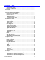
2 Introduction
HUS-SWP-32S IP Video Solution Overview
The core components of HUS-SWP-32S IP Video Solution are HUS-SWP-32S server and HUS-Client, which
can implement an effective and reliable IP video surveillance system with front-end security devices.
Figure 2-1 HUS-SWP-32S Architecture
HUS-SWP-32S Server(HUS-SWP-32S) – HUS-SWP-32S provides date management, video storage trigger,
and event and control , also provides streaming service, records, stores and playback videos applicable to
various types of video, intrusion and applicable to various types of video devices (video encoder, decoder, IP
camera, alarm panels….).
HUS-Client – Client of HUS XACT IP Video Solution supports live video display, playback from HUS-SWP32S, maps, alarms management and PTZ of IP front ends.
This user guide introduces the configuration and operation of HUS-SWP-32S .For instructions of HUS Client;
please refer to HUS-SWP-32S Client User Manual.
HUS-SWP-32S Overview
The HUS-SWP-32S service mainly includes these modules: NVR Service, Event Control Service, Video
Trigger Service, and Rules Engine Service.
HUS-SWP-32S Server – HUS-SWP-32S IP Video Solution adopts centralization management architecture
that all configuration data of HUS-SWP-32S IP Video Solution are stored in HUS-SWP-32S Server. All other
service of HUS-SWP-32S and client get configuration data from the Server other than store shared
information everywhere. HUS-SWP-32S Server provides functions such as the site map, user management,
device configuration, storage settings, information queries... It also provides a two-way user management
mode, one-stop interface management, and completes authority management.
Document Rev A – 07/15
4
HUS-SWP-32S User Manual
o Two-way user management mode: Allows the administrator to manage devices through role definition and
manage user authority allocation through role assignment.
o One platform management: Provides the user interface with unified style and configures the management
functions and parameters (such as site map, user department, and role distribution) in one platform.
o Multi-level authority management: Allows different users to access the system according to their
administration scopes and authorities after they log onto the system. The system performs strict identity
authentication to users and prohibits any illegal system incursion or operations exceeding a user’s authority.
Event Control Service – receives information about alarm, event, and state changes, sends operation
command and control information to front-end devices, is compatible with different communication methods
and formats, and caches the information locally. E&C service plays an important role of centralization control
management and alarm information management. HUS Client performs front-end device control by arbitrage
of E&C service.
Video Trigger Service– provides the video trigger service for digital video monitoring system and manages
video recording functions of multiple Streaming Services to ensure the reliability and stability of massive and
long-time video storage system.
Database Management Tool – maintains the database in HUS-SWP-32S Server, provides the functions of
database backup, recovery, stale-data clearance…. Implementing database optimization and advanced
management.
Document Rev A – 07/15
5
HUS-SWP-32S User Manual
3 Installation and Connection
For the installation and connection of HUS-SWP-32S, refer to the instructions of Document HUS-SWP-32S
Installation Guide provided in the package.
Document Rev A – 07/15
6
HUS-SWP-32S User Manual
4 Service Configurations and Initialization
This chapter describes the configuration of service components. The HUS-SWP-32S monitors and manages
the running status of service components with the Management Tool.
Each service in HUS-SWP-32S, should be configured in the Server should be assigned specifically in local
Management Tool.
The system supports the communication between HUS-SWP-32S Server and service components. Different
service components must be added into the corresponding HUS-SWP-32S Server in order to become a subdevice of HUS-SWP-32S Server. Thus, the Management Tool can start the service components and the
real-time communication and monitoring services of HUS-SWP-32S Server.
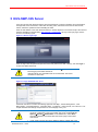
There is a shortcut to the Management Tool on the desktop. Double-click this shortcut to start the system.
Figure 4-1 the Shortcut of Management Tool
Because of the configuration order of the service components, user must
configure them according to the steps from this document; or abnormal
operation of the service components may result.
The Management Tool displays different component-configuration
interfaces according to which component user have installed. In the
following related interface pictures, all the service components are
installed on HUS-SWP-32S.
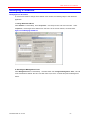
Configuring HUS-SWP-32S Server
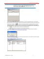
When launch the Management Tool for the first time, it prompts for the IP address of HUS-SWP-32S that
must be synchronized on the client. All the service components installed on HUS-SWP-32S must be
configured with synchronized the Server.
Figure 4-2 Management Tool Configuration
Document Rev A – 07/15
To connect the service components to the HUS-SWP-32S Server, you
must first configure the IP address of HUS-SWP-32S Server with the
Management Tool.
If user wants to change the default IP address 192.168.1.100, or modify
Server name, please refer to the chapter in document “HUS XACT032S
User Manual”.
7
HUS-SWP-32S User Manual
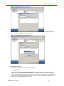
If the Management Tool does not prompt you to configure the server site
of HUS-SWP-32S Server, or you need to configure new site for HUSSWP-32S Server, select FileConfigure Management Sites, and the
same confirmation dialog box pops up.
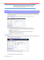
Figure 4-3 Configuring Management Sites
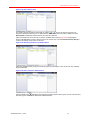
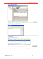
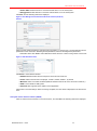
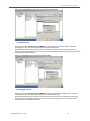
Select Configure Management Sites on the File menu to open the configuration page. In the “Configure
Management Sites” pane, fill in the IP address of the HUS-SWP-32S server that must be synchronized. After
inputting the IP address, click
, the system will search the existing HUS-SWP-32S Server according to
the inputted IP address. If HUS-SWP-32S Server runs normally on the computer with the corresponding
inputted IP address, the system then shows the information of the HUS-SWP-32S Server in the following list
box. Click
. You can delete the Server selected in the following list box.
Click Apply after finishing configuration to make the settings effective.
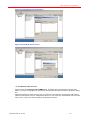
Click OK or Apply to save the settings, and wait until the system prompts successful completion.
Figure 4-4 Saving Management Site Information Successfully
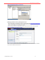
User can set HUS-SWP-32S Server on the client of the same computer, but the client on the same computer
can only synchronize with the Server.
Figure 4-5 Management Site – Synchronization
Document Rev A – 07/15
8
HUS-SWP-32S User Manual
Configuring Services
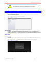
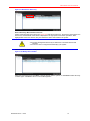
After user configured HUS-SWP-32S Server, open the main window of “Management Tool”, as shown in the
following screenshot.
Figure 4-6 the Main Window of “Management Tool”
In the preceding figure, the services in the list differ according to the installed
service components on computer. User can configure the services only if
they have added the corresponding device of the service component in HUSSWP-32S Server.
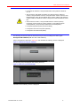
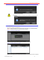
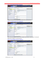
Event Control Service
Expand the tree items Management ToolServices, and double-click “HUS EC Service” under the
“Services” group.
Figure 4-7 Management Tool – Service
Click the “Configuration” tab in the open “HUS EC Service Properties” dialog box.
Document Rev A – 07/15
9
HUS-SWP-32S User Manual
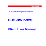
Figure 4-8 HUS EC Service Properties – Configuration
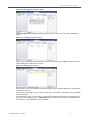
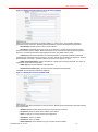
Select HUS-SWP-32S Server that user want to synchronize, and select the corresponding EC Service from
names in “EC Server List”, so as to connect the EC Service equipment with the central server deployed by
HUS-SWP-32S Server.
Click the “General” tab again, and start the EC Service.
Figure 4-9 HUS EC Service Properties – General
On the “General” page, click Start. When the service status turns to “Started”, the EC Service has started
successfully.
Figure 4-10 HUS EC Service Properties – General – Starting the Service
Document Rev A – 07/15
10
HUS-SWP-32S User Manual
HUS Trigger Service
Expand the tree items Management ToolServices, and double-click “HUS Trigger Service”. Click the
“Configuration” tab in the open “HUS Trigger Service Properties” dialog box.
Select HUS-SWP-32S Server that you want to synchronize, and select the corresponding HUS Trigger
Service names in “HUS Trigger Server List”, and then connect to the center server devices deployed by
HUS-SWP-32S Server.
Click the “General” tab again, and start the HUS Trigger Service.
Figure 4-11 HUS Trigger Service Properties
On the “General” page, click Start. When the server status turns to “Started”, the Video Server is started
successfully.
Rules Engine Service
Expand the tree items Management ToolServices, and double-click “HUS Rule Service”. Click the
“Configuration” tab in the open “HUS Rule Service Properties” window.
Select HUS-SWP-32S server that user want to synchronize, and select the corresponding Rules Engine
Service names in the “Rule Service” list, so as to connect the Rules Service with the center server devices
deployed by HUS-SWP-32S Server.
Click the “General” tab again, and start the Rules Engine Service.
Figure 4-12 HUS Rule Service Properties
Document Rev A – 07/15
11
HUS-SWP-32S User Manual
On the “General” page, click Start. When the server status turns to “Started”, the Rules Engine Service is
started successfully.
Time Synchronization Service
Time Synchronization service allows time synchronization between the server and client. Windows Time
service automatically synchronizes the system time with the network time to ensure the time on multiple
system devices is consistent. Windows Time service can serve as the time client that synchronizes with
other timeservers (time synchronization source), and can serve as the time synchronization source with
which Windows Time services on other computers synchronize.
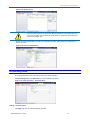
Double-click “Windows Time” under Management ToolServices, and then the “Windows Time Properties”
dialog box opens and the “General” page is displayed.
Figure 4-13 Windows Time Properties – Configuration
On the “General” page, click Start. When the service status turns to “Started”, the service is started
successfully.
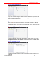
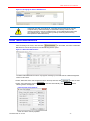
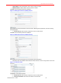
Click the “Configure” tab to configure the Windows Time service as the time client or time server.
Figure 4-14 Windows Time Properties – Configuration
Time client: Configure the Windows Time service to synchronize time with other timeservers.
1. Disabled: Disable the local computer to synchronize time with other time servers. For the server ,it
must be selected
2. Use domain hierarchy to find a time server: Synchronize time with a designated time server in domain.
3. Use specified server: Input the time server IP or server name.
4. Interval of time synchronization: Specify the interval (second) for automatic synchronization with time
server.
Time server: Configure the Windows Time service as a time server.
Document Rev A – 07/15
12
HUS-SWP-32S User Manual
1. Disable: Disable the Windows Time service on the local computer to serve as a time server.
2. Enable: Enable the Windows Time service on the local computer as a time server.
Note: for the server, it can’t be set both Time server and Time client.
Document Rev A – 07/15
13
HUS-SWP-32S User Manual
5 HUS-SWP-32S Server
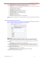
User can login the HUS-SWP-32S Server with Internet Explorer to perform operations and configurations,
manage sites, users and devices, make video recording rules, and search the records of alarm events,
videos, and device operations without installing the client.
Enter the site address of the HUS-SWP-32S Server in Internet Explorer in the format of http://<the server IP
address>/HUSsite (for default setting: http://192.168.1.100/HUSsite ), and go to the login page, which is
shown in the following figure.
Figure 5-1 Server Login Page
Enter the login name and password (the initial name and password are both “admin”), and click Login to
access HUS-SWP-32S Server.
Please set the server IP address in Control PanelNetwork Connections
before logging HUS-SWP-32S Server.
Internet Explorer 8.0 compatible mode is recommended. The lowest
resolution is 1280 x 800.
Figure 5-2 Login HUS-SWP-32S Server
HUS-SWP-32S Server contains the following eight tabs “Site Map”, “Device Management”, “User
Management”, “Role Management”, “Recording Rule”, “Log Report”, “Video Record”, and “Site Info”. This
chapter describes the settings and operations on each tab page one by one.
In Windows server system, user must modify IE security settings to see
the whole configuration page of HUS-SWP-32S Server. Select Internet
OptionsSecurityTrusted Sites on the Tools menu, select Sites,
and add the address of the HUS-SWP-32S Server page to the trusted
web sites list.
If user wants to change the server default IP address, please refer to the
Document Rev A – 07/15
14
HUS-SWP-32S User Manual
related chapter in this document
After login, the system automatically logs out if users do not make any
operations in a certain period. If users make operations on the page
again, the page returns to the login page.
Site Map
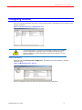
“Site Map” is used to create the tree of the local site. “Site Map” is divided into two parts, among which the
left part contains the “Local Sites” and “Parent Sites” list, and the right part displays the detailed information
of the currently selected site.
The following screenshot displays the site structure of a site, which contains only one site.
Figure 5-3 Site Structure
There are 5 device parameters for “Site Details”, which are described in the following list:
1. Site ID: The unique ID for each site, which is automatically generated by the system.
2. Site Name: the name of the site
3. Site IP: The IP address of the site, through which users can access the system.
4. Site Location: the physical address of the site
5. Description: the additional information of the site
Modifying Sites
In the “Local Sites” list, click the name of the local site, and then the right “Site Details” tab displays the name,
installation address and description of the site.
Figure 5-4 Modifying the Site Information
Fill in the information of the new site and click Save.
Document Rev A – 07/15
15
HUS-SWP-32S User Manual
The IP address of the current site is HUS-SWP-32S server’s IP address.
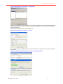
Device Management
“Device Management” is for the group management of specific devices according to its geographic
distribution or organization structure.
Click “Device Management” to show the following figure:
Figure 5-5 Device Structure
Device Navigation
The “Device Tree” displays the organization structure of all devices in system, and these devices are
classified by their types; and you can search the devices in the “Search” tab; “Device Discovery” is used for
searching, batch processing and batch adding devices to the system.
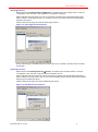
Adding a Device
Device Discovery
“Device Discovery” is used for searching devices in the LAN, batch processing and batch adding devices to
the system.
Select “Device Discovery” in “Device Management” tab, and the following window is displayed:
Figure 5-6 Discovery Condition
Select the device type and the service which you want to search in, and click OK.
Document Rev A – 07/15
16
HUS-SWP-32S User Manual
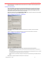
The device types of the current version are:
Honeywell HD-16DVR-D, Honeywell HVR-9000, Honeywell HD-16DVR-DV1.0.0
Axis IP Camera, HD 1080P IP Camera, HD 720P IP Camera, HD D1 IP
Camera, Honeywell 3M IP Camera, Honeywell ONVIF 720P IP Camera, HUS
NVR(HUS-NVR-1032), Pioneer ONVIF 3M IP Camera, VENTI 720P Series IP
Camera, VENTI D1 Series IP Camera, Honeywell 4-Channel Streamer HUSSE4V
ONVIF Generic Profile S, Honeywell HDZ Series IP Camera (ONVIF),
Honeywell Pioneer Series IP Camera (ONVIF), Honeywell Pancake IP
Camera(ONVIF), Honeywell Super HD Series IP Camera(ONVIF)
Honeywell Integrated System (Prowatch-HSDK)
Honeywell Access Control System (WPPCS)
Honeywell Access WIN-PAK (SEPE)
The following sections introduce the device discovery function according to the device types:
Honeywell HD-16DVR-D (With the case of HD-16DVR-D)
Select Honeywell HD-16DVR-D in Figure 5-6, and click OK. The following window is displayed:
Figure 5-7 Start Searching HD-16DVR-D
The following prompt is displayed after finishing discovery:
Figure 5-8 Discovery Finished Prompt
Click OK, and the following window is displayed:
Document Rev A – 07/15
17
HUS-SWP-32S User Manual
Figure 5-9 HUS-Device Discovery
Device Discovery Main Interface Overview
Search results are listed in the left pane in Figure 5-9 HUS-Device Discovery. Click device name listed in the
device tree, and the details of the device is displayed in the right pane for the further operations. BlueHighlight item means new device; Gray item means the device has existed in the system.
The system distinguishes devices by IP addresses. The existed devices will
be listed.
The “Device Link” is configured automatically by the system.
Click the details of devices to modify them as below:
Figure 5-10 Modify Device Details
Select the target devices and click Save to add the devices into the system; or click Back to select discovery
condition again. Click Exit to return to “Device Management”.
Document Rev A – 07/15
18
HUS-SWP-32S User Manual
The following Prompt is displayed after clicking Save:
Click Yes to save the settings.
If you select existed devices in the system and click Save, the following Warning is
displayed:
Click Yes to replace old devices.
Get Child Device
There are two methods to get child devices:
Method 1: Select the target device in the Device Discovery main interface and click Get Child Device
(Figure 5-9 HUS-Device Discovery. The following Prompt is displayed:
Figure 5-11 Discovery Finished Prompt
Click OK. Child devices will be listed in the device in the left pane tree as below:
Figure 5-12 Getting child devices finished
Method 2: Click the device name in the device tree in the left pane and the following interface is displayed:
Document Rev A – 07/15
19
HUS-SWP-32S User Manual
Figure 5-13 Get Child Device (Method 2)
Click Get Child Device (Figure 5-13) to get the child devices of the selected device. Child devices are
listed in the list below and in the device tree in the left pane:
Figure 5-14 Child Device List
The following warning may be displayed after clicking Get Child Device:
Click OK and look up the possible reasons. Repeat steps to try again.
Batch Process
HD-16DVR-D Batch Process
Select target devises in the Device Discovery main page. Right click and select “Batch Process” or click
HD-16DVR-D, the following window is displayed:
Document Rev A – 07/15
20
HUS-SWP-32S User Manual
Figure 5-15 Batch Process-HD-16DVR-D
Select the checkboxes before the parameters to be batch processed and set the parameters. Click OK to
save the settings or click Cancel to exit.
HD-16DVR-D Channel Batch Process
There are two methods to batch process HD-16DVR-D Channel:
Method 1: Select HD-16DVR-D Channel in the drop-down list as below:
Figure 5-16 Batch Process-Select HD-16DVR-D Channel
The following window is displayed:
Figure 5-17 Batch Process-HD-16DVR-D Channel
Select the checkboxes before the parameters to be batch processed and set the parameters. Click OK
save the settings or click Cancel to exit.
Method 2: Click the device to be batch processed in the device tree in the left pane, and the following
interface is displayed:
Document Rev A – 07/15
21
HUS-SWP-32S User Manual
Figure 5-18 Batch Process-Select HD-16DVR-D Channel
Select the channels to be batch processed. Right click and select “Batch Process” or click HD-16DVR-D
Channel. The following window is displayed:
Figure 5-19 Batch Process-HD-16DVR-D Channel
Select the checkboxes before the parameters to be batch processed and set the parameters. Click OK to
save the settings or click Cancel to exit.
HD-16DVR-D Stream Batch Process
There are two methods to batch process HD-16DVR-D Stream:
Method 1: Select HD-16DVR-D Stream in the drop-down list as below:
Figure 5-20 Batch Process-Select HD-16DVR-D Stream
The following window is displayed:
Document Rev A – 07/15
22
HUS-SWP-32S User Manual
Figure 5-21 Batch Process-HD-16DVR-D Stream
Select the checkboxes before the parameters to be batch processed and set the parameters. Click OK to
save the settings or click Cancel to exit.
Method 2: Click the device channel whose streams to be batch processed in the device tree in the left pane.
The following interface is displayed:
Figure 5-22 Batch Process-Select HD-16DVR-D Stream
Select the streams to be batch processed. Right click and select “Batch Process” or click HD-16DVR-D
Stream. The following window is displayed:
Figure 5-23 Batch Process-HD-16DVR-D Stream
Select the checkboxes before the parameters to be batch processed and set the parameters. Click OK to
save the settings or click Cancel to exit.
Filter
Filter function is used for filtering devices in the searching results.
Enter the “Device Name” in Figure 5-and click Filter to filter the devices.
Document Rev A – 07/15
23
HUS-SWP-32S User Manual
Or click the dropdown menu after Filter and click Advance Filter to set the advance filter conditions as
below:
Figure 5-24 Advance Filter
Click Filter to filter the devices.
Advanced Search
Advanced Search is used for filtering the discovery results and batch processing the filtered devices.
Click “Advance Search” tab in the left pane, the following interface is displayed:
Figure 5-25 Advance Search
Select HD-16DVR-D, HD-16DVR-D Channel or HD-16DVR-D Stream in the device type to list all the
corresponding devices. You can batch process them or do the further filter.
Adding Devices Manually
As shown in Figure 5- , you can add devices such as service, DVR, encoder, alarm device, access, matrix,
client, and so on. The steps of adding these devices are almost the same. This chapter provides a case of
adding HD-16DVR-D to describe the operations of adding devices.
Click “Digital Video Recorder” in the “Device Tree”, and the following tab page displays:
Figure 5-26 Creating a New Service
Click New, and the following tab page displays:
Document Rev A – 07/15
24
HUS-SWP-32S User Manual
Figure 5-27 Adding Information for the New Service
Select “HD-16DVR-D” in “Device Type”, set properties and device parameters for the new service, and click
Save. When the saving completes, the new device is displayed in the left “Device Tree”.
Devices or components can be added in batch by entering
batch number in “Batch Insert”. Any property can include
batch expression except the one will validation. Example: If
set batch number to 10 and set device type to 'Device{1}',
application will create 'Device1' to 'Device10'. But the
specifically parameters for each device or component will be
set or modified after being added.
Modifying Devices
In the “Device Tree”, click the device name you want to modify, and then the properties of the device are
shown in the right pane.
Figure 5-28 Device Information
The “Device Links” tab displays the devices of higher and lower level for connection of this device (for
example, the video encoder can be used for connection with the service to store or transmit the videos).
Figure 5-29 Device Connection
In the “Add” pane, select the device names, and click Add to connect the device with the service. By
selecting the connected devices and clicking Batch Delete you can break the connection between the
selected devices and services.
Document Rev A – 07/15
25
HUS-SWP-32S User Manual
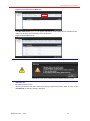
Deleting Devices
In the “Device Tree” select the devices you want to delete (see Figure 5-5), and click Delete on the bottom
of the “Device” pane. Then the following dialog box for confirmation pops up.
Figure 5-30 Deleting a Device
Click OK to delete the devices, or click Cancel to cancel the operation.
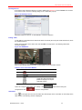
Editing “OSD”
To edit OSD for Honeywell Pioneer Enhanced Series IP Camera (Protocol) and HUSS-E4Vdevices, follow
the operations below:
Select the target device in the device tree and click Edit in the right pane. The following OSD Editor
window is displayed:
Figure 5-31 OSD Editor
Refer to the following table for the icons on the top right corner of the video window:
Table 5-1 Icons in the Video Window
Icon
Description
Remove
Pause/Play
/
/
/
Toggle the video rectangle size
(Minimum Display/Lock Aspect
Ratio/Full Screen)
Users can configure “OSD Editor” and “Library”. Click
configurations. Click
to quit without saving the
to save the configurations.
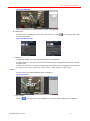
OSD Editor
Click
on the upper left corner and the follow the “Draw shapes here.” information to draw shape In the
video window. The following window is displayed:
Document Rev A – 07/15
26
HUS-SWP-32S User Manual
Figure 5-32 Add OSD
Select the target OSD and edit the following contents in the right pane:
OSD Content
Enter the texts to be displayed on the screen in the “Content”; or click
to insert dynamic texts:
the on the upper right comer
Figure 5-33Dynamic Text
OSD Style
Configure the location, font, color and other properties of the OSD texts;
If select “Auto fit size”, the size of the texts will scale with the video rectangle size and the tests will keep
the aspect ratio;
If select “Auto fit position.”, the margin of the texts will scale with the video rectangle size. It’s invalid when
the location is “left, center”, “center, top”, “center, center”, “center, bottom” or “right, center”.
Library
Click the “Library” tab and the following window is displayed:
Figure 5-34 Library
Save Template
Select the
Document Rev A – 07/15
on the right of the “Current Editing Item” to save the current editing item at a template:
27
HUS-SWP-32S User Manual
Figure 5-35 Save Template
Enter the template name and click OK. And the saved template is listed under the “Current Editing Item”:
Figure 5-36 Templates
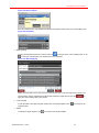
Batch Applying
To apply the template to devices in bathes, select the
on the right of the “Current Editing Item” or the
on the right of the template. The following window is displayed:
Figure 5-37 Batch Applying
Select the target device in the drop-down list of the “Device Type”. Enter the target device name in the
“Device Name” and the related devices will be listed. Select the target devices and click
apply the current editing OSD to the devices.
Load Template
To edit the OSD of the target template, double click the target template or click
target template.
to
on the right of the
Delete
To delete the target template, click
Document Rev A – 07/15
on the right of the target template.
28
HUS-SWP-32S User Manual
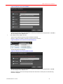
Users Management
User Management allows user to set username, password, and other information for a specific user, and
assign one or more roles to this user. Click User Management, to see the following screenshot.
Figure 5-38 User Management
Adding a User
Click New to open the “User Management” tab.
Figure 5-39 Adding a new User
Select “Common User” or “Mobile User” first, fills in the user’s information. The login name and password is
used to log in HUS-SWP-32S Server or client. The user level ranges from 0 to 255; the bigger the number,
the higher the control priority is (for example, when two users link to one video encoder’s cradle head at the
same time, the command of the user of high priority is sent to the cradle head). User name, login name and
department are supplemental options, which are defined by the customers themselves and do not affect the
operations of HUS-SWP-32S Server. By selecting one or more roles (for detailed steps of role management,
see Role Management ), you can grant the user corresponding authorities.
Figure 5-40 Filling in the New User’s Information
Document Rev A – 07/15
29
HUS-SWP-32S User Manual
Click Save. After the saving is complete, user can see the newly created username in the left user list, while
the new user’s general information and role information is shown on the right.
Note: * fields are mandatory to be fill in, while others are optional.
Figure 5-41 Success in Adding a New User
Modifying Users
In the user list, click the username user want to modify; the user’s information is will be displayed in the right
pane (see Figure 5- ).
On the “User Management” tab, user can modify properties such as username, login name, password, and
so on. Then click Save.
On the “Device Parameters” tab, user can see the user’s device and set the device parameter. If users enter
the DVR login username and password and click Save, the user can get the corresponding operation
authority of this DVR.
Figure 5-42 Modifying the User – Device Parameters
Deleting Users
To delete a single user, click the username you want to delete in the left user list, and then the user’s
information is displayed in the right pane. Click Delete, and a confirmation dialog box pops up as follows.
Figure 5-43 Deleting a User
Click OK to delete this user.
Document Rev A – 07/15
30
HUS-SWP-32S User Manual
To delete multiple users, select the users that user want to delete in the left user list, and then click Batch
Delete. A confirmation dialog box pops up as follows.
Figure 5-44 Deleting Multiple Users
Click OK to delete the selected users.
Role Management
Role Management allows user to grant proper authorities to different roles, so that user can choose the
needed authority conveniently when managing the users. Click Role Management to open the role
management page.
Figure 5-45 Role Management
Adding a Role
Click New as shown in Figure 5-45, and the page for adding new roles is displayed as follows.
Figure 5-46 Adding a Role
Enter the role name and role description.
Document Rev A – 07/15
31
HUS-SWP-32S User Manual
Figure 5-47 New Role Name and Description
Click Save. After saving is complete, a new role is added to the left user list, while the role’s properties are
shown in the right pane.
Figure 5-48 Success in Adding a New Role
User can set various authorities for the role on the tabs of “Web Authorization”, “Device View”, and
“Functions Authorization”. See Modifying Role .
Deleting Roles
To delete a single role, click the role you want to delete in the left role list, and click Delete in the right pane
displaying role information. A confirmation dialog box pops up as follows.
Figure 5-49 Deleting a Role
Click OK to delete the selected role.
To delete multiple roles, select multiple roles that you want to delete in the role list, and click Batch Delete
on the bottom left. A confirmation dialog box pops up as follows.
Document Rev A – 07/15
32
HUS-SWP-32S User Manual
Figure 5-50 Deleting Multiple Roles
Click OK to delete the selected roles.
Modifying Roles
In the role list, click the icon
to the left of the role name that you want to modify, and the role’s
properties are shown in the right pane.
Figure 5-51 Role Management Page
On the “Role Definition” tab, user can modify the role’s name and description. Then click Save.
On the “Web Authorization” tab, user can modify the operation authorities of the role in HUS-SWP-32S
Server, including site management, user management, role management, device view, device
management, recording rule, device event, device operation, recording, device type group, device type,
and so on. Each of these respectively corresponds to a sub-page of the Server:
Manage sites, manage users, manage roles, manage device view, manage devices, manage device type,
manage record rule, and report.
Figure 5-52 Web Authorization for Roles
Click or in front of the authority groups and user can expand or hide the specific authorities in the
group. By clicking
to the left of the authority-group name, user can select all the specific authorities in
the authority group. Click Save to save the modifications.
On the “Device View” tab, user can view and configure the specific devices available.
Document Rev A – 07/15
33
HUS-SWP-32S User Manual
Figure 5-53 Role’s Device View
The existing devices are listed in the middle; by clicking or in front of the device group user can
expand or collapse the device tree. To delete devices, select the devices user want to delete, and click
Batch Delete to delete the selected devices from the role’s authority.
Select and expand the root node “All” to view the available device groups (Figure 5-54 Assigning the
Device to Multiple Roles. Assign a device group to the current role, or click Create Root Device Group to
create a new device group for the current role.
Figure 5-54 Assigning the Device to Multiple Roles
Select the available device group (such as device group 2) and assign it to the current role. The following
figure is displayed:
Figure 5-55 Role’s Functions Authorization
Click the delete button
beside the device group to delete a specific device group, and the role that owns
this device group automatically deletes the related reference.
Document Rev A – 07/15
34
HUS-SWP-32S User Manual
Figure 5-56 Deleting Specific Device Group
Click Create Root Device Group to assign a new device group to the current role, which is displayed as
follows:
Figure 5-57 Creating Root Device Group
Input a name, device-group tag, and description for the new device group. Click Save, and the new device
group is displayed in the left device-group list.
Figure 5-58 Adding Device Group
Select a device group to be modified in the device-group list, and the right pane displays the corresponding
information of this group.
On the “Device Group” tab, user can modify the name, tag, and description of the device group. Click Save
to save the settings.
In the “Add Device” pane, user can click or to expand or collapse the device tree, select the device to
be added, or click the device group or name to reverse the selection of the sub-devices. Click Add to save
the modification, or click Reset to cancel the selection.
Document Rev A – 07/15
35
HUS-SWP-32S User Manual
Figure 5-59 Adding Device
User can add more than one group with different devices to a rule against the role’s
need. For example, user can add both “Video Devices” group and “the Fourth Floor”
group to the “Guide” role.
On the “Function Authorization” tab, user can configure the function authorization to a certain type of
devices for a role.
Figure 5-60 Function Authorization
Recording Rule
In the “Recording Rule” pane, user can set the rule for video recording.
Click Recording Rule on the Record menu, and the following tab opens.
Figure 5-61 Video Recording – Recording Rule
Adding a Recording Rule
Click Add, and user can see the following open tab.
Document Rev A – 07/15
36
HUS-SWP-32S User Manual
Figure 5-62 Creating New Recording Rule
Input the name and description of the new rule, select a trigger type, set the video’s duration and the rule’s
valid period after the video recording begins, and then click Save. You can see the newly added rule is
displayed in the left rule list, and you can continue to edit the rule’s properties such as recording device
(see the next chapter for detailed content).
Modifying a Recording Rule
Plan for Trigger
Click the icon
opens.
in front of the name of the rule that user want to modify, and the pane for editing rules
On the “Recording Rule” tab, user can modify the rule’s name, description, duration, and valid period. Then
click Save.
Figure 5-63 Modifying the Recording Rule (Schedule)
On the “Time Condition” tab, user can modify or delete the existing recording plan, add a new recording
plan, and enable or disable the recording rule. Click Edit or Delete to control a single recording plan; click
Enable All, Disable All, Cancel Edit, or Delete All to control all the recording rules; click Add to add new
recording rules.
Figure 5-64 Time Condition (Schedule)
On the “Record Device” tab, user can view and delete the existing devices, and add other devices to the
recording rule.
Document Rev A – 07/15
37
HUS-SWP-32S User Manual
Figure 5-65 Modifying the Recording Rule – Device Name (Schedule)
Alarm Trigger
Click the
icon in front of the name of the rule user want to modify, and the pane for editing rules opens.
On the “Recording Rule” tab, user can modify the rule’s name, description, duration, and valid period. Then
click Save.
Figure 5-66 Modifying the Recording Rule (Alarm)
On the “Time Condition” tab, user can modify or delete the existing recording plan, add a new recording
plan, and enable or disable the recording rule. Click Edit or Delete to control a single recording plan; click
Enable All, Disable All, Cancel Edit, or Delete All to control all the recording rules; click Add to add new
recording rules.
Figure 5-67 Time Condition (Alarm)
On the “Alarm Trigger Condition” tab, user can view or delete the existing alarm source and add other
alarm sources to the recording rule.
Document Rev A – 07/15
38
HUS-SWP-32S User Manual
Figure 5-68 Alarm Trigger Condition
On the “Record Device” tab, user can view or delete the existing devices and add other devices to the
recording rule.
Figure 5-69 Record Device (Alarm Trigger)
Deleting Recording Rule
In the pane for editing rules, click Delete, and a dialog box for confirmation opens.
Figure 5-70 Deleting Single Recording Rule
Click OK to delete this rule.
To delete multiple recording rules, select the rule that user want to delete in the recording rule list, and click
Batch Delete. Then the following dialog box opens for confirmation.
Document Rev A – 07/15
39
HUS-SWP-32S User Manual
Figure 5-71 Deleting Multiple Recording Rules
Click OK to delete the selected recording rule, or click Reverse Select to cancel the selection.
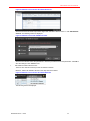
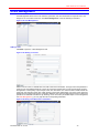
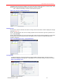
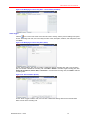
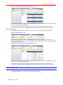
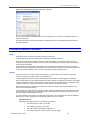
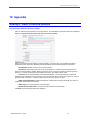
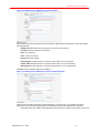
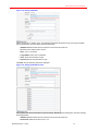
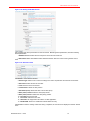
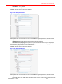
Log Report
You can search the device alarm events, device operations, user login, web operation, and you can also set
query conditions to get result quickly.
Device Alarm Log
Click Log Report, select “Device Alarm” to go to the query page of “Device Alarm”.
Figure 5-72 Device Alarm Log
Set proper query conditions, click View Report, and the records of alarm events that match the conditions
are displayed in the right pane. Expand an alarm event record, and you can see the detailed information of
the record.
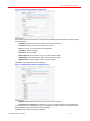
Figure 5-73 The Query Results of the Device Alarm Log
After finishing the search, you can locate the information of interest to users with the toolbar buttons, using
which you can also print the information.
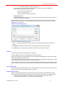
The system also supports exporting the query results to a target file. Select an output file format in
the ”Export” dropdown-list, and click Export to export all the information in this search to a target file.
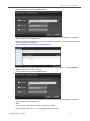
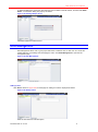
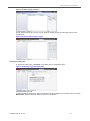
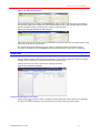
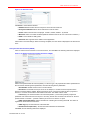
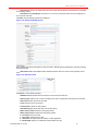
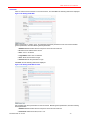
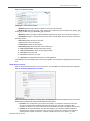
Device Operation Log
Click Log Report, select “Device Operation” to go to the query page of “Device Operation”.
Document Rev A – 07/15
40
HUS-SWP-32S User Manual
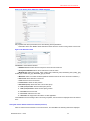
Figure 5-74 Device Operation Log
Set the corresponding query conditions, click View Report, and the device operation log that matches the
conditions is displayed in the right pane. The log contains “Device”, “User”, “Terminal”, “Result”, and
“Operation”.
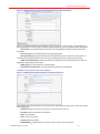
Figure 5-75 The Query Result of the Device Operation Log
After finishing the search, you can locate the information of interest to users with the toolbar buttons, using
which you can also print the information.
The system also supports exporting the query results to a target file. Select an output file format in
the ”Export” dropdown-list, and click Export to export all the information in this query to a target file.
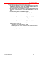
Figure 5-76 Different Output File Formats for Query
Excel has the maximum data limitation. There will be an error when output data is over
65536 rows. Reduce the search time and try again.
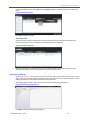
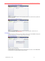
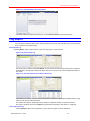
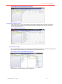
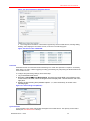
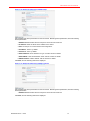
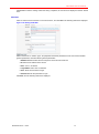
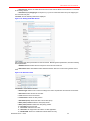
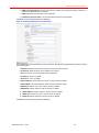
User Login Log
Click Log Report, select “User Login”, and you can go to the search page of “User Login”.
Figure 5-77 User Login Log
Set corresponding query conditions, click View Report, and the user login log that matches the conditions
is shown in the right pane. The log contains the login users, client type, Client IP, start data, and end date.
Document Rev A – 07/15
41
HUS-SWP-32S User Manual
Figure 5-78 The Query Results of the User Login Log
After finishing the search, you can locate the information of interest to users with the toolbar buttons, using
which you can also print the information.
The system also supports exporting the query results to a target file. Select an output file format in
the ”Export” dropdown-list, and click Export to export all the information in this search to a target file.
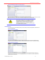
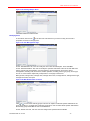
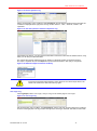
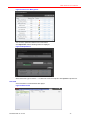
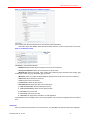
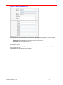
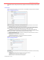
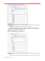
Web Operation Log
Click Log Report, select “Web Operation”, and you can go to the query page of “Web Operation”.
Figure 5-79 Web Operation Log
Set corresponding query conditions, click View Report, and the web operation log that matches the
conditions is shown in the right pane. The log contains the web information about the username, operation
time, operation and target…
Figure 5-80 The Query Results of the Web Operation Log
After finishing the search, you can locate the information of interest to users with the toolbar buttons, using
which you can also print the information.
The system also supports exporting the query results to a target file. Select an output file format in
the ”Export” dropdown-list, and click Export to export all the information in this search to a target file.
Video Record
Click Video Record, and you can go to the corresponding query page.
Document Rev A – 07/15
42
HUS-SWP-32S User Manual
Figure 5-81 Video Record Search
Set corresponding query conditions, click View Report, and the video records that match the conditions
are listed in the right pane, including the name of the Streaming Server, video recording device, the start
date and end date of video recording and the duration of video recording.
Figure 5-82 The Query Results of Video Record
After finishing the search, you can locate the information of interest to users with the toolbar buttons, using
which you can also print the information.
The system also supports exporting the query results to a target file. Select an output file format in
the ”Export” dropdown-list, and click Export to export all the information in this search to a target file.
Site Info
The local site information contains the system information of HUS-SWP-32S Server running on computer,
including version, information of the client, license limit, and device type.
Click the “Site Info” tab, which is shown in the following screenshot.
Figure 5-83 Local Site Information
The Current Information on the Client
Click the button
to the left of “Client” to expand and view all the login names, login time, IP addresses,
and other users’ basic information of the clients that are currently connected to the local site.
Document Rev A – 07/15
43
HUS-SWP-32S User Manual
Figure 5-84 The Current Information on the Client
The Number of System Licenses
Click “License Count”, and you can see the number of licenses supported by the system, including the
count of the currently connected devices and the license limit. Expand the tree, and you can see the
numbers of specific devices.
Figure 5-85 The License Count
Authorized Device Type
Click “Authorized Device Type”, and you can see the statistics for the types of connected devices supported
by the system. Expand the tree to see the description of the specific device type:
Figure 5-86 The Device Type Supported by System
Click “Resource” and the following window is displayed:
Document Rev A – 07/15
44
HUS-SWP-32S User Manual
Figure 5-87 Resource Management
You can view, update and delete icons in this window.
Click Upload File and the following window is displayed:
Figure 5-88 Upload File
Select “Resource Type” and click “…” to select icons from the computer. Click Upload to upload icons.
Download
Click “Download” to download HUS video player.
Figure 5-89 Download
Document Rev A – 07/15
45
HUS-SWP-32S User Manual
Logout
Click the Logout button
on the top-right corner of the window to logout from HUS-SWP-32S Server,
and returns to the system login page.
Document Rev A – 07/15
46
HUS-SWP-32S User Manual
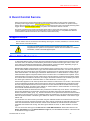
6 Event Control Service
Event Control Service receives device alarms and transmits the alarms to other system components
(including Video Trigger Service and Rules Engine Service) that receive the alarms. EC (Event Control)
Service also receives the control commands of the control devices from other components (including Video
Trigger Service and Rules Engine Service) in system, and controls the devices in unison.
The Event Control Service receives information about alarms, events and state changes, consequently
sending operation command and control information to front-end devices, it is compatible with different
communication methods and formats, and caches the information locally.
Support Device
The EC Service can be connected to the following device types: encoders, decoders, IP cameras, DVRs,
alarm devices, and matrix devices.
The types of specific devices supported and integrated functions differ, and
integrated into the system as new systems or devices become available. For detailed
information, consult a technical support expert.
Alarm Filter Mechanism
To distinguish different types of device data and avoid large amounts of repetitive device information being
sent to the client, the information transmitted by EC Service is divided into three types: alarm, status, and
event. Alarms are divided into blocked alarm, unblocked alarm, and timeout alarm. Depending on type of
device information, the EC Service transmits the information differently.
Blocked alarm applies to the frequently occurring alarms whose occurrence time is not of concern each time.
The EC Service filters the alarm device, type, and other detailed alarm information. For alarm information of
the same type and content sent by the same device, the EC Service only transmits the first alarm until the
client clears this alarm. The alarm type is defined as “Blocked Alarm” in “Alarm Attribute” of “Device Type”.
Unblocked alarm applies to important alarms whose occurrence time is considered to be important. For an
unblocked alarm of the same type and content sent by the same device, the EC Service sends the cached
and unclear alarm information to the client, according to the device information to be received by the client.
The alarm type is defined as “Unblocked Alarm” in “Alarm Attributes” of “Device Type”.
Timeout alarm applies to much more important alarms whose occurrence time is of concern. If the interval of
occurrence between two alarms (with the same device, alarm type, and detailed alarm information) is less
than the configured blocked timeout, then the alarm that occurs next time will be blocked instead of being
transmitted to the client. The alarm type is defined as “Timeout Alarm” in “Alarm Attributes” of “Device Type”,
and is set with the blocked timeout (unit: seconds).
The information about the device status is also processed in a blocked way on EC Service. The statuses of
devices are classified into several status categories and all status information that describes the same
feature constitutes a status group, e.g., device on line/off line; door open/closed. Please note that the status
information in the same status group is substituted while not simultaneous. The device status describes the
status of the device feature. The alarm type is defined as “Status” in “Alarm Attributes” of the “Device Type
Alarms” tab.
The information of a device event is processed using the unblocked method on the EC Service. When the
command control server receives information from device events, it transmits the information directly to the
client that subscribed the device information. Device event describes the normal interactive information
generated when devices are running. The alarm type is defined as “Event” in “Alarm Attribute” of “Device
Type”.
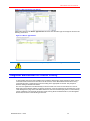
You can choose the alarm type in the Site Info tab in HUS-SWP-32S Server. Select alarm device in the
Device Type Name tree in the Authorized Device Type tab, and the detailed information of the device will
be showed on the right as below.
Document Rev A – 07/15
47
HUS-SWP-32S User Manual
Figure 6-1 Site Info-Device Type Alarms
Select alarm device in the Device Type Alarms tab and choose the alarm type on the right as shown in the
following screen shot.
Figure 6-2 Device Type Alarms
Choose the “Status Group” first if you define the alarm type as “Status”.
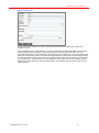
Judgment Mechanism for Control Priority
To deal conflict that occurs when multiple users control the same device at the same time, all the control
commands used for devices are first sent to the EC Service, which differentiates between all incoming
commands and then controls device control according to the appropriate command. The principle of
decision making is described as follows.
The user of a higher level can take authority for device control from a user of lower level, but a user of
lower level cannot take the authority for device control from a user of higher level or the same level. In the
“User Management” page of the HUS-SWP-32S Server, the user level and expiry date of control authority
can be configured. The user level ranges from 0-255, among which the lowest level is 0, and the highest
level is 255, as shown in the following screen shot.
Document Rev A – 07/15
48
HUS-SWP-32S User Manual
Figure 6-3 User Level
If a user gets control authority for a device, then the EC Service sets the release time of the control
authority in cache.
In the caching process of control authority, if a user of lower level or the same level asks for control of the
device, the device control authority remains unchanged, and the EC Service informs the user of the
usernames holding device control authority and the remaining time in authority. If the user of a higher level
asks control of the device, he/she can replace the original user and receive device control authority directly.
If a user who asks for device control is one who is already holding device control authority, the cache time
of control authority is extended to the next cycle. When the user’s cache time of control authority expires,
he/she loses control authority of the device automatically. This shifts the control authority to the next user
which requests it.
Document Rev A – 07/15
49
HUS-SWP-32S User Manual
7 HUS Trigger Service
The HUS Trigger Service is a server application that triggers video recording at a predefined time or when
an alarm occurs.
The HUS Trigger Service provides the video trigger service for digital video monitoring systems and
manages the video recording function of multiple Streaming Servers to ensure the reliability and stability of
large volume and long-term video storage systems.
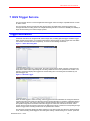
Trigger Mechanism
HUS-SWP-32S Server is configured with video storage rules, including planned trigger and alarm trigger.
When Trigger Service starts, it is configured with either a planned trigger or alarm trigger from HUS-SWP32S Server, and deals with them respectively, as shown in the following screenshot.
Figure 7-1 Video Recording Rule
At the preconfigured time for a video trigger, the Video Trigger Service sends a storage command to the
NVR service which takes responsibility for controlling related devices for the specified time duration. The
following screenshot displays the trigger time and the lasting time of recording that are defined by one
planned trigger rule.
Figure 7-2 Planned Trigger
When an alarm triggers a video recording, Video Trigger Service first subscribes the configured alarms or
events from Event Control Service. When EC Service receives the alarm, it sends the subscribed alarm to
Video Trigger Service, and Video Trigger Service decides whether video storage is needed according to
the specific configuration information of the alarm trigger rule. When the video must be stored, Video
Trigger Service sends the storage command to the NVR service which controls the corresponding storage
device to trigger video recording of alarms for the specified time duration.
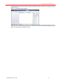
The following screenshot displays the alarm settings for one alarm trigger rule. When the selected alarms
occur, video recording will be triggered. The lasting time setting of the recording is 10 minutes. (Note that
Document Rev A – 07/15
50
HUS-SWP-32S User Manual
the first channel of alarm input and alarm restore is unselected, so the two alarms do not trigger recording
when they occur.)
Figure 7-3 The Rule of Alarm Trigger
When the Video Trigger Service is running, if user add, modify or delete one video recording rule in HUSSWP-32S Server, the Video Trigger Service can update the information automatically and dynamically, and
adjust the corresponding recording rule in time.
Document Rev A – 07/15
51
HUS-SWP-32S User Manual
8 Database Management Tool
The Database Management Tool is used to maintain the database of HUS-SWP-32S Server, providing the
functions of database backup, restore, cleanup of old data, and so on, in order to optimize and manage the
database.
The major functions of the Database Management Tool are backing up of the database, restoring the
database, and cleaning up the database.
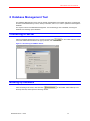
Connecting to Server
Start the Database Management Tool, and then click the button
on the toolbar. Select a server
name and authentication method in the pop-up window, and click Connect.
Figure 9-1 Connecting to DataBase Server
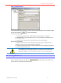
Backing up Database
After connecting to the server, click the button
the drop-down list, which opens the following window.
Document Rev A – 07/15
on the toolbar, select “Backup” from
52
HUS-SWP-32S User Manual
Figure 9-2 Database Backup
Choose the database name, backup type, and the path for saving the backup file in the preceding window,
and then click the button
to backup the database.
Instructions for backup type:
1. Complete backup: Back up the whole database, including all data in the database.
2. Differential Backup: Back up the data that is in the current database but different from the
last complete backup.
3. Transaction Log: Only back up the transaction logs in the current database.
Instructions for other options:
1. Attach to the backup files: if the backup file already exists, add the backup data to the
original file. If there is no backup file, create a new backup file.
2. Overwrite the backup file: if the backup file already exists, the new backup file will replace it;
if not, this file becomes the new one.
The database name in this system is “HusAdv”. Be sure to choose the right database
when backing up or restoring the database. Use the default name “HusAdv” when
backing up database, so as to avoid operation failure when restoring the database.
Restoring Database
After connecting to the server, click the button
the drop-down list, and the following window opens.
Document Rev A – 07/15
on the toolbar, select “Restore” from
53
HUS-SWP-32S User Manual
Figure 9-3 Restoring Database
Choose the database to be restored or enter a new database name, and then click the button
a backup file in the pop-up window as follows
to add
Figure 9-4 Specifying a Backup File
Add one or more backup files, and click OK. On the “Backup Set” page, you can see the backup sets in the
current backup file.
Figure 9-5 Selecting Backup Sets
Select the backup set to be restored in the “Backup Set” list, and then click the button
restore it.
User can select another path for saving the database file in the “Option” page as follows.
Document Rev A – 07/15
54
to
HUS-SWP-32S User Manual
Figure 9-6 Changing the Path of Database File
If there are more than one backup set , especially when the backup set includes
complete backup, differential backup, and transaction backup, make sure the
restoring sequence is: the last complete backup some differential backups after
the complete backup the transaction log backup and ending transaction log
backup after the differential backup.
Data Table Maintenance
After connecting to the server, click the button
on the toolbar, then select “DataTable
Maintenance” from the drop-down list, and the following window opens.
Figure 9-7 Data Table Maintenance
The Data Table Maintenance function only supports cleaning up of the SQL Server of Data Management
Center on this server.
Select “Data Clear Time” and configure the time in the drop-down list, click
Select “Auto Clear Data” and click
following window is displayed:
to clear the data.
to clear data automatically. Click
and the
Figure 8-8 Auto Clear Settings
Users can set the custom properties.
Document Rev A – 07/15
55
HUS-SWP-32S User Manual
Click
to clear the logs before the time point.
Notes: Maintenance Plan is unavailable on HUS-SWP-32S series production.
Before clearing the data, make sure you have backed up the data, as the data cannot
be restored after the cleanup.
Document Rev A – 07/15
56
HUS-SWP-32S User Manual
9 Configuring HUS NVR Services
This chapter describes how to configure HUS-NVR Service in Management Tool.
HUS-SWP-32S IP Security Integration Platform includes HUS-NVR Service. Management
Tool can start its service and the real-time communication and monitoring services of HUS-SWP-32S
Server.
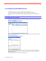
Configuring NVR Service
In the main window of “Management Tool”, as shown in the following screenshot, expand the tree items
Management ToolServices in the left pane.
Figure 10-1 Management Tool – Services
Double click “HUS Network Video Recorder”. Click the “Configuration” tab in the open “HUS Streaming
Server Properties” dialog box.
Figure 10-2 HUS NVR Properties – Properties
Select HUS-SWP-32S Server that you want to synchronize, and select the corresponding HUS NVR
Service names in the HUS NVR list, so as to connect the HUS-NVR Service with the HUS-SWP-32S
deployed by the Server.
Click the “General” tab again, and start the HUS-NVR Service.
Document Rev A – 07/15
57
HUS-SWP-32S User Manual
Figure 10-3 HUS Streaming Server Properties – General
On the “General” page, click Start. When the service status turns to “Started”, the Streaming Service is
started successfully.
The state information and monitoring interface of Streaming Service is automatically displayed after it is
started successfully.
HUS NVR Service Function
Relay
HUS-NVR Service can relay the real-time streaming to the client.
A typical application process of relaying the streaming is described as follows:
Firstly, HUS Client sends a request command to HUS-NVR Service for a real-time streaming. After it
receives and analyzes this command, it connects the corresponding front-end device links, and requests
for the real-time streaming.
If the preceding two steps perform successfully, then the streaming link between HUS Client and HUSNVR Service and the link between HUS-NVR Service and the front-end device are connected, which forms
a one-way real-time streaming circle. Thus, the transmitting function is implemented.
Storage
HUS-NVR Service can store the real-time streaming for a certain period of time when it receives the
storage command from Trigger Service of HUS-SWP-32S.
A typical application process of storage is described as follows (take “schedule trigger” as example):
Firstly, Trigger Service of HUS-SWP-32S gets the “trigger schedule” configured in the Server. If the trigger
condition is satisfied, Trigger Service sends a request command to HUS-NVR Service, indicating that the
real-time streaming of a certain channel will be stored within the specified time period.
When HUS-NVR Service receives and analyzes the command, it links to the corresponding front-end
device for the real-time streaming.
If the preceding two steps work successfully, then the streaming link between HUS-NVR Service and the
front-end device is connected, and HUS-NVR Service starts storing the streaming into the disk and will
stop the storage until the specified end time.
In practical situation, large amounts of video files are generated, and maintaining the video file database
becomes one of the most important works after the system is put into operation.
Disk Maintenance
Maintainers should pay attention to the following parameters:
1.
The total capacity of disk: C (unit: GB)
2.
The remaining capacity: R (unit: GB)
3.
The total number of device links supported : N
4.
The maximum bit rate of each channel: rate (unit: Mbps)
Document Rev A – 07/15
58
HUS-SWP-32S User Manual
5.
The number of days for storage: D (unit: day)
The calculation of disk storage space must meet this condition: the remaining available disk
space>the required space for storing video files
(C*1024-512)>D*3600*24*N*rate/8
That is C>10.55D*N*rate+0.5
512 (MB) refers to the reserved disk space.
Index Recovery Tool
IndexMaker(SQLite) is a recovery tool for video index files provided by HUS-NVR Service, which you
can find it in the installation directory.
When HUS-NVR Service shuts down abnormally (caused by abnormal program or power-off), damage
might be caused to index files. So before restarting HUS-NVR Service, you must recover the index files,
otherwise it may cause error.
Figure 10-4 Index Recovery Tool
To recover the index files, follow these steps:
1. Click “…” and specify the DB path (the path where the index files generated by the HUS-NVR are
saved).
2. Click Add and specify the storage path (the corresponding disk list; refer to the disk list).
3. Click Start. Once it is complete, the index files will have been successfully recovered.
Playback
HUS-NVR Service supports video playback in HUS Client.
A typical application process of video playback is described as follows.
Firstly, HUS Client sends a request command to HUS-NVR Service designating for a certain history video
with the specified start time and end time.
After HUS-NVR Service receives and analyzes the command, it finds the file list that matches the condition
in local video database, and locates the correct start and end time.
If the preceding two steps work successfully, then the streaming link between HUS-NVR Service and HUS
Client is connected, and HUS-NVR Service begins to distribute the history streaming to HUS Client to play
it.
Downloading Videos
This function is similar to the playback function. The only difference is that the history streaming will not be
played but storing it in the local hard disk of the HUS Client.
Dynamic Synchronization
When the settings of Streaming Service (HUS-NVR Service) are changed in the Management Service,
HUS-NVR Service automatically synchronizes with it and applies the new settings. The settings include:
1. The configuration information of Streaming Service, including device name, tag, location,
description, device parameter, etc., as shown in the following figure.
Document Rev A – 07/15
59
HUS-SWP-32S User Manual
Figure 10-5 The Parameters of Streaming Service
2. The configuration information of device links supported by the HUS-NVR Service, including adding,
deleting, and modifying the information of a link, as shown in the following figure.
Figure 10-6 Device Links of HUS-NVR
Prerecord
HUS-NVR Service can cache the real-time streaming for a certain time (less than or equals to 10 minutes).
When there is an event or alarm triggering recording, prerecording may help tracing the situation before the
event or alarm occurs.
To configure the prerecording settings, follow these steps:
1. Log in HUS-SWP-32S Server.
2. Navigate to DeviceDevice Management, and select the target NVR in the left device tree.
In the “Device Links” tab, select the target link and it displays the “Link Parameters” tab in the
right pane.
3. Specify the prerecording time (available options: 1, 5, and 10 minutes), as shown in the
following figure:
Figure 10-7 Prerecording Time (Minutes)
Cycle Overwrite
Cycle overwrite is one of the video storage strategies of HUS-NVR Service. The capacity of each disk is
limited (see “Disk Maintenance” section).
Document Rev A – 07/15
60
HUS-SWP-32S User Manual
HUS-NVR Service supports the cycle overwrites in the following two situations:
Delete the videos older than N days regularly. If the disk can store the videos for N days,
HUS-NVR Service will delete the video files older than N days regularly according to the
required video storage space after a certain capacity is filled.
Delete the oldest videos when the disk capacity is full, and the related parameters can be
specified in the “streamingserver.xml” file (it is in the installation directory of HUS-NVR
Service):
The default maximum capacity of each file block is 200MB.
It can be configured by “<PREF NAME="storage_video_chip_size"
TYPE="UInt32" >200</PREF>” in the “streamingserver.xml” file.
When the remaining space of the disk is less than 1GB (default), you cannot create new
files on the disk.
It can be configured by “<PREF NAME="storage_disk_create_empty_remain"
TYPE="UInt32" >1024</PREF>” in the “streamingserver.xml” file;
When the remaining space of the disk is less than 512MB (default), data cannot be written
to the disk.
It can be configured by “<PREF NAME="storage_disk_write_empty_remain"
TYPE="UInt32" >512</PREF>” in the “streamingserver.xml” file.
When the remaining space of disk is less than 2GB (default), HUS-NVR Service starts to
search the oldest videos. When more than 1GB (default) of videos is searched, it stops
searching and delete all these videos.
The remaining space can be configured by “<PREF
NAME="storage_cycle_overwirte_remain_size" TYPE="UInt32" >2048</PREF>” in
the “treamingserver.xml” file.
The file size of searched videos can be configure by “<PREF
NAME="storage_cycle_overwirte_size" TYPE="UInt32" >1024</PREF>” in the
“streamingserver.xml” file.
Document Rev A – 07/15
61
HUS-SWP-32S User Manual
10 Appendix
Adding IP Video Front End Devices
Honeywell Super HD Series IP Camera (ONVIF)
Click “IP Video Front End Devices” in the “Device Tree”, and click New. The following interface is displayed:
Figure 0-1 Adding Honeywell Super HD Series IP Camera (ONVIF)
Select “Honeywell Super HD Series IP Camera (ONVIF)” in “Device Type”, set properties and device
parameters for the new device. Besides general parameters, there are following device parameters:
1. EventEnable: Enable event function to receive alarms.
2. EventPort: The Socket service port in EC for the Adaptor, to receive the event reports from the
devices connected with the adaptor. Make sure this port in EC cannot be occupied by other programs or
devices, or it cannot receive alarms and ON/OFF line status. The default value is 6150.
3. Timeout (s): The interval between two heart beat packets. (10 seconds by default.) Adjust this
parameter if the network environment is poor or too many devices are connected. The formula is: Timeout
period=number of cameras× (number of alarms per second of a camera×2+1)/20.
4. PING Timeout(50-400ms): Set the interval time of sending and receiving the PING. The device is
regarded as disconnected if it is timeout.
5. PING Try(1-3): Set the trial times of the PING test.
6. Heartbeat Interval(60-180s): Set the interval time between two heartbeats.
Click Next, and the following interface is displayed:
Document Rev A – 07/15
62
HUS-SWP-32S User Manual
Figure 0-2 Adding Super HD Series (ONVIF) DVR
Set properties and device parameters for the new device. Besides general parameters, there are following
device parameters:
1. HUS EC Service: Select Service Component- Event & Control Service.
2. IP Address: Enter the Enter the IP Address of the device.
3. Port: Set the port for communication and configuration.
4. UserName: “admin” by default.
5. Password: “1234” by default.
6. AuthenAddress: HTTP Address to log on. Ask the vendor for details.
7. AuthenMode: HTTP authentication mode. Ask the vendor for details.
8. ONVIF Address: ONVIF address. Ask the vendor for details.
Click Next, and the following interface is displayed:
Figure 0-3 Adding Super HD Series (ONVIF) Channel
1. HUS EC Service: Select Service Component- Event & Control Service.
2. PTZ Pace X (1-9) mapping to: PTZ pace X (1-9) can be customized. Each PTZ pace mappings to
one front-end PTZ pace. For Example, PTZ Pace 9 mappings to PTZ85; PTZ Pace 1 mappings to PTZ5.
Customized PTZ pace provides more accurate positioning.
Click Next, and the following interface is displayed:
Document Rev A – 07/15
63
HUS-SWP-32S User Manual
Figure 0-68 Adding Super HD Series (ONVIF) Streamer
Set properties and device parameters, there are following device parameters:
1. Alternative View: Click Find to select alternative stream when the current running stream cannot work:
Figure 0-69 Alternative View
Click Reset to clear selected streams.
2. HUS EC Service: Select Service Component- Event & Control Service.
3. Honeywell HUS-NVR: Select which HUS-NVR to store the video.
4. MediaProfile: Select from quality_h264, mobile_h264, balanced_h264, bandwidth_h264, quality_jpeg,
mobile_jpeg or balanced_jpeg. Bandwidth_jpeg by default.
5. Multicast: Select it to enable multicast (Multicast address must be set on the device IE in advance.).
6. Show Text: Select this item to show text.
7. Text: Enter the text to be showed.
8. Text Position: Select the text position.
9. ShowDate (Time): Select this item to show date (time).
10. Date (Time) Format: Select the date (time) format.
11. Date (Time) Position: Select the date (time) position.
12. Font Size: Set the font size.
13. Font Color: Select the font color.
14. Switch ID: Not supported in this edition of HUS application.
Click Finish to save the settings. When the saving completes, the new device is displayed in the left “Device
Tree”.
Honeywell Pioneer Enhanced Series IP Camera (Protocol)
Click “IP Video Front End Devices” in the “Device Tree”, and click New. The following interface is displayed:
Document Rev A – 07/15
64
HUS-SWP-32S User Manual
Figure 0-4 Adding Honeywell Pioneer Enhanced Series IP Camera (Protocol)
Select “Honeywell Pioneer Enhanced Series IP Camera (Protocol)” in “Device Type”. Set properties and
device parameters for the new device. Besides general parameters, there are following device parameters:
1. Event Port: From the listed EC services, the user should appoint a specific one to receive alarm
information.
2. Event Timeout: The interval between two heart beat packets.
3. Event Resubscribe: Enable this item will resubscribe alarm when the device is reconnected. It is
recommended to enable this item for the first using. And disable it when the system has run stably.
4. PING Timeout(50-400ms): Set the interval time of sending and receiving the PING. The device is
regarded as disconnected if it is timeout.
5. PING Try(1-3): Set the trial times of the PING test.
6. Heartbeat Interval(60-180s): Set the interval time between two heartbeats.
Click Next, and the following interface is displayed:
Figure 0-5 Adding Pioneer Enhanced Series IP Camera (Protocol)
Set properties and device parameters for the new device. Besides general parameters, there are following
device parameters:
1. HUS EC Service: Select Service Component- Event & Control Service.
2. IP Addr: Enter the IP address of the device.
3. Port: “80” as default.
4. User: “admin” by default.
5. Password: Null by default.
6. EnableMotion:Enable this item to send the motion alarm to the HUS system.
Document Rev A – 07/15
65
HUS-SWP-32S User Manual
7. Enable DIDO: Enable this item to send the external alarm–in to the HUS system.
8. DITriggerICR: Enable this item to send the external alarm–out to the HUS system.
Click Next, and the following interface is displayed:
Figure 0-127 Adding Pioneer Enhanced Series IP Camera (Protocol)
Stream
Select “Pioneer Enhanced Series IP Camera (Protocol) Stream” in “Device Type”, set properties and device
parameters for the new device. Besides general parameters, there are following device parameters:
1. Alternative View: Click Find to select alternative stream when the current running stream cannot work :
Figure 0-128 Alternative View
Click Reset to clear selected streams.
2. HUS EC Service: Select Service Component- Event & Control Service.
3. Profile: Select which stream to be played. Profile1, Profile2, Profile3…by default.
4. Multicast: Select it to enable multicast (Multicast address must be set on the device IE in advance.).
5. OSD: For the details of editing OSD.
6. Switch ID: Not supported in this edition of HUS application
Click Finish to save the settings. When the saving completes, the new device is displayed in the left “Device
Tree”.
Honeywell Pioneer Series IP Camera (ONVIF)
Click “IP Video Front End Devices” in the “Device Tree”, and click New. The following interface is displayed:
Document Rev A – 07/15
66
HUS-SWP-32S User Manual
Figure 0-6 Adding Honeywell Pioneer Series IP Camera (ONVIF)
Select “Honeywell Pioneer Series IP Camera (ONVIF)” in “Device Type”, set properties and device
parameters for the new device. Besides general parameters, there are following device parameters:
1. EventEnable: Enable event function to receive alarms.
2. EventPort: The Socket service port in EC for the Adaptor, to receive the event reports from the
devices connected with the adaptor. Make sure this port in EC cannot be occupied by other programs or
devices, or it cannot receive alarms and ON/OFF line status. The default value is 6150.
3. Timeout (s): The interval between two heart beat packets. (10 seconds by default.) Adjust this
parameter if the network environment is poor or too many devices are connected. The formula is: Timeout
period=number of cameras× (number of alarms per second of a camera×2+1)/20.
4. PING Timeout(50-400ms): Set the interval time of sending and receiving the PING. The device is
regarded as disconnected if it is timeout.
5. PING Try(1-3): Set the trial times of the PING test.
6. Heartbeat Interval(60-180s): Set the interval time between two heartbeats.
Click Next, and the following interface is displayed:
Figure 0-7 Adding Pioneer Series (ONVIF) DVR
Set properties and device parameters for the new device. Besides general parameters, there are following
device parameters:
1. HUS EC Service: Select Service Component- Event & Control Service.
2. IP Address: Enter the Enter the IP Address of the device.
3. Port: Set the port for communication and configuration.
4. UserName: “admin” by default.
5. Password: “1234” by default.
6. AuthenAddress: HTTP Address to log on. Ask the vendor for details.
Document Rev A – 07/15
67
HUS-SWP-32S User Manual
7. AuthenMode: HTTP authentication mode. Ask the vendor for details.
8. ONVIF Address: ONVIF address. Ask the vendor for details.
Click Next, and the following interface is displayed:
Figure 0-8 Adding Pioneer Series (ONVIF) Channel
Set properties and device parameters for the new device. Besides general parameters, there are following
device parameters:
1.
HUS EC Service: Select Service Component- Event & Control Service.
Click Next, and the following interface is displayed:
Figure 0-9 Adding Pioneer Series (ONVIF) Streamer
Set properties and device parameters, there are following device parameters:
1. Alternative View: Click Find to select alternative stream when the current running stream cannot work:
Figure 0-10 Alternative View
Click Reset to clear selected streams.
2.
HUS EC Service: Select Service Component- Event & Control Service.
3. Honeywell HUS-NVR: Select which HUS-NVR to store the video.
Document Rev A – 07/15
68
HUS-SWP-32S User Manual
4. MediaProfile: Select from quality_h264, mobile_h264, balanced_h264, bandwidth_h264,
quality_jpeg, mobile_jpeg or balanced_jpeg. Bandwidth_jpeg by default.
5.
Multicast: Select it to enable multicast (Multicast address must be set on the device IE in advance.).
6.
Show Text: Select this item to show text.
7.
Text: Enter the text to be showed.
8.
Text Position: Select the text position.
9.
ShowDate (Time): Select this item to show date (time).
10. Date (Time) Format: Select the date (time) format.
11. Date (Time) Position: Select the date (time) position.
12. Font Size: Set the font size.
13. Font Color: Select the font color.
14. Switch ID: Not supported in this edition of HUS application.
Click Finish to save the settings. When the saving completes, the new device is displayed in the left “Device
Tree”.
Honeywell Pioneer 3M Fisheye Series IP Camera
Click “IP Video Front End Devices” in the “Device Tree”, and click New. The following interface is displayed:
Figure 0-11 Adding Honeywell Pioneer 3M Fisheye Series IP Camera
Select “Honeywell Pioneer 3M Fisheye Series IP Camera” in “Device Type”. Set properties and device
parameters for the new device. Besides general parameters, there are following device parameters:
1. Event Port: From the listed EC services, the user should appoint a specific one to receive alarm
information.
2. Event Timeout: The interval between two heart beat packets.
3. Event Resubscribe: Enable this item will resubscribe alarm when the device is reconnected. It is
recommended to enable this item for the first using. And disable it when the system has run stably.
4. PING Timeout(50-400ms): Set the interval time of sending and receiving the PING. The device is
regarded as disconnected if it is timeout.
5. PING Try(1-3): Set the trial times of the PING test.
6. Heartbeat Interval(60-180s): Set the interval time between two heartbeats.
Click Next, and the following interface is displayed:
Document Rev A – 07/15
69
HUS-SWP-32S User Manual
Figure 0-12 Adding Pioneer 3M Fisheye Series IP Camera
Set properties and device parameters for the new device. Besides general parameters, there are following
device parameters:
1. HUS EC Service: Select Service Component- Event & Control Service.
2. IP Addr: Enter the IP address of the device.
3. Port: “80” as default.
4. User: “admin” by default.
5. Password: Null by default.
6. EnableMotion:Enable this item to send the motion alarm to the HUS system.
7. Enable DIDO: Enable this item to send the external alarm–in to the HUS system.
8. DITriggerICR: Enable this item to send the external alarm–out to the HUS system.
Click Next, and the following interface is displayed:
Figure 0-13 Adding Pioneer 3M Fisheye Series IP Camera Streamer
Select “Pioneer 3M Fisheye Series IP Camera Streamer” in “Device Type”, set properties and device
parameters for the new device. Besides general parameters, there are following device parameters:
1. Alternative View: Click Find to select alternative stream when the current running stream cannot work :
Document Rev A – 07/15
70
HUS-SWP-32S User Manual
Figure 0-14 Alternative View
Click Reset to clear selected streams.
2. HUS EC Service: Select Service Component- Event & Control Service.
3. Honeywell HUS-NVR: Select which HUS-NVR to store the video.
4. Profile: Select which stream to be played. Profile1, Profile2, Profile3…by default.
5. Multicast: Select it to enable multicast (Multicast address must be set on the device IE in advance.).
6. OSD: For the details of editing OSD.
7. Switch ID: Not supported in this edition of HUS application
Click Finish to save the settings. When the saving completes, the new device is displayed in the left “Device
Tree”.
Honeywell Pancake IP Camera (ONVIF)
Click “IP Video Front End Devices” in the “Device Tree”, and click New. The following interface is displayed:
Figure 0-15 Adding Honeywell Pancake IP Camera (ONVIF)
Select “Honeywell Pancake IP Camera (ONVIF)” in “Device Type”, set properties and device parameters for
the new device. Besides general parameters, there are following device parameters:
1. EventEnable: Enable event function to receive alarms.
2. EventPort: The Socket service port in EC for the Adaptor, to receive the event reports from the
devices connected with the adaptor. Make sure this port in EC cannot be occupied by other programs or
devices, or it cannot receive alarms and ON/OFF line status. The default value is 6150.
3. Timeout (s): The interval between two heart beat packets. (10 seconds by default.) Adjust this
parameter if the network environment is poor or too many devices are connected. The formula is: Timeout
period=number of cameras× (number of alarms per second of a camera×2+1)/20.
4. PING Timeout(50-400ms): Set the interval time of sending and receiving the PING. The device is
regarded as disconnected if it is timeout.
5. PING Try(1-3): Set the trial times of the PING test.
6. Heartbeat Interval(60-180s): Set the interval time between two heartbeats.
Click Next, and the following interface is displayed:
Document Rev A – 07/15
71
HUS-SWP-32S User Manual
Figure 0-16 Adding Pancake Series (ONVIF) DVR
Set properties and device parameters for the new device. Besides general parameters, there are following
device parameters:
1. HUS EC Service: Select Service Component- Event & Control Service.
2. IP Address: Enter the Enter the IP Address of the device.
3. Port: Set the port for communication and configuration.
4. UserName: “admin” by default.
5. Password: “1234” by default.
6. AuthenAddress: HTTP Address to log on. Ask the vendor for details.
7. AuthenMode: HTTP authentication mode. Ask the vendor for details.
8. ONVIF Address: ONVIF address. Ask the vendor for details.
Click Next, and the following interface is displayed:
Figure 0-17 Adding Pancake Series (ONVIF) Channel
Set properties and device parameters for the new device. Besides general parameters, there are following
device parameters:
1. HUS EC Service: Select Service Component- Event & Control Service.
Click Next, and the following interface is displayed:
Document Rev A – 07/15
72
HUS-SWP-32S User Manual
Figure 0-18 Adding Pancake Series (ONVIF) Streamer
Set properties and device parameters, there are following device parameters:
1. Alternative View: Click Find to select alternative stream when the current running stream cannot work:
Figure 0-19 Alternative View
Click Reset to clear selected streams.
2. HUS EC Service: Select Service Component- Event & Control Service.
3. Honeywell HUS-NVR: Select which HUS-NVR to store the video.
4. MediaProfile: Select from quality_h264, mobile_h264, balanced_h264, bandwidth_h264, quality_jpeg,
mobile_jpeg or balanced_jpeg. Bandwidth_jpeg by default.
5. Multicast: Select it to enable multicast (Multicast address must be set on the device IE in advance.).
6. Show Text: Select this item to show text.
7. Text: Enter the text to be showed.
8. Text Position: Select the text position.
9. ShowDate (Time): Select this item to show date (time).
10. Date (Time) Format: Select the date (time) format.
11. Date (Time) Position: Select the date (time) position.
12. Font Size: Set the font size.
13. Font Color: Select the font color.
14. Switch ID: Not supported in this edition of HUS application.
Click Finish to save the settings. When the saving completes, the new device is displayed in the left “Device
Tree”.
HUSS-E2X
Click “IP Video Front End Devices” in the “Device Tree”, and click New. The following interface is displayed:
Document Rev A – 07/15
73
HUS-SWP-32S User Manual
Figure 0-90 Adding HUSS-E2X
Select “HUSS-E2X” in “Device Type”, set properties and device parameters for the new device. Besides
general parameters, there are following device parameters:
1. HUS EC Service: Select Service Component- Event & Control Service.
2. IP: Enter the IP address of the device.
3. Port: “37777” as default.
4. Login Mode: Select TCP or Multicast.
5. User: Enter the username for login.
6. Password: Enter the password for login.
Click Next, and the following interface is displayed:
Figure 0-91 Adding HUSS-E2X Channel
Set properties and device parameters for the new device. Besides general parameters, there are following
device parameters:
1. HUS EC Service: Select Service Component- Event & Control Service.
2. Channel ID: Select channel ID, from 1 to 2.
Document Rev A – 07/15
74
HUS-SWP-32S User Manual
3. PTZ Control: Select it to enable the PTZ control of this channel. Make sure the device is connected
to the analog camera.
4. PTZ Pace X (1-9) mapping to: PTZ pace X (1-9) can be customized. Each PTZ pace mappings to
one front-end PTZ pace.
Click Next, and the following interface is displayed:
Figure 0-92 Adding HUSS-E2X Stream
Set properties and device parameters for the new device. Besides general parameters, there are following
device parameters:
1. Alternative View: Click Find to select alternative stream when the current running stream cannot
work:
Figure 0-93 Alternative View
Click Reset to clear selected streams.
2. HUS EC Service: Select Service Component- Event & Control Service.
3. Stream Type: Select main or extra according to the users’ requirements and network environment.
4. Show text: Select this item to show text.
5. Text: Enter the text to be showed.
6. Text Position: Select the text position.
7. ShowDate (Time): Select this item to show date (time).
8. Date (Time) Format: Select the date (time) format.
9. Date (Time) Position: Select the date (time) position.
10. Font Size: Set the font size.
11. Font Color: Select the font color.
12. Switch ID: Not supported in this edition of HUS application.
13. Enable NFR: Select it to enable the network failure recovery.
Document Rev A – 07/15
75
HUS-SWP-32S User Manual
Click Finish to save the settings. When the saving completes, the new device is displayed in the left “Device
Tree”.
HUSS-E4X
Click “IP Video Front End Devices” in the “Device Tree”, and click New. The following interface is displayed:
Figure 0-94 Adding HUSS-E4X
Select “HUSS-E4X” in “Device Type”, set properties and device parameters for the new device. Besides
general parameters, there are following device parameters:
1. HUS EC Service: Select Service Component- Event & Control Service.
2. IP: Enter the IP address of the device.
3. Port: “37777” as default.
4. Login Mode: Select TCP or Multicast.
5. User: Enter the username for login.
6. Password: Enter the password for login.
Click Next, and the following interface is displayed:
Document Rev A – 07/15
76
HUS-SWP-32S User Manual
Figure 0-95 Adding HUSS-E4X Channel
Set properties and device parameters for the new device. Besides general parameters, there are following
device parameters:
1. HUS EC Service: Select Service Component- Event & Control Service.
2. Channel ID: Select channel ID, from 1 to 4.
3. PTZ Control: Select it to enable the PTZ control of this channel. Make sure the device is connected
to the analog camera.
4. PTZ Pace X (1-9) mapping to: PTZ pace X (1-9) can be customized. Each PTZ pace mappings to
one front-end PTZ pace.
Click Next, and the following interface is displayed:
Document Rev A – 07/15
77
HUS-SWP-32S User Manual
Figure 0-20 Adding HUSS-E4X Stream
Set properties and device parameters for the new device. Besides general parameters, there are following
device parameters:
1. HUS EC Service: Select Service Component- Event & Control Service.
2. Alternative View: Click Find to select alternative stream when the current running stream cannot
work:
Figure 0-97 Alternative View
Click Reset to clear selected streams.
3. Stream Type: Select main or extra according to the users’ requirements and network environment.
4. Show text: Select this item to show text.
5. Text: Enter the text to be showed.
6. Text Position: Select the text position.
7. ShowDate (Time): Select this item to show date (time).
8. Date (Time) Format: Select the date (time) format.
9. Date (Time) Position: Select the date (time) position.
10. Font Size: Set the font size.
11. Font Color: Select the font color.
12. Switch ID: Not supported in this edition of HUS application.
13. Enable NFR: Select it to enable the network failure recovery.
Click Finish to save the settings. When the saving completes, the new device is displayed in the left “Device
Tree”.
Document Rev A – 07/15
78
HUS-SWP-32S User Manual
HUSS-E8X
Click “IP Video Front End Devices” in the “Device Tree”, and click New. The following interface is displayed:
Figure 0-98 Adding HUSS-E8X
Select “HUSS-E8X” in “Device Type”, set properties and device parameters for the new device. Besides
general parameters, there are following device parameters:
1. HUS EC Service: Select Service Component- Event & Control Service.
2. IP: Enter the IP address of the device.
3. Port: “37777” as default.
4. Login Mode: Select TCP or Multicast.
5. User: Enter the username for login.
6. Password: Enter the password for login.
Click Next, and the following interface is displayed:
Figure 0-99 Adding HUSS-E8X Channel
Set properties and device parameters for the new device. Besides general parameters, there are following
device parameters:
1. HUS EC Service: Select Service Component- Event & Control Service.
2. Channel ID: Select channel ID, from 1 to 8.
Document Rev A – 07/15
79
HUS-SWP-32S User Manual
3. PTZ Control: Select it to enable the PTZ control of this channel. Make sure the device is connected
to the analog camera.
4. PTZ Pace X (1-9) mapping to: PTZ pace X (1-9) can be customized. Each PTZ pace mappings to
one front-end PTZ pace.
Click Next, and the following interface is displayed:
Figure 0-21 Adding HUSS-E8X Stream
Set properties and device parameters for the new device. Besides general parameters, there are following
device parameters:
1. HUS EC Service: Select Service Component- Event & Control Service.
2. Alternative View: Click Find to select alternative stream when the current running stream cannot
work:
Figure 0-22 Alternative View
Click Reset to clear selected streams.
3. Stream Type: Select main or extra according to the users’ requirements and network environment.
4. Show text: Select this item to show text.
5. Text: Enter the text to be showed.
6. Text Position: Select the text position.
7. ShowDate (Time): Select this item to show date (time).
8. Date (Time) Format: Select the date (time) format.
9. Date (Time) Position: Select the date (time) position.
10. Font Size: Set the font size.
11. Font Color: Select the font color.
12. Switch ID: Not supported in this edition of HUS application.
13. Enable NFR: Select it to enable the network failure recovery.
Document Rev A – 07/15
80
HUS-SWP-32S User Manual
Click Finish to save the settings. When the saving completes, the new device is displayed in the left “Device
Tree”.
Axis IP Camera
Click “IP Video Front End Devices” in the “Device Tree”, and click New. The following interface is displayed:
Figure 0-23 Adding Axis IP Camera
Select “Axis IP Camera” in “Device Type”, and set properties and device parameters for the new device.
Besides general parameters, there are following device parameters:
1. Event Port: The Socket service port in EC for the Adaptor, to receive the event reports from the
devices connected with the adaptor. Make sure this port in EC cannot be occupied by other programs or
devices, or it cannot receive alarms and ON/OFF line status. The default value is 5150.
2. Timeout (s): The interval between two heart beat packets. (5 seconds by default.) Adjust this
parameter if the network environment is poor or too many devices are connected. The formula is: Timeout
period=number of cameras× (number of alarms per second of a camera×2+1)/20.
3. PING Timeout(50-400ms): Set the interval time of sending and receiving the PING. The device is
regarded as disconnected if it is timeout.
4. PING Try(1-3): Set the trial times of the PING test.
5. Heartbeat Interval(20-180s): Set the interval time between two heartbeats.
Click Next, and the following interface is displayed:
Figure 0-24 Adding Axis IP DVR
Set properties and device parameters for the new device. Besides general parameters, there are following
device parameters:
1. HUS EC Service: Select Service Component- Event & Control Service.
2. IP Address: Enter the Enter the IP Address of the device.
3. Port: Set the port for communication and configuration.
Document Rev A – 07/15
81
HUS-SWP-32S User Manual
4. UserName: “root” by default.
5. Password: “1234” by default.
Click Next, and the following interface is displayed:
Figure 0-25 Adding Axis Channel
Set properties and device parameters for the new device. Besides general parameters, there are following
device parameters:
1. HUS EC Service: Select Service Component- Event & Control Service.
2. PTZ Pace X (1-9) mapping to: PTZ pace X (1-9) can be customized. Each PTZ pace mappings to
one front-end PTZ pace. For Example, PTZ Pace 9 mappings to PTZ85; PTZ Pace 1 mappings to PTZ5.
Customized PTZ pace provides more accurate positioning.
Click Next, and the following interface is displayed:
Figure 0-26 Adding Axis Streamer
Set properties and device parameters for the new device. Besides general parameters, there are following
device parameters:
1. Alternative View: Click Find to select alternative stream when the current running stream cannot work:
Document Rev A – 07/15
82
HUS-SWP-32S User Manual
Figure 0-27 Alternative View
Click Reset to clear selected streams.
2. HUS EC Service: Select Service Component- Event & Control Service.
3. MediaProfile: Select from quality_h264, mobile_h264, balanced_h264, bandwidth_h264, quality_jpeg,
mobile_jpeg or balanced_jpeg. Bandwidth_jpeg by default.
4. Multicast: Select it to enable multicast (Multicast address must be set on the device IE in advance.).
5. PTZ Enable: Select it to enable the PTZ control of this channel. Make sure the device is connected to
the analog camera.
6. Show text: Select this item to show text.
7. Text: Enter the text to be showed.
8. Text Position: Select the text position.
9. ShowDate (Time): Select this item to show date (time).
10. Date (Time) Format: Select the date (time) format.
11. Date (Time) Position: Select the date (time) position.
12. Font Size: Set the font size.
13. Font Color: Select the font color.
14. Switch ID: Not supported in this edition of HUS application.
Click Finish to save the settings. When the saving completes, the new device is displayed in the left “Device
Tree”.
ONVIF Generic Profile S
Click “IP Video Front End Devices” in the “Device Tree”, and click New. The following interface is displayed:
Figure 0-28 Adding ONVIF Generic Profile S
Select “ONVIF Generic Profile S” in “Device Type”, set properties and device parameters for the new device.
Besides general parameters, there are following device parameters:
1. EventPort: The Socket service port in EC for the Adaptor, to receive the event reports from the
devices connected with the adaptor. Make sure this port in EC cannot be occupied by other
programs or devices, or it cannot receive alarms and ON/OFF line status. The default value is 6150.
2. Timeout (s): The interval between two heart beat packets. (10 seconds by default.) Adjust this
parameter if the network environment is poor or too many devices are connected. The formula is:
Timeout period=number of cameras× (number of alarms per second of a camera×2+1)/20.
Document Rev A – 07/15
83
HUS-SWP-32S User Manual
3. PING Timeout(50-400ms): Set the interval time of sending and receiving the PING. The device is
regarded as disconnected if it is timeout.
4. PING Try(1-3): Set the trial times of the PING test.
5. Heartbeat Interval(60-180s): Set the interval time between two heartbeats.
Click Next, and the following interface is displayed:
Figure 0-29 Adding ONVIF Generic Profile S DVR
Set properties and device parameters for the new device. Besides general parameters, there are following
device parameters:
1. HUS EC Service: Select Service Component- Event & Control Service.
2. IP Address: Enter the Enter the IP Address of the device.
3. Port: Set the port for communication and configuration.
4. UserName: “admin” by default.
5. Password: “1234” by default.
6. AuthenAddress: HTTP Address to log on. Ask the vendor for details.
7. AuthenMode: HTTP authentication mode. Ask the vendor for details.
8. ONVIFUser: ONVIF user name. Ask the vendor for details.
9. ONVIFPwd: ONVIF password. Ask the vendor for details.
10. ONVIF Address: ONVIF address. Ask the vendor for details.
11. RTSP User: RTSP user name. Ask the vendor for details.
12. RTSP Pwd: RTSP password. Ask the vendor for details.
Click Next, and the following interface is displayed:
Document Rev A – 07/15
84
HUS-SWP-32S User Manual
Figure 0-30 Adding ONVIF Generic Profile S Channel
Set properties and device parameters for the new device. Besides general parameters, there are following
device parameters:
1. HUS EC Service: Select Service Component- Event & Control Service.
2. PTZ Pace X (1-9) mapping to: PTZ pace X (1-9) can be customized. Each PTZ pace mappings to
one front-end PTZ pace. For Example, PTZ Pace 9 mappings to PTZ85; PTZ Pace 1 mappings to PTZ5.
Customized PTZ pace provides more accurate positioning.
Click Next, and the following interface is displayed:
Figure 0-58 Adding ONVIF Generic Profile S Streamer
Set properties and device parameters for the new device. Besides general parameters, there are following
device parameters:
1. Alternative View: Click Find to select alternative stream when the current running stream cannot work:
Document Rev A – 07/15
85
HUS-SWP-32S User Manual
Figure 0-59 Alternative View
Click Reset to clear selected streams.
2.
HUS EC Service: Select Service Component- Event & Control Service.
3. MediaProfile: Select from quality_h264, mobile_h264, balanced_h264, bandwidth_h264,
quality_jpeg, mobile_jpeg or balanced_jpeg. bandwidth_jpeg by default.
4.
Multicast: Select it to enable multicast (Multicast address must be set on the device IE in advance.).
5. PTZ Enable: Select it to enable the PTZ control of this channel. Make sure the device is connected
to the analog camera.
6.
Show Text: Select this item to show text.
7.
Text: Enter the text to be showed.
8.
Text Position: Select the text position.
9.
ShowDate (Time): Select this item to show date (time).
10. Date (Time) Format: Select the date (time) format.
11. Date (Time) Position: Select the date (time) position.
12. Font Size: Set the font size.
13. Font Color: Select the font color.
14. Switch ID: Not supported in this edition of HUS application.
Click Finish to save the settings. When the saving completes, the new device is displayed in the left “Device
Tree”.
Document Rev A – 07/15
86
HUS-SWP-32S User Manual
Modifying IP Address
Modifying Server IP Address
In case the user needs to change the IP address of the machine, the following steps in HUS-SWP-32S
application.
1. Change Default IP Address
Click “Network” on the desktop, select “Properties”,user will open the Local area connection,select
“Properties”, and changes the IP address from 192.168.1.100 to 192.168.100.254, as shown below.
Figure13-149 Modifying IP Address
2. Reconfigure Management Tools
Click “Management Tool” on the desktop,and select “File” and “Configure Management Sites”, user will
notice the default IP address 192.168.1.100.After select it ,and click ”-“to delete the previous Management
Server.
Document Rev A – 07/15
87
HUS-SWP-32S User Manual
Figure 13-150 Management Tool -Property
With ”Configure Management Sites”, enter new server IP address(for example 192.168.100.254),click
button”+”,add new management server, and save it.
Figure 13-151 Management Tool-Reconfigure
3. Reconfigure Services
User must reconfigure all service components as below.
a. HUS EC Service
Expand the tree items Management ToolServices, and double-click “HUS EC Service” under the
“Services” group. Click the “Configuration” tab in the open “HUS EC Service Properties” dialog box.
Select the new Management Server that user want to synchronize, and select the corresponding EC
Service from names in “Management Server List”, so as to connect the EC Service equipment with the
central server deployed by Management Server.
Document Rev A – 07/15
88
HUS-SWP-32S User Manual
Figure13-152 HUS EC Service-configuration
Figure 13-153 HUS EC Service -saved
b. HUS Network Video Recorder
Expand the tree items Management ToolServices, and double-click “HUS Network Video Recorder
Service”. Click the “Configuration” tab in the open “HUS Network Video Recorder Service Properties” dialog
box.
Select the Management Server that user want to synchronize, and select the corresponding HUS Network
Video Recorder Service names in “Management Server List”; this connects to HUS Network Video Recorder
Service to the center server devices deployed by Management Server.
Document Rev A – 07/15
89
HUS-SWP-32S User Manual
Figure13-154 HUS Network Video Recorder Property-configuration
c. HUS Rule Service
Expand the tree items Management ToolServices, and double-click “HUS Rule Service”. Click the
“Configuration” tab in the open “HUS Rule Service Properties” dialog box.
Select the Management Server that user want to synchronize, and select the corresponding HUS Rule
Service names in “Management Server List”; this connects to HUS Rule Service to the center server devices
deployed by Management Server.
Figure 13-155 HUS Rule Service Property-Configuration
d. HUS Trigger Service
Expand the tree items Management ToolServices, and double-click “HUS Trigger Service”. Click the
“Configuration” tab in the open “HUS Trigger Service Properties” dialog box.
Select the Management Server that user want to synchronize, and select the corresponding HUS Trigger
Service names in “Management Server List”; this connects to HUS Trigger Service to the center server
devices deployed by Management Server.
Document Rev A – 07/15
90
HUS-SWP-32S User Manual
Figure13-156 HUS Trigger Service -configuration
3. Modifying IP Address Setting in Management Server
Enter the site address of the Management Server in Internet Explorer with http://192.168.100.254/HUSsite ,
and go to the login page, Enter the login name and password (the initial name and password are both
“admin”), and click Login to access Management Server.
User can modify the previous IP address from 192.168.1.100 to the new IP address 192.168.100.254.
Figure 13-157 Modifying IP Address from Web
Select “Service Component” from menu “Device Management” and modify “HUS EC Service” IP address
as new server IP address 192.168.100.254.
Document Rev A – 07/15
91
HUS-SWP-32S User Manual
Figure13-158 EC Service IP Address Modifying
Modify HUS Rule Service IP address from 192.168.1.100 to 192.168.100.254.
Figure 13-159 HUS Trigger Service IP Modifying
From “Device Management” menu, select “Network Video Server”, and modify the “Honeywell
HUS-NVR” IP address to 192.168.100.254.
Figure13-160 HUS NVR Configuration-Modifying
Document Rev A – 07/15
92
HUS-SWP-32S User Manual
© 2015 Honeywell International Inc. All rights reserved.
Document Rev A – 07/15
93