1
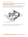
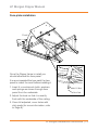
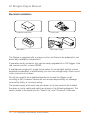
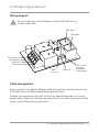
LP Morgan Dipper User Manual
www.lpmorgan.com.au
LP Morgan Dipper Manual
Table of contents
To the owner
3
Face plate installation
13
Unpacking
4
Electrical installation
14
Wiring diagram
15
Dipper views
5-6
Part names and dimensions
7
Cable management
15
Mechanical installation
8
Projector installation
16 - 18
Ceiling opening
9
Accessories
19
Maintenance and
Troubleshooting
20
Warranty Information
21
Ceiling space
10
Ceiling fastening suspended ceiling
11
Ceiling fastening trussed ceiling
12
ATTENTION:
Please read all of these instructions before you operate your Dipper for the
first time. Save these instructions for further reference.
Never operate the Dipper while the projector is still powered!
Information in this document is subject to change without notice.
© Herma Technologies. All rights reserved.
This document is protected against unauthorised copying electronic or otherwise.
Trademarks used in this text: Herma, the Herma Logo, Galleria, LP Morgan and
LP Morgan logo are registered trademarks of Herma Technologies.
Other trademarks and trade names used in this document remain the property
of the relevant owners.
October 2011 Version 2.2
2 | LP Morgan Installation Instructions
LP Morgan Dipper Manual
To the owner
Congratulations on purchasing an Australian made LP Morgan Dipper
motorised projector mount. This innovative projector mounting system is a
novel and secure way to mount your projector out of sight when not in use,
giving you maximum enjoyment and a truly cinematic experience.
Please take a moment to review this manual, as it will ensure you many years
of trouble-free service from your new Dipper.
On Safety
Check that the operating voltage of your unit is identical with the voltage
of your local power supply. If voltage adaptation is required, consult with
qualified an electrician.
Should liquid or solid objects fall into the unit, unplug and have it checked by
qualified personnel before operating it further.
To disconnect the cord, pull it out by the plug. Never pull the cord itself.
The power supply should be near the unit and easily accessible.
The unit is not disconnected from the AC power source as long as it is
connected to the wall outlet, even if the unit has been turned off.
Do not place your hand or other objects near the trapdoor during operation.
The Skyhook projector mount must be used for installation with the Dipper.
On Cleaning
To keep the unit looking new and clean a dust cover is supplied. If cleaning
is necessary use a soft cloth and mild detergent solution. Never use strong
solvents, such as thinners, benzene, or abrasive cleaners.
LP Morgan Installation Instructions | 3
LP Morgan Dipper Manual
Unpacking the Dipper
Control Unit,
Protective Enclosure
LP Morgan Skyhook Projector
Mount System (including
mounting bolts and spacers)
24V Power
Supply
Th
on e F
ly ac
Th with e P
is a lat
wi w e o
l e at n
na er- thi
bl ba s p
e se ro
yo d j e
u un ct
to d o
pa erc r m
in oa ou
ti t n
t t fo t h
o r a
m yo s
at u be
ch r c e
yo on n tr
ur ve ea
ce n i e t e d
ilin nc
g. e.
Dipper Unit
Ceiling Face Plate
Ceiling Trim
Wall Switch and Architrave
Mount
Spring, Bolts Washers
Cardboard Dust cover
When unpacking the Dipper, please handle all parts with care.
Do not destroy the folded inner box when unpacking,
as it is the dust cover for this unit!
4 | LP Morgan Installation Instructions
LP Morgan Dipper Manual
Front view, closed position
Dipper
Size
Overall
Width
(D1)
Face Panel
Width
(D3)
Medium
405mm
400mm
Large
505mm
500mm
D3
D1
Front 3D view
Motor
Pivot Frame
Main Frame
Skyhook Plate
Mounting Tabs
Fro
n
t
Face Panel
LP Morgan Installation Instructions | 5
LP Morgan Dipper Manual
Screen
Top view, closed position
D2 D1
C1
C3
C2
Dipper
Size
Front
mounting
hole (C1)
Overall
Length
(C2)
Rear
mounting
hole (C3)
Overall
Width
(D1)
Mounting
hole Width
(D2)
Medium
15
6500
50
405
380
Large
15
830
40
505
480
All measurements are in millimetres.
6 | LP Morgan Installation Instructions
LP Morgan Dipper Manual
Part names and dimensions
When installing the Dipper, be sure to allow access for future maintenance
requirements of the unit. Wherever possible, allow access to the ceiling cavity
other than through the Dipper’s hole, so that you can access the projector
should the power supply fail!
Side view
A3
A2
A1
B2
B1
B2
Dipper
Size
Front
Mount
Tabs (A1)
Rear
Mount
Tabs (A2)
Overall
Height
(A3)
Face Plate Face Plate Face Plate
to Front
Length
to back
(B1)
(B2)
(B3)
Medium
125
205
355
35
400
215
Large
125
175
430
30
500
300
All measurements are in milimetres.
LP Morgan Installation Instructions | 7
LP Morgan Dipper Manual
Mechanical installation
The first crucial step, like any projector installation, is to determine where
to put the Dipper in the ceiling. The Dipper should be installed so that the
projector lens is centred horizontally to the screen. The distance from the
screen depends on the projector’s throw distance.
Calculate the maximum and minimum throw distances for the projector and
place the Dipper somewhere in between. It is better for the projector to be
closer to the screen, but don’t place it at the extreme end of your calculation.
Allow some room to adjust the zoom in either direction.
Screen
Projector center
Screen center
Lens center
Throw Distance
Note:
When aligning the Dipper make sure that the projector lens is centred on the
screen, which is not necessarily the projector centre.
8 | LP Morgan Installation Instructions
LP Morgan Dipper Manual
Ceiling opening
The Dipper comes with a 12mm undercoated MDF ceiling face plate and an
aluminium ceiling trim.
It is recommended that you paint this panel before installing the Dipper in
the ceiling.
In the case of a non-plasterboard ceiling, you may choose to fabricate your own
ceiling panel (eg. from the same timber/material as the ceiling itself) to match.
It is recommended that you leave a 2mm gap around all edges of the
Dipper’s ceiling face plate.
Supplied is a plastic trim that you may use to finish off the edge of the hole.
The cutout dimensions given below assume that you will use this ceiling trim.
Dipper Size
Face Panel
(L x W)
Cutout required
without ceiling trim
(L x W)
Cutout required
with ceiling trim
(L x W)
Medium
400 x 400
405 x 405
430 x 430
Large
500 x 500
505 x 505
530 x 530
All measurements are in milimetres.
LP Morgan Installation Instructions | 9
LP Morgan Dipper Manual
Ceiling space
The following diagrams show the position of the ceiling cutout in relation to
the Dipper frame, and the space required above the ceiling.
W
L
t
n
Fro
H
L1
L2
Dipper Size
Length
(L)
Width
(W)
Height
(H)
Front Gap
(L1)
Rear Gap
(L2)
Medium
650
405
355
32
212
Large
830
505
430
27
297
All measurements are in millimetres.
10 | LP Morgan Installation Instructions
LP Morgan Dipper Manual
Ceiling fastening - suspended ceiling
For suspended ceilings you can suspend the Dipper itself through the four
mounting holes using the threaded rods.
Threaded rod and nuts
You can use the nuts to adjust the height of the Dipper once installed, so you
can get it exactly flush with the ceiling.
LP Morgan Installation Instructions | 11
LP Morgan Dipper Manual
Ceiling fastening - trussed ceiling
For some ceilings, you will need to construct a support structure for the
Dipper to rest in - this can be as simple as two appropriately spaced bearers
at the right height. See the previous pages for the relevant dimensions.
Screwed straight into bearers
Allow yourself some way to easily adjust the height of the Dipper once
installed, so you can get it exactly flush with the ceiling.
12 | LP Morgan Installation Instructions
LP Morgan Dipper Manual
Face plate installation
Front
Once the Dipper frame is install you
should attached the face panel.
It is recommended that you paint the face
panel to match the room before installing it.
1. Insert 4 x countersunk bolts, washers
and springs as shown through face
panel from the underside.
Spring
M4 Washer
M4 CS Bolt
Stick Pad
2. Adjust the level so that it is exactly
flush with the underside of the ceiling.
3. Once full adjusted, cover holes with
stick pads (for more information, refer
to Page 9).
LP Morgan Installation Instructions | 13
LP Morgan Dipper Manual
Electrical installation
Protective enclosure
Control unit
Wall switch
24V Power supply
The Dipper is supplied with a unique control unit that can be adapted to just
about any installation requirement.
It operates via dry contacts, but can be easily upgraded to a 12V trigger, infra
red, remote control, or even RS232.
A maintained, single pull, single throw switch (a normal light switch) comes
supplied as standard, or alternatively you can use a single relay. Open circuit
is up, close circuit is down.
You do not need to be a qualified electrician to wire the Dipper, as all
circuiting is 24V, however Herma will not accept responsibility for damage
incurred by faulty or incorrect wiring.
The power supply and motor are pre-wired, so all you need to do is attach
the relay or motor cable and switch as shown in the following diagram. The
switch needs to be wired into the “Switch Up” and “Common” terminals.
14 | LP Morgan Installation Instructions
LP Morgan Dipper Manual
Wiring diagram
Do not, under any circumstances, connect 240 VAC to any
of these terminals!
Eye jack
Aux jack
24V Positive
24V Negative
Motor blue
Motor brown
Switch
common
Switch up
Switch down
(not used
in standard
configuration)
Cable management
Every projector has slightly different cable exit positions and because of this,
the Dipper does not have a dedicated cable exit hole.
Instead, we recommend you drill a hole in an appropriate place on the top
timber panel. Make sure to leave enough slack in the cable to account for the
motion of the Dipper during operation.
LP Morgan Installation Instructions | 15
LP Morgan Dipper Manual
Projector installation
The Dipper uses the LP Morgan Skyhook projector mount system.
The parts kit contains:
• 4 x long Skyhook arms,
• 4 x M4, 4 x M5 & 4 x M6
mounting bolts
• 4 x springs
Determine which size mounting
bolts suit your projector, and set
others aside. They are no longer
required.
If your projector has only 3 mounting
holes, remove one of the adjustable arms.
Undo the M8 Nyloc nut, remove an arm,
and replace the nut.
Before connecting the
Skyhook, spread out the arms
so each end is over one of
the mounting holes. If you
feel it necessary, this is an
appropriate time to remove
one or two of the short arms
and replace with the supplied
optional longer arms.
Front of projector
16 | LP Morgan Installation Instructions
LP Morgan Dipper Manual
Connect the Skyhook to projector. Fit the springs between the arms and the
projector, and tighten the mounting bolts so that the projector is parallel to the
triangular plate.
Move the position of the triangular
plate over the centre of the projector,
adjusting the unit so that the edge
with the two holes aligns with the
front of the projector.
Tighten the mounting bolts. The
projector and skyhook system is
ready to be inserted into the Dipper.
Front of projector
LP Morgan Installation Instructions | 17
LP Morgan Dipper Manual
Projector installation
First ensure that the Dipper is operating correctly, and that the projector
cables are properly secured.
Open the Dipper and insert the
triangular projector plate into
the slot in the rear of the Dipper.
Attach it to the front using the
supplied M6 bolts and springs.
M6 Bolt and
washers
Spring
These bolts will also give you Yaw and
Tilt adjustment to align your image on the
screen,while the centre M8 bolt provides Pan
adjustment. The springs will ensure that the
projector is held still during motion. Do not
install the projector plate without springs.
Longer cap screws and extra springs are
supplied if you need extra downwards tilt.
M6 x 75 Cap Screws
M6 x 90 Cap Screws
Tilt
18 | LP Morgan Installation Instructions
Yaw
LP Morgan Dipper Manual
Accessories
The following Dipper accessories are also avilable from LP Morgan.
Contact your local retailer for pricing information.
Triggering From Projector:
HER20HD12V: 12 volt trigger unit for projectors with
a 12 volt trigger output.
• Often used also with LPM43SCR12V:
Screen 12V Trigger
HER20HD12V and LPM48HDSCRTRIG: Trigger Unit
for Projectors without a 12 Volt Trigger
• Uses current sensing to detect when the projector
is on.
• Triggers a screen as well.
• Includes an IR repeater kit.
Infra Red Remote Control:
HER20HDIRKIT: Infra Red remote control and receiver
RS232 Integration:
LPM43MULTI: RS232 Interface for both
Projector Mount and Screen Controls.
LP Morgan Installation Instructions | 19
LP Morgan Dipper Manual
Maintenance and troubleshooting
The unit has stopped working and won’t go up or down:
1. Check that all the terminations are secure, that the power supply is
plugged in and that the cables are free from damage.
2. A light on the power supply indicates power - if it is off, then the power
supply may be damaged.
3. Open the black plastic enclosure to expose the control board. Switch
the power off and on. You will see a LED flash on the circuit board which
indicates power, and that the circuit board is operating correctly.
4. Close the Switch “Up” and “Common” terminals on the control board (refer
to page 15 for a wiring diagram). If the unit does not move, but you hear a
“clicking” sound then the motor may be damaged. Contact Herma for advice.
5. If you have been repeatedly operating the Dipper, the motor may have
reached a thermal cutout and won’t operate. Wait five minutes for it cool
and try again.
6. If you have integrated the Dipper into a control system (eg. projector
triggering, IR repeating, Crestron, AMX, etc.) then the problem is most
likely with the control system! Check that the right signal is getting to
the Dipper. Use the wall switch (close the Switch “Up” and “Common”
terminals) to test the unit.
I can’t get enough downwards tilt on my projector:
We have supplied long (75mm), and extra-long (95mm) M6 caps screw bolts
if you need to angle the projector further down. Use the extra springs (also
supplied) to keep the Skyhook plate tightly secured.
20 | LP Morgan Installation Instructions
LP Morgan Dipper Manual
Warranty Information
Keep your original receipt for warranty.
Please fill out the online warranty form in order to qualify for the manufacturer’s warranty.
http://www.lpmorgan.com.au/owners.html
The warranty covers defects in workmanship and materials, provided this product
has been installed in a normal environment and maintained according to the written
instructions. Herma warrants the product against loss of usefulness, discolouration or
deterioration of optical quality within the warranty period as a result of manufacturing or
material defects. This warranty applies only within Australia.
Please return your goods to the place of purchase for all warranty claims.
Conditions
Any equipment replaced pursuant to the terms of this warranty shall be retained
by Herma.
All costs related to de-installation and re-installation of the product covered by this
warranty are not the responsibility of Herma Technologies. Herma will not be responsible
for any consequential damages during or following installation procedures.
Herma is not responsible for any freight costs relating to repair or replacement.
Equipment must be returned to Herma in suitable packing to prevent damage in
transit. Herma will not accept any responsibility for damage to the equipment caused
by inadequate or unsuitable packing, or for any damage howsoever caused whilst the
goods are in transit.
Herma Technologies shall not be liable for any injury, loss or damage, direct or
consequential, arising out of the use of, misuse of, or inability to use, the equipment.
This Warranty does not cover any product which has been subjected to misuse,
abuse, neglect, accidental or intentional damage, improper voltage or any alteration
which affects the reliability or performance of the equipment not attributable to faulty
manufacture, parts or labour and without limiting the generality of the foregoing.
This Warranty does not cover any product where usage, adaptation or installation
are not in accordance with our written installation and operating instructions.
Warranty Period:
Two years from date of purchase.
LP Morgan Installation Instructions | 21
For more information on our range of products,
please visit www.lpmorgan.com.au, or contact
your local LP Morgan Retailer.
Factory 4a, 6 Albert Street Preston Vic 3072
Phone: +61 3 9480 6233 Fax: +61 3 9480 6533
Email: [email protected] www.lpmorgan.com.au
October 2011 Version 3.1