1
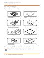
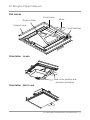
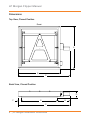
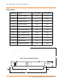
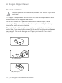
LP Morgan Flipper User Manual
www.lpmorgan.com.au
LP Morgan Flipper Manual
Table of contents
To the owner
3
Projector installation
14 - 15
Unpacking
4
Flipper Skyhook unit
16
Part names
5
Cable management
17
Dimensions
6-7
Multiflip
18 - 19
Mechanical installation
8
Dust cover fitting
20
Ceiling opening
9
Accessories
21
Maintenance and
Troubleshooting
22
Warranty Information
23
Ceiling space
10 - 11
Electrical installation
12
Wiring diagram
13
ATTENTION:
Please read all of these instructions before you operate your Flipper for the
first time. Save these instructions for further reference.
Never operate the Flipper while the projector is still powered!
Information in this document is subject to change without notice.
© Herma Technologies. All rights reserved.
This document is protected against unauthorised copying electronic or otherwise.
Trademarks used in this text: Herma, the Herma Logo, Galleria, LP Morgan and
LP Morgan logo are registered trademarks of Herma Technologies.
Other trademarks and trade names used in this document remain the property
of the relevant owners.
October 2011 Version 2.2
2 | LP Morgan Installation Instructions
LP Morgan Flipper Manual
To the owner
Congratulations on purchasing an LP Morgan Flipper. This innovative
projector mounting system is a novel and secure way to mount your projector
out of sight when not in use, giving you maximum enjoyment and a truly
cinematic experience.
Since the Flipper was first released in 2004, we have added some new
features that makes the Flipper even more versatile:
• Multiflip - for installation at any angle (even in a wall!)
• Stall Sensing - for installation in a tabletop/bench. Current sensor detects
an obstruction and will stop the unit for added safety.
Please take a moment to review this manual, as it will ensure you many years
of trouble-free service from your new Flipper.
On Safety
Check that the operating voltage of your unit is identical with the voltage
of your local power supply. If voltage adaptation is required, consult with a
qualified electrician.
Should liquid or solid objects fall into the unit, unplug and have it checked by
qualified personnel before operating it further.
To disconnect the cord, pull it out by the plug. Never pull the cord itself.
The power supply should be near the unit and easily accessible.
Do not place your hand or other objects near the trapdoor during operation.
The Skyhook Projector Mount must be used for installation with the Flipper.
On Cleaning
To keep the unit looking new and clean a dust cover is supplied. If cleaning
is necessary use a soft cloth and mild detergent solution. Never use strong
solvents, such as thinners, benzene, or abrasive cleaners.
LP Morgan Installation Instructions | 3
LP Morgan Flipper Manual
Unpacking the Flipper
Supplied parts (accessories list)
Powdercoated steel frame and
pivot assembly
Undercoated timber panel
(affixed)
LP Morgan Skyhook Projector
Mount System (including
mounting bolts and spacers)
Control Unit
12V Power Supply
Aluminium Ceiling Trim
Wall Switch and
Architrave Mount
Cardboard Dust cover
When unpacking the Flipper, please handle all parts with care.
Do not destroy the folded inner box when unpacking,
as it is the dust cover for this unit!
4 | LP Morgan Installation Instructions
LP Morgan Flipper Manual
Part names
Pivot Frame
Skyhook Plate
Motor
Flipper Frame
Limit Switches
NT
O
FR
Orientation - In use
Note motor position and
projector orientation
Orientation - Not in use
LP Morgan Installation Instructions | 5
LP Morgan Flipper Manual
Dimensions
Top View, Closed Position
Front
A
B
C
Back View, Closed Position
D
F
G
E
C
6 | LP Morgan Installation Instructions
LP Morgan Flipper Manual
Dimensions
Dimension Name
Std Flipper
Lrg Flipper
A
Overall Length
575
675
B
Frame Width
515
625
C
Overall Width
670
770
D
Closed Height
84
84
E
Face Panel Width
450
550
F
LHS Panel Offset
40
40
G
RHS Panel Offset
180
180
H
Face Panel Length
500
600
I
Rear Offset
37.5
37.5
J
Front Offset
37.5
37.5
K
Operating Height
350
400
K
Side View, Closed Position
Front
H
I
D
J
A
LP Morgan Installation Instructions | 7
LP Morgan Flipper Manual
Mechanical Installation
The Flipper may be installed through its own hole if required.
The first crucial step, like any projector installation, is to determine where
to put the Flipper in the ceiling. The Flipper should be installed so that the
projector lens is centered horizontally to the screen, and the distance from the
screen depends on the projector’s throw distance.
Work out the maximum and minimum throw distances for the projector and
place the Flipper somewhere in between. It is better for the projector to be
closer to the screen, but don’t place it at an extreme—leave yourself some
room to adjust the zoom in either direction.
Screen
Projector centre
Screen centre
Lens centre
Throw Distance
Note:
When aligning the Flipper make sure that the projector lens is centred on the
screen, which is not necessarily the projector centre.
8 | LP Morgan Installation Instructions
LP Morgan Flipper Manual
Ceiling opening
The Flipper was designed by an installer, with the installer in mind. The face
panel that is supplied is 18mm undercoated MDF, and is easily removed via
six screws.
We recommend that you remove and paint this panel before fixing the Flipper
in the ceiling.
In the case of a non-plasterboard ceiling, you may choose to fabricate your own
ceiling panel (eg. from the same timber/material as the ceiling itself) to match.
The Ceiling trim we supply will leave a 2mm clearance on all sides of this
face panel.
If you choose not to use this ceiling trim, you should be aware that you will
need to allow more clearance at the front and back of the panel, because the
trajectory traced by the ceiling panel is actually wider than the ceiling trim.
For a Standard Flipper
Length
Width
Face Panel
500
450
Cutout required, if NOT using the supplied trim
508
454
Cutout required, if using the supplied trim
528
478
Length
Width
Face Panel
600
550
Cutout required, if NOT using the supplied trim
608
554
Cutout required, if using the supplied trim
628
578
For a Large Flipper
LP Morgan Installation Instructions | 9
LP Morgan Flipper Manual
Ceiling Space
The following diagrams show the position of the ceiling cutout in relation to the
Flipper frame, the space required above the ceiling, and the mounting hole
positions.
The Flipper has been designed to be compatible with just about any installation
situation. You should be able to adapt the Flipper to suit your specific installation
requirements.
The Flipper frame is designed to sit 12.5mm above the ceiling—that is, it virtually
rests on the plaster!
Where possible, install the Flipper in such a way that you can micro adjust
the height so you can get it exactly flush with the ceiling, eg. suspended from
threaded rod.
T
K
ON
FR
M
O
A
N
L
M
10 | LP Morgan Installation Instructions
P
C
LP Morgan Flipper Manual
Dimension Name
Std Flipper
Lrg Flipper
A
Overall Length
575
675
C
Overall Width
670
770
K
Operating Height
350
400
L
Cutout Length
528
628
M
Front & Back Offset
23.5
23.5
N
Cutout Width
478
578
P
Left Offset
26
26
O
Right Offset
166
166
Q
Widthways Hole Spacing
500
600
R
Lengthways Hole Spacing
558
658
S
Hole Offset
8
8
T
Right Hole Offset
162
162
T
ON
FR
S
T
A
R
Q
S
C
S
LP Morgan Installation Instructions | 11
LP Morgan Flipper Manual
Electrical Installation
Do Not, under any circumstances, connect 240 VAC to any of these
terminals!
The Flipper is supplied with a 12V control unit that can be operated by either
close contacts or the supplied wall switch.
You do not need to be a qualified electrician to wire the Flipper, as all
circuiting is 12V, however Herma will not accept responsibility for damage
incurred by faulty or incorrect wiring.
The motor, limit switches and power supply are supplied pre-wired into the
control box. If you need to disconnect them, use the following wiring diagram
very carefully. You could damage your Flipper permanently if you wire it
incorrectly!
Control Unit
12V Power Supply
Wall Switch and
Architrave Mount
12 | LP Morgan Installation Instructions
LP Morgan Flipper Manual
Wiring Diagram
We supply these units pre-programmed to operate via a maintained SPST
switch (a single throw relay). The supplied switch should be connected to the
“Up” and “Common” terminals ONLY.
Should you wish to use a different sort of switching method (eg. SPDT), you
can easily program the device to do so. However, you will need a receiver
eye and special programming remote (available as our Installer’s Kit LPM43INSKIT)
EYE
K
JAC
AUX
K
JAC
12V Positive
12V Negative
Switch Down
Motor Blue
Motor Brown
Switch Common
Switch Up
(Not used
in standard
configuration)
Use a small flat
screwdriver to prise
open the motor and
mains terminals
Stall Sensing
These control units have an in-built stall sensor which is a necessary feature if
you are installing a Flipper into a tabletop.
To activate the stall feature you need to purchase a programmer’s kit
(LPM43INSKIT) has included detailed instructions on setting a calibrating the
current threshold.
Contact Herma if you want further information on stall settings.
LP Morgan Installation Instructions | 13
LP Morgan Flipper Manual
Projector Installation
The Flipper uses the LP Morgan Skyhook projector mount system.
Step 1
The parts kit contains:
• 4 x long Skyhook arms,
• 2 x short Skyhook arms,
• 4 x M4, 4 x M5 & 4 x M6
mounting bolts,
• 4 x springs.
Determine which size mounting
bolts suit your projector, and set
others aside. They are no longer
required.
Step 2
If your projector has only 3 mounting
holes, remove one of the adjustable
arms. Undo the M8 Nyloc nut, remove
an arm, and replace the nut.
Step 3
Before connecting the Skyhook, spread
out the arms so each end is over one of
the mounting holes. If you feel it necessary,
this is an appropriate time to remove 1 or
2 of the short arms and replace with the
supplied optional longer arms .
Front of projector
14 | LP Morgan Installation Instructions
LP Morgan Flipper Manual
Step 4
Connect Skyhook to Projector. Fit the springs between the arms and the
projector, and tighten the mounting bolts so that the projector is parallel to
the triangular plate.
Step 5
Move the position of the triangular
plate over the centre of the projector,
with the edge with the 2 holes towards
the front.
Front of projector
Step 6
Tighten the mounting bolts.
The projector and Skyhook
system is ready to be
inserted into the Flipper.
LP Morgan Installation Instructions | 15
LP Morgan Flipper Manual
Flipper Skyhook unit
First ensure that the Flipper is operating correctly, and that the projector
cables are properly secured.
Open the Flipper and bolt the
triangular projector plate to the
underside of the Flipper using the
supplied M6 bolts and springs.
M6 Bolt and
Washer
Spring
Detail: M6 bolts and Spring
These bolts will also give you Yaw and Tilt adjustment to align your image on
the screen, while the centre M8 bolt provides Pan adjustment. The springs will
ensure that the projector is held still during motion. Do not install the projector
plate without springs.
Extra Adjustment
You can fine tune the open and closed positions of the Flipper by adjusting
the angle of the two limit arms on each side of the pivot frame (see page 5 for
part names).
These arms hit the limit switches in the closed and open positions.
16 | LP Morgan Installation Instructions
LP Morgan Flipper Manual
Cable Management
Because every projector has a different point of access for its mounting
points and cable, the Flipper provides an exit opening on the side of the
pivot frame for the projector cables. There are two holes near this cutout that
you may use to tie off the cables, so that they are firmly secured.
Ensure that you leave enough slack for the cables, so that the cable will not
interfere with the motion of the unit.
Cable management
LP Morgan Installation Instructions | 17
LP Morgan Flipper Manual
Mulitiflip
The multiflip bracket is an accessory that allow you to install the Flipper into
an angled ceiling or even a wall.
You do not need to use the multilfip if installing into a horizontal ceiling or tabletop.
Step 1
Remove one of the limit arms (the one that sets the open position and attach
it to the multiflip bracket as shown, using the supplied M6 x 10 Bolt.
Step 2
Attach the mutliflip bracket to the Flipper as shown, using another of the
M6 x 10 Bolts.
Position of Adjuster Arm determines
stopping angle of Flipper
18 | LP Morgan Installation Instructions
LP Morgan Flipper Manual
Step 3
Adjust the position of the Limit Arm to give you the desired stopping angle
Limit arm
engages limit
switches
Flipper in
Angled Ceiling
Projector is Horizontal
when in use
LP Morgan Installation Instructions | 19
LP Morgan Flipper Manual
Dust Cover Fitting
We supply a folded cardboard box as a dust cover for the Flipper. Cardboard
is much more environmentally friendly than plastic, cheaper and is easily
modified to suit your specific installation.
Note:
You may need to cut the dust cover to fit around/over bearers in the ceiling.
1
2
3
5
4
Double Sided
Adhesive Pad
20 | LP Morgan Installation Instructions
Space for
the Motor
6
LP Morgan Flipper Manual
Accessories
The following accessories are also available from LP Morgan.
Contact your local retailer for pricing information.
Triggering From Projector:
HER20HD12V: 12 volt trigger unit for projectors with
a 12 volt trigger output.
• Often used also with LPM43SCR12V:
Screen 12V Trigger
LPM48HDSCRTRIG: Trigger Unit for
Projectors without a 12 Volt Trigger
• Uses current sensing to detect when the
projector is on.
• Triggers a screen as well.
• Includes an IR repeater kit
Infra Red Remote Control:
HER20HDIRKIT: Infra Red remote control and receiver
Radio Frequency Remote Control:
HER20HDRFKIT: Radio Frequency remote
control and receiver
RS232 Integration:
LPM43MULTI: RS232 Interface for both
Projector Mount and Screen Controls.
LP Morgan Installation Instructions | 21
LP Morgan Flipper Manual
Maintenance and Troubleshooting
The unit has stopped working and won’t go up or down:
1. Check that all the terminations are secure, that the power supply is
plugged in and that the cables are free from damage.
2. A light on the power supply indicates power - if it is off, then the power
supply may be damaged.
3. Open the black plastic enclosure to expose the control board. Switch
the power off and on. You will see a LED flash on the circuit board which
indicates power, and that the circuit board is operating correctly.
4. Close the Switch “Up” and “Common” terminals on the control board (refer
to page 17 for a wiring diagram). If the unit does not move, but you hear
a “clicking” sound then the motor may be damaged. Contact Herma for
advice.
If you have integrated the Flipper into a control system (eg. Projector
triggering, IR repeating, Crestron, AMX, etc) then the problem is most likely
with the control system! Check that the right signal is getting to the Flipper.
Use the wall switch (close the Switch “Up” and “Common” terminals) to test
the unit.
If it still doesn’t work, Contact Herma for advice.
The projector cables get jammed in the pivot frame as it rotates:
Check that the cutout for the projector cable is on the right side – NOT THE
MOTOR SIDE.
You may have it installed upside down! Check the diagram on page 10 and
take careful note of the motor and projector orientation.
The unit may be turning the wrong way – if this is so, it will damage the
microswitches as it turns. Contact Herma for advice.
The Face panel is not squared/centred in the trim:
Loosen the 6 screws (but don’t undo!), and you will be able to adjust the
position of the face panel slightly (by about 2mm)– since the holes the screws
go through are a 2mm larger than the screws.
22 | LP Morgan Installation Instructions
LP Morgan Flipper Manual
Warranty Information
Keep your original receipt for warranty.
Please fill out the online warranty form in order to qualify for the manufacturer’s warranty.
http://www.lpmorgan.com.au/owners.html
The warranty covers defects in workmanship and materials, provided this product
has been installed in a normal environment and maintained according to the written
instructions. Herma warrants the product against loss of usefulness, discolouration or
deterioration of optical quality within the warranty period as a result of manufacturing or
material defects. This warranty applies only within Australia.
Please return your goods to the place of purchase for all warranty claims.
Conditions
Any equipment replaced pursuant to the terms of this warranty shall be retained
by Herma.
All costs related to de-installation and re-installation of the product covered by this
warranty are not the responsibility of Herma Technologies. Herma will not be responsible
for any consequential damages during or following installation procedures.
Herma is not responsible for any freight costs relating to repair or replacement.
Equipment must be returned to Herma in suitable packing to prevent damage in
transit. Herma will not accept any responsibility for damage to the equipment caused
by inadequate or unsuitable packing, or for any damage howsoever caused whilst the
goods are in transit.
Herma Technologies shall not be liable for any injury, loss or damage, direct or
consequential, arising out of the use of, misuse of, or inability to use, the equipment.
This Warranty does not cover any product which has been subjected to misuse,
abuse, neglect, accidental or intentional damage, improper voltage or any alteration
which affects the reliability or performance of the equipment not attributable to faulty
manufacture, parts or labour and without limiting the generality of the foregoing.
This Warranty does not cover any product where usage, adaptation or installation
are not in accordance with our written installation and operating instructions.
Warranty Periods:
Two years from date of purchase.
LP Morgan Installation Instructions | 23
For more information on our range of products,
please visit www.lpmorgan.com.au, or contact
your local LP Morgan Retailer.
Factory 4a, 6 Albert Street Preston Vic 3072
Phone: +61 3 9480 6233 Fax: +61 3 9480 6533
Email: [email protected] www.lpmorgan.com.au
October 2011 Version 2.2