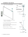
1
LP morgan
POP Screen
user manual
www.lpmorgan.com.au
Notes and Cautions
TIP: A tip indicates important information that helps you make better use of your screen.
WARNING: A notice indicates potential damage to ceiling and tells you how to avoid the problem.
DANGER: A caution indicates a potential for property damage, personal injury or death.
Table of contents
Important information
Unpacking
3
Installation
Installation - Top Grip Kit
4
Installation - Side Grip Kit
5
Installation - Stabilising Bars
6
Installation - Framed Screens
7
Appendix
Maintenance & Troubleshooting
10
Warranty Information
11
To the owner
Congratulations on purchasing an LP Morgan Pop Screen. A high quality,
rigid and low cost rear projection screen, designed for visual merchandising
applications. Please take a moment to review this manual, it will ensure
you many years of trouble-free service from your new POP Screen vertical
mounting kit.
Information in this document is subject to change without notice.
© 2002-2006 Herma Technologies. All rights reserved.
Reproduction in any manner whatsoever without permission of Herma Technologies is strictly forbidden.
Trademarks used in this text: Herma, the Herma Logo, LP Morgan and LP Morgan logo are registered
trademarks of Herma Technologies.
Other trademarks and trade names may be used in this document to refer to either the entities claiming the
marks and names or their product. Herma Technologies disclaims interest in trademarks and trade names
other than its own.
Apr 2006
Version 4.1
Unpacking the Pop Screen
Depending on the size of the screen chosen and the configuration
you have chosen to mount your screen, you should have a selection
of the components shown below:
2 x 2m Cable with top
grip suspension kit
Important
information
Supplied
2 x 2m Cable with side
grip suspension kit
7
Stabilising bar kit (for 45’’, 49”, 60” & 69” size screens only):
2 x Stabilising Bars 10 x Screen Grips
4 x End Caps
2 x Sliding mounts
misc:
1 x POP screen
cut to size
2 x M4x12
Grub Screws
Frame Kits (NB: frame is pre-assembled if size is either 77” or 84”)
4 x Pieces of frame
extrusion
4 x corner
bracket plate
4 x corner
bracket
8 x M6 grub
screws
M6 x 12 bolts
2 x frame tabs
2 x slide nuts
installation instructions | 3
Installation: Top Grip Kit
Detail B
Fig 1: Top Grip Assembly
Top
Boss
Fig 2:
B
Top Grip Hanging
Kit detail Assembly
Mechanical
Installation
A
to ceiling
B-1
1. Position universal grips to POP Screen
(See fig 1. and Detail-A)
2. A-1 to secure wire; then A-2 to secure screen.
universal
grip
3. Screw top boss to ceiling
(See Fig 2, Detail-B) Determine desired screen
height, trim wire to length.
(Default wire length = 2000mm).
Detail A
4. Secure wire at the top with grub screw B-1
A-1
A-2
4 | installation instructions
Installation: Side Grip Kit
Fig. 4a:
(Detail A)
Fig 4: Side Grip Assembly
Detail B
2. Secure
wire
1. Secure
to screen
Detail A
Mechanical
Installation
Fig 5: Side Grip Hanging
Kit Assembly detail
(Detail B)
boss
1. Attach universal grip to POP Screen (See Fig 4a,
step 1) using 2mm allen key (supplied) to tighten M4
grub screw.
2. Screw bosses to ceiling (or wall) - See Fig 5 at the
appropriate spacing (depending on the size of the
screen.
3. Determine desired cable length and trim
appropriately.
4. Screw bottom boss to floor (or wall) (See Detail B)
5. Attach side grips to cable (see Fig. 4a step 2) and
secure screen at the desired height.
installation instructions | 5
Installation: Stabilising Bars
1. Remove plastic caps on both ends of top and bottom stabilising bars and
remove clear plastic slide out screen grips (see fig. 6a)
2. Attach plastic grips to top and bottom edges of POP Screen. Make sure
they are securely fastened. Slide in plastic slider into top stabilising bar.
Mechanical
Installation
3. Slide in screen with screen grip attached into channel of top and bottom
stabilising bars. Replace
4. Secure Top Bosses (See fig 2 - Detail B) to ceiling at the appropriate
spacing (this depends on the size of the screen).
5. Determine desired cable length and trim appropriately.
6. Secure universal grip to top stablising bar (see fig. 6b).
Fig 6a: Stabilising Bar Assembly Detail
plastic slider
Fig 6b: Universal grip
attachment detail
Remove plastic caps
Slide out screen grips
Tighten
Fig 7: Assembled POP Screen with Stabilising Bars
Mounting Surface
6 | installation instructions
Installation: Framed Screens
Frame Assembly:
• Note: If your screen has been pre-assembled, proceed to page 9.
1. Place two slide nuts into channel of frame section which is intended to
be directly above top edge of image.
2. With frame pieces overturned, place corner bracket on corner bracket
plate and slide both into channel as far as possible as shown in fig. 8.
3. Tighten M6 grub screw using a flathead screwdriver.
5. Position and align frame sections, tighten remaining grub screws to
secure the frame.
Mechanical
Installation
4. Repeat for three other corners placing brackets and frame pieces in
position as shown in fig. 9
3
Fig. 8:
Frame Assembly detail
Tighten
Corner bracket
1
2
Place slide nuts
into this channel.
Corner bracket
plate
Fig. 9: Bracket fixturing for frame assembly.
5
Position &
align frame
sections
installation instructions | 7
Installation: Framed Screens
Screen Assembly:
1. Place the frame face up on a flat and stable
surface.
Mechanical
Installation
2. Open the frame covers (located along the inner
edge of the frame). To do this, reach inside of inner
edge of frame and pull frame covers toward outer
edge of frame.
3. Repeat for three other edges.
4. Place screen into the frame so that it is securely
housed into the base of the frame.
5. Close all four opened frame covers over the frame.
Fig 10: Securing the screen into the frame
Place screen
into the frame
Open Frame
cover
8 | installation instructions
Installation: Framed Screens
Hanging Attachments and Configuration:
1. Determining appropriate spacing between hanging cables, secure
top grip kits to ceiling. See page 4 of this instruction manual on details
of how to do this.
2. Secure frame tabs to frame with M6 bolt passing through larger hole
of frame tab to slide nut inside of frame channel.
3. Your framed POP screen should appear as that depicted in fig 12.
Universal
Grip
M6x12
Bolt
secure frame tab
with grub screw.
To slide nut
Mechanical
Installation
Fig 11: Hanging detail for framed screens.
Frame tab
Fig 12 : Suspended Frame with Top Grip Suspension Kit
Mounting Surface
See Fig 2 for Hanging
kit installation
installation instructions | 9
Maintenance and troubleshooting
Cleaning instructions:
The screen surface on your Pop Screen is extremely delicate. Special attention
to these instructions should be followed when cleaning.
1. A draftsman’s style brush may be used to lightly whisk away any loose dirt or
dust particles. Do not use a sharp instrument to remove any particles. Softly
brush from the centre to the edges.
2. The screen may be cleaned with a mild solution of detergent and water and
a sponge or soft lint free cloth. Rub lightly to remove any stubborn marks, then
blot with a damp sponge to absorb excess water. Use a clean sponge with
clear water to wash off the detergent residue. Dry the screen with a soft cloth/
towel so that the detergent does not have time to dry on the screen.
3. NEVER attempt to use solvents, chemicals or abrasive cleaners on the
screen.
Maintenance &
Troubleshotting
4. We encourage you to keep your screen clean. Avoid getting any foreign
materials on it, as cleaning may prove to be very difficult or even impossible
(scratches, paint, ink, etc.). Never paint in the vicinity of the screen unless the
screen surface is completely protected.
With reasonable care you may expect years of trouble free use of your LP
Morgan POP screen.
10 | installation instructions
Warranty Information
Customers must fill out the online warranty form, or the warranty card included with the
product and post it back to Herma at the reply paid address shown on the back cover in
order to qualify for the manufacturer’s warranty.
www.herma.com.au/warranty
The warranty covers defects in workmanship and materials, provided this product
has been installed in a normal environment and maintained according to the written
instructions. Herma warrants the product against loss of usefulness, discolouration or
deterioration of optical quality within the warranty period as a result of manufacturing or
material defects. This warranty applies only within Australia.
CONDITIONS –
Herma will repair or replace, with the least possible delay, any defective equipment. Any
equipment replaced pursuant to the terms of this warranty shall be retained by Herma
All costs related to installation and re-installation of the Herma equipment covered by this
warranty are not the responsibility of Herma Technologies. Herma will not be responsible
for any consequential damages during or following installation procedures.
The user is responsible for any freight costs relating to repair or replacement. Equipment
must be returned to Herma in suitable packing to prevent damage in transit. Herma
will not accept any responsibility for damage to the equipment caused by inadequate
or unsuitable packing, or for any damage howsoever caused whilst the goods are in
transit.
Herma Technologies shall not be liable for any injury, loss or damage, direct or
consequential, arising out of the use of, misuse of, or inability to use, the equipment.
Warranty Period: 2 years
installation instructions | 11
Appendix
This Warranty does not cover any equipment which has been subjected to misuse,
abuse, neglect, accidental or intentional damage, improper voltage or any alteration
which affects the reliability or performance of the equipment not attributable to faulty
manufacture, parts or labour and without limiting the generality of the foregoing shall not
apply where the defect arose as the result of the following circumstances:
This Warranty does not cover any equipment where usage, adaptation or installation
(including wiring of electrical connections) are not in accordance with our written
installation and operating instructions.
Your LP Morgan Retailer is able
to provide information on your
product. If we can be of any further
help, please contact us.
Factory 4a, 6 Albert Street Preston Vic 3072
Phone: +61 3 9480 6233
Fax: +61 3 9480 6533
Email: [email protected]
www.lpmorgan.com.au