1
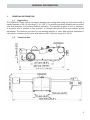
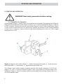
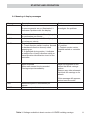
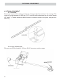
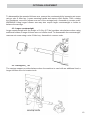
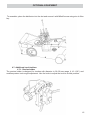
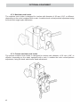
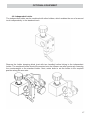
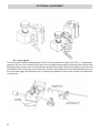
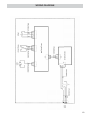
DRAGON
FLAME CUTTING CARRIAGE
OPERATOR’S MANUAL
BEFORE USE, ENSURE EVERYONE USING THIS MACHINE READS AND UNDERSTANDS
ALL SAFETY AND OPERATING INSTRUCTIONS IN THIS MANUAL .
Serial #............................................
1
Date of Purchase............................
TRADEMASTER DRAGON FLAME CUTTING CARRIAGE
IMPORTED & DISTRIBUTED BY
INDUSTRIAL TOOL & MACHINERY SALES
INDUSTRIAL TOOL
T
F
E
W
18 BUSINESS ST
YATALA QLD 4207 AUSTRALIA
07 3287 1114
07 3287 1115
[email protected]
www.industrialtool.com.au
WARRANTY TERMS
In addition to any warranties or conditions implied by applicable Statute or Regulations, Industrial Tool & Machinery
Sales warrants all of it’s products against defective workmanship and faulty materials for a period of twelve (12)
months from the date of purchase, unless otherwise stated. At our option we will repair or replace, free of charge,
any item on the condition that:
• The complete machine or tool is returned, freight prepaid to ITM or one of it’s authorised service agents as
directed by ITM, and is found to have a material or constructional defect.
• The machine or tool has not been subject to misuse, neglect or damage by accident.
• The fault is not a result of normal “wear and tear”.
• Written permission has been received from ITM prior to commencement of repair.
• Repairs, tampering or modification carried out by unauthorised personnel will void all warranty.
• Consumable items such as cutting tools, pilot pins, saw blades, grinding wheels etc. are NOT covered by
warranty.
Our goods come with guarantees which cannot be excluded under the Australian Consumer Law. You are entitled to
replacement or refund for a major failure and to compensation for other reasonably foreseeable loss or damage. You
are also entitled to have the goods repaired or replaced if the goods fail to be of acceptable quality and the failure
does not amount to a major failure.
TABLE OF CONTENTS
2
1. GENERAL INFORMATION.................................... 3
1.1. Application.................................................. 3
1.2. Technical data............................................ 3
1.3. Design........................................................ 4
1.4. Equipment included.................................... 5
2. SAFETY PRECAUTIONS...................................... 6
3. STARTUP AND OPERATION............................... 8
3.1. Preparing to operation................................ 8
3.2. Operation.................................................... 9
3.3. Changing unit of speed............................... 9
3.4. Meaning of display messages.................... 11
4. OPTIONAL EQUIPMENT...................................... 12
4.1. Track way................................................... 12
4.2. Longer follower arm.................................... 12
4.3. Larger counterweight.................................. 13
4.4. Carriage support......................................... 13
4.5. Cable holder............................................... 14
4.6. Gas distributor............................................ 14
4.7. Additional torch holders.............................. 15
4.7.1. Precise holder............................................. 15
4.7.2. Machine torch holder.................................. 16
4.7.3. Precise machine torch holder..................... 16
4.8. Independent holder..................................... 17
4.9. Circle guide................................................. 18
5. WIRING DIAGRAM................................................ 19
GENERAL INFORMATION
1.
GENERAL INFORMATION
1.1. Application
The DRAGON Flame Cutting Carriage is designed for cutting steel using oxy fuel torches with a
handle diameter in 28–35 mm range (1.10–1.38’’). The machine performs straight-line horizontal
cuts with maximum 10º working material inclination. The machine is easy to use, to transport,
to maintain and to position in the worksite. It contains rear-wheel drive and enables speed
adjustment. The machine can travel on the working material or track. With optional equipment it
can use two torches and cut holes with radius in 240–1000 mm range (9.4–39.4’’).
1.2.
Technical data
3
GENERAL INFORMATION
Oscillation type
Power
Operating position
Torch diameter
Ground clearance
Speed
Dimensions
Weight
115-230 V, 50-60 Hz
20 W
horizontal
28–35 mm (1.10–1.38’’)
7.5 mm (0.30’’)
0–150 cm/min (0–59.0’’/min)
473 mm (L) × 655 mm (W) × 182 mm (H)
18.6’’ (L) × 25.8’’ (W) × 7.2’’ (H)
16.8 kg (37.0 lbs)
1.3. Design
DRAGON Flame Cutting Carriage contains drive system with controller, follower arm,
counterweight and angular torch holder. The drive system comprises a gear-motor that drives
two steel wheels. The machine is equipped with a coupling that enables the user to disconnect
the drive using a knob (Figure 1, Item 8) and then perform manual travel of the carriage.
Figure 1. DRAGON flame cutting carriage design: 1 – drive system, 2 – control panel,
3 – angular torch holder, 4 – follower arm, 5 – follower arm position handwheel,
6 – counterweight, 7 – power supply socket, 8 – coupling knob, 9 – carrying handle
4
GENERAL INFORMATION
Figure 2. Control panel design: 1 – LED display, 2 – speed adjusting knob, 3 – power switch,
4 – travel direction switch (forwards / 0 / backwards)
1.4. Equipment included
DRAGON flame cutting carriage is supplied with all the standard equipment packaged in a
foam filled cardboard box. The included equipment consists of:
•
•
•
•
•
•
•
•
•
•
•
Flame Cutting Carriage
Foam filled Cardboard Box
Follower Arm of 580 mm (22.8’’)
Counterweight of 1.3 kg (2.9 lbs)
Angular Torch Holder
Power Cord
Size 2.5 Allen Key
Size 3 Allen Key
size 4 Allen Key
Size 5 Allen Key
Operator’s Manual
– 1 unit
– 1 unit
– 1 unit
– 1 unit
– 1 unit
– 1 unit
– 1 unit
– 1 unit
– 1 unit
– 1 unit
– 1 unit
5
SAFETY PRECAUTIONS
2. SAFETY PRECAUTIONS
Using the machine is not allowed if:
1.
2.
3.
4.
5.
6.
7.
Operator has not read Operator’s Manual or has not completed proper occupational
safety and health training.
Machine is to be used in applications not stated in Operator’s Manual.
Machine is not complete or parts used for repair are not genuine.
Power supply specifications do not conform to those stated on rating plate.
Operator has not checked condition of machine, including power cord and control
panel components.
Power supply socket is not equipped with earthing pin.
Bystanders are present in immediate vicinity of machine.
Detailed safety rules:
1)
2)
3)
4)
5)
6)
7)
8)
9)
10)
11)
12)
13)
14)
15)
16)
6
Before you start to work with the machine, check the condition of the electrical
installation, including the power cord and plug.
Connect the machine only to an installation equipped with a safety circuit (earthing)
protected with a 16 A fuse for a 230 V supply. When used on building sites, supply
power to the machine through a separation transformer made in the second protection
class.
Never carry machine by the cord or yank it to disconnect plug from socket. It may
cause the power cord to break and result in electric shock!
Keep the machine dry. Exposing it to rain or snow is prohibited.
Ensure proper lighting in your worksite.
Never use the machine in the vicinity of combustible fluids or gases or in an explosive
environments.
Transport and position machine using carrying the handle.
Do not stay underneath the machine when it is placed at heights.
Plug the power cord into the mains only when the power switch is set to “0” position.
Keep the power socket clean. Do not use compressed air for cleaning purposes.
Only use a genuine power cord. Replace it with new if damaged.
Operating in positions other than horizontal is prohibited.
Never try to manually stop the motion of machine. For this purpose set coupling knob
to “OFF” or travel direction switch to “0” position.
Mounting torches with a handle diameter outside the 28–35 mm range (1.10–1.38’’) is
prohibited.
Operate the torch according to all corresponding torch documentation.
Keep the torch cables from touching the surface (they must be suspended to reduce
carriage load).
SAFETY PRECAUTIONS
17)
18)
19)
20)
21)
22)
23)
24)
25)
Always use eye protection (helmet, shield, screen), hearing protection, gloves and
protective clothing during operation. Do not wear loose clothing!
Before every use, inspect the machine to ensure it is not damaged. Check whether
any part is cracked and whether all parts are properly fitted. Make sure to maintain
proper conditions that may affect machine operation.
Clean machine after work and the follower arm teeth once a week.
Perform all maintenance work and repairs only with power cord disconnected from
the power socket!
Replace damaged parts of the machine only with genuine ones.
Perform all mechanical and electrical repairs only in service centre appointed by
seller.
If machine falls on a hard surface, from a height, is wet or has any other damage
that could affect technical state of machine, stop operation and immediately send the
machine to service centre for inspection.
Never leave machine unattended during operation.
Remove from the worksite and store in safe and dry location when not in use.
WARNING! Safety rules must be closely observed.
7
STARTUP AND OPERATION
3. STARTUP AND OPERATION
WARNING! Read safety precautions before starting.
3.1. Preparation for Operation
Use the handle (Figure 1, Item 9) to carry the machine to the worksite. Set power switch (Figure 2,
Item 3) and travel direction switch (Figure 2, Item 4) to “0”, while coupling knob (Figure 1, Item 8)
to “OFF” position. Put the torch into the torch holder (Figure 3, Item 3), secure with knobs (Figure
3, Item 2) and connect the torch to a gas source. Position the machine on the working material
or track way in a manner to place the torch right above starting point of the cut. Then, toggle
coupling knob to “ON”.
Figure 3. Angular torch holder design: 1 – handle securing torch angle, 2 – knob securing
torch into holder, 3 – torch holder, 4 – handle securing follower arm
The Angular torch holder enables mounting torches with handle diameter in 28–35 mm
range (1.10–1.38’’). Loosen the handle (Figure 3, Item 1) to roughly set the torch angle. Use
handwheel (Figure 1, Item 5) to adjust torch horizontal position by moving follower arm in or
out of the machine body.
8
STARTUP AND OPERATION
3.2. Operation
Plug the power cord into the mains and turn on the power, toggling the power switch (Figure 2,
Item 3) to “I” position, what will be indicated by illuminating all segments of the display (8.8.8.).
After a while, the indication will change to “Eur” if the unit of speed is set to centimetres per
minute, or to “USA” – for inches per minute. Then, you will see the carriage speed; adjust it by
rotating the knob (Figure 2, Item 2). It is also possible to perform manual travel of the carriage
after setting coupling knob to “OFF” position.
WARNING! Before you light the torch, read its instruction
manual carefully.
To start the cutting process, light the torch in a manner described in corresponding documentation
of the employed torch. Then, choose direction of motion using travel direction switch (Figure 2,
Item 4). The real speed of the carriage will show up on the display. To stop the motion, set travel
direction switch to “0” position or the coupling knob to “OFF”. To put out the torch, proceed
according to documentation of the employed torch.
3.3. Change unit of speed
To change the unit of speed from centimetres per minute to inches per minute, or vice versa,
follow the steps shown in Figures 4 and 5. After changing the unit and powering up the machine,
the actual measurement unit will show up. With the jumper removed, the display will show “USA”
message and the speed will be indicated in inches per minute. With the jumper in place, the
display will show “Eur” and speed will be given in centimetres per minute. A size 2 Allen key used
to unscrew control panel is not included in the standard equipment.
9
STARTUP AND OPERATION
Use size 2 Allen key to loosen
bolts scuring control panel.
Figure 4. Front side of the control panel
Use size 2 Allen key to loosen
bolts scuring control panel.
Figure 5
5. Back side of the control panel
10
STARTUP AND OPERATION
3.4. Meaning of display messages
Message
“8.8.8.”
Description
Display test
If some segments are not illuminated, it
indicates a problem with the display.
Solution
Contact service centre to
investigate the problem.
“EUr”
Indicates that the speed will be displayed
in centimetres per minute.
Indicates that the speed will be displayed
in inches per minute.
Travel direction switch error
1. Travel direction switch is active (forward
or backward direction chosen) when
powering up.
2. If displayed during motion, it indicates
a malfunction of travel direction switch or
travel direction identification circuit of the
controller.
-
Motor overload
Motor safe current level exceeded.
Carriage stops immediately.
Adjust arrangement of the
cables that block carriage
motion.
Remove any other elements
that block the carriage or its
wheels.
“USA”
“Er.S.”
“crL”
“150”
“59.8”
Maximum speed in centimetres per
minute.
Maximum speed in inches per minute.
1. Set travel direction switch to
“0” position.
2. Contact service centre.
Possible switch or controller
fault.
If this message still appears,
contact service centre.
-
Table 1. Settings available in basic version of LIZARD welding carriage
11
OPTIONAL EQUIPMENT
4. OPTIONAL EQUIPMENT
4.1. Track way
Track way increases the cutting precision by forcing straight-line motion of the carriage. The
length of a single segment is 1800 mm (70.9’’) and the distance between the rail centres equals
152 mm (6’’). Connect tracks with M5x5 screws in a manner shown in the figure, using a size 4
Allen key.
y.
4.2. Longer follower arm
Follower arm with the length of 1000 mm (39.4’’) increases machine range.
12
OPTIONAL EQUIPMENT
To disassemble the mounted follower arm, remove the counterweight by loosening set screw
using a size 3 Allen key. Loosen securing handle and remove torch holder. Then, rotating
the handwheel, move the follower arm out of the carriage body. Assemble in reverse order.
WARNING! Using longer follower arm may also require larger counterweight or holder to
balance the carriage.
4.3. Larger counterweight
Larger counterweight with the weight of 2.6 kg (5.7 lbs) provides extra balance when using
additional holders, a longer follower arm or a heavier torch. To disassemble the counterweight,
unscrew set screw using
g a size 3 Allen key.
y Assemble in reverse order.
4
4 Carriage su
ort
4.4.
support
The carriage support provides balance when the machine is used with an additional load, a
longer follower arm or a heavier torch.
13
OPTIONAL EQUIPMENT
To assemble, remove the torch holder after loosening the handle. Mount the support onto the
follower arm and secure with the handle, then mount the holder again.
4.5.Cable holder
The cable holder is designed to immobilise the gas and power cables. Mount it to the side wall
with two M6x30 screws, using size 5 Allen key.
4.5. Gas Distributor
The distributor provides safe gas delivery to the torch. 2/2 and 2/3 versions supply gas to
respectively 2-hose or 3-hose torches. Extended distributors contain a quick gas cut off valve. All
distributors are available in both imperial and metric versions.
2/2 distributor with cut-off valve
3/3 distributor with cut-off valve
2/2 distributor
2/3 distributor
2/3 distributor with cut-off valve
14
OPTIONAL EQUIPMENT
To assemble, place the distributor into the slot and secure it with M5x45 screw using size 4 Allen
key.
4.7. Additional torch holders
4.7.1. Precise holder
The precise holder is designed for torches with diameter in 28–35 mm range (1.10–1.38’’) and
enables precise torch angle adjustment. Use the knob to adjust the torch’s vertical position.
15
OPTIONAL EQUIPMENT
4.7.2. Machine torch holder
The machine torch holder is designed for torches with diameter of 35 mm (1.38’’ or different,
depending on the order) equipped with a rack. It enables torch vertical position adjustment using
the knob and rough angle adjustment.
4.7.3. Precise machine torch holder
The precise machine torch holder is designed for torches with diameter of 35 mm (1.38’’ or
different, depending on the order) equipped with a rack. It enables the torch vertical position
adjustment, using the knob, and precise angle adjustment.
16
OPTIONAL EQUIPMENT
4.8. Independent holder
The independent holder can be combined with other holders, which enables the use of a second
torch independently to the standard torch.
Remove the holder clamping block (part with two handles) before linking to the independent
holder. The combined holder should be mounted onto the follower arm after previously removing
the counterweight or the standard holder. Next, rotate knob to set the holder in the required
position along the arm axis.
17
OPTIONAL EQUIPMENT
4 9 Circle guide
4.9.
The circle guide enables cutting holes in 240–1000 mm diameter range (9.4–39.4’’). To assemble,
unscrew the two front screws that secure the carriage bottom plate and mount the bracket with
M4x20 screws using a size 2.5 Allen key as shown in the figure. Mount the guide to the side wall
with M5x16 screws, using a size 4 Allen key. Set the circle guide pivot above determined centre of
the circle and toggle the magnet lever to change the adhesion to the work surface from minimum
to maximum.
18
WIRING DIAGRAM
19