1
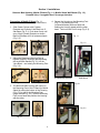
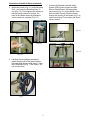
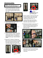
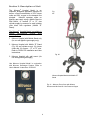
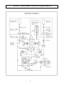
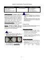
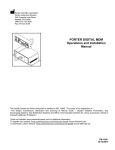
NITRONOX
USER’S MANUAL / INSTRUCTIONS
1 0 1 1 5 9 0 0 R e v. L 0 2 / 1 3
www.porterinstrument.com/nitronox
Nitronox® Hospital Model Inhalation Analgesia Machine - Serial Number:
Table of Contents
Examination ............................................................................................................ 1
Warnings and Precautions ...................................................................................... 2
New or Modified Installations .................................................................................. 3
Self-Administration vs. Assist to Self-Administration .............................................. 3
Installations: Preparation of Mobile E-Stand ........................................................... 4
Installations: Preparation of Nitronox Scavenger Parts .......................................... 6
Installations: Attachment of Cylinders ..................................................................... 7
Description .............................................................................................................. 8
Functional Schematic .............................................................................................. 9
Specifications / Functional Features ....................................................................... 10
Functional Warnings and Cautions ......................................................................... 10
Functional Tests ...................................................................................................... 10
Operation / Maintenance......................................................................................... 11
Troubleshooting ...................................................................................................... 14
Warranty ................................................................................................................. 15
Examination
Examine shipping carton for signs of external damage.
Remove contents from carton and inspect for visible damage or missing parts.
If damage is discovered or suspected and/or parts are missing, notify Porter or authorized
distributor immediately.
1
IMPORTANT:
READ MANUAL COMPLETELY BE F O R E O P E R A T I N G T H I S D E V I C E
Basic delivery technique is described. Also, this manual contains instructions on periodically
required checks to be performed by the user. These checks are necessary to insure the proper
performance of this device and its safety features. Retain this manual for future reference.
WARNINGS AND PRECAUTIONS
These warnings and precautions are to help
you to understand how to safely operate the
Nitronox device. A WARNING alerts you to a
possible hazard to people. A CAUTION alerts
you to the possibility of equipment damage.
low levels of ppm (parts per million) exposure.
Contact Porter or Authorized Distributor for
details on monitors and testing.
Inspect and maintain the analgesia delivery
system to prevent N2O leaks in all hoses,
connections and fittings. Have all leaks
repaired immediately.
WARNING: New or modified installations properly connected gas pipelines are
absolutely essential to patient safety. The
ultimate responsibility of assuring that lines
are not crossed rests with the user. See
next page for details.
WARNING: Medical workers are exposed to
N2O during administration of N2O/O2 conscious
sedation analgesia. NIOSH has recommended
that exposures should be minimized. Contact
NIOSH (1-800-35-NIOSH) to receive NIOSH
Publications on Control of Nitrous Oxide in
Dental Operatories.
Exposure can be
minimized by effective controls.
National
Institute for Occupational Safety and Health
(NIOSH) publications state that controls,
including System Maintenance, Ventilation and
Work Practices can effectively reduce N2O
concentrations in patient procedures. Your
accessory Porter scavenger system is an
important part of the system of controls in
medical settings.
WARNING:
Porter Instrument equipment
utilizes the cross+protection system. The
flexible hose and connectors that connect to
the housing are diameter indexed; 3/8” O.D. for
Nitrous Oxide and ½” O.D. for Oxygen. The
cross+protection system is designed to
prevent misconnection of Oxygen and Nitrous
Oxide hoses.
DO NOT ATTEMPT TO
CHANGE
THE
DIAMETERS
OR
CONNECTORS OF THE DEVICE! Tampering
with the cross+protection system constitutes
acceptance of liability by the installer.
CAUTION: Always use clean, dry medical
grade gases. Introduction of moisture or other
contaminants into this device may result in
defective operation.
WARNING: Nitronox® Analgesia units are
intended to be used by medical personnel
trained in its use and the use of nitrous oxide
and oxygen for medical applications.
CAUTION: Do not attempt to repair, alter or
calibrate this device. Unauthorized repair,
alteration or misuse of this device is likely to
adversely affect the performance and will void
the warranty.
WARNING: Do not use this device for the
administration of general anesthesia or as a
part of, or in conjunction with, a general
anesthesia administration system.
WARNING: Use Scavenging
CAUTION: Never oil or grease any part of this
system (minimize fire or explosion potential).
Monitor for N2O in the patient treatment area
to insure that controls are effective in achieving
2
WARNING:
NEW OR MODIFIED INSTALLATIONS
ALWAYS ASSURE THAT LINES ARE NOT CROSSED!
WARNING: New or modified central supply installations - properly connected gas pipelines are
absolutely essential to patient safety. The authorized distributor or contractor should provide written
documentation that all gas pipelines are connected properly and that the system has been pressure tested
prior to use. While this is a good business practice, it is important that the user verify by their own test,
independent of the authorized distributor or contractor, that all gas pipelines are connected correctly prior to
using the system. The ultimate responsibility of assuring that lines are not crossed rests with the
user.
Do not allow crossed lines to defeat the safety features of the Nitronox and/or central
gas supply manifold systems. Crossed lines will create a dangerous and hazardous condition
where, under a loss of oxygen supply, 100% nitrous oxide will be delivered through the oxygen
delivery path and subsequently to the patient.
Maintain patient observation during procedures. Prevent over sedation. If a patient becomes over
sedated when being delivered 100% oxygen [during an apparent loss of nitrous oxide supply], it is a
definite indication of crossed lines. If crossed lines are suspected, remove the mask immediately
and encourage mouth breathing. Deliver pure oxygen from an oxygen demand valve only if the
oxygen source is independent from the suspected crossed lines area.
INPUT PRESSURE DIFFERENCES
WARNING: Oxygen input pressure more than 15 psi higher than Nitrous Oxide input pressure will
cause low oxygen percentage mixture delivery. DO NOT use Nitronox if O2 input exceeds N2O input
by 15 psi or higher.
SELF-ADMINISTRATION VS. ASSIST TO SELF-ADMINISTRATION
WARNING: Encourage patient to self-administer. Self-administration is a safety feature of the
demand flow Nitronox in that, if for any reason the patient becomes over sedated, the patient will be
unable to successfully hold the mask in a tight seal position on the face. The result will be that the
mask falls away from the face and the demand flow will cease, allowing the patient to breathe room
air in through the mouth or nose.
WARNING: If a patient is unable to fully self-administer, and the medical professional provides an
assist to placement of the mask in a sealing position on the face, maintain patient observation to
prevent over sedation under any conditions. Discontinue the assistance in mask placement
immediately upon any observation of over sedation; remove the mask from the face entirely. Never
use a mask strap to hold the mask to the face. Never force the mask on the face; the patient must
always be spontaneously breathing.
As an added precaution for procedures where an assist to self-administration is used, continuously
sample the mixture delivery downstream from the demand valve by installation of an oxygen
analyzer.
3
Section 1: Installations
Nitronox Main Housing, Mobile E-Stand (Fig. 1.1), Mobile Stand, Wall Mount (Fig. 1.2),
Demand Valve, Corrugated Hose, Scavenger Interface
Preparation of Mobile E-Stand Fig. 1.1
Also see FM-916 E-Stand User’s Instructions
1. Slide Center Column with Cylinder
Restraint and Cylinder Yoke Block into 5Star Base (Fig. 2.1). Push down firmly until
snug. Align Cylinder Restraint as shown.
Base of cylinders will fit in between wheels
(Fig. 2.2).
4. Secure the Housing on the Mounting Post
(Fig. 5.1) by twisting the Post
(counterclockwise) with one hand and
holding the Housing steady with the other
hand. Twist until the Post is snug (Fig. 5.2).
Fig. 1.1
Fig. 1.2
Fig. 2.1
Fig. 2.2
2. Adjust the Recessed Mounting Post to
highest height by loosening and tightening
the small black handle (Fig. 3.1) on the
Yoke Block – and raising the Mounting Post
(Fig. 3.2).
E-Stand with Nitronox
Fig. 3.1
Fig. 3.2
3. The Nitronox Main Housing will mount on
the Mounting Post of the E-Stand [or Mobile
Stand] by sitting the bottom of the Housing
(Fig. 4.1) on top of the Mounting Post
(larger threads Fig. 4.2). Hold the Mounting
Post in one hand and position the Housing
with the other.
Wall Mount
Fig. 5.1
Fig. 5.2
Fig. 4.1
Fig. 4.2
4
Preparation of Mobile E-Stand (continued)
5. Attach the Handle (Fig. 6.1) to the Mounting
Post – just under the Retaining Ring / Oring (Fig. 6.2). Firmly tighten both screws so
that the Handle cannot be twisted. The
back of the Handle should be positioned
over the back two cylinders (Fig. 6.3).
7. Connect the Diameter Indexed Safety
System (DISS) green Oxygen and blue
Nitrous Oxide Hoses to the appropriate
connections (Fig. 8.1) on the bottom of the
Nitronox Main Housing. Slide the Hoses
through the opening in the Handle (Fig. 8.2)
before connecting. Firmly tighten the Hoses
using a wrench.
Fig. 8.1
Fig. 6.1
Fig. 6.3
Fig. 8.2
Fig. 6.2
6. Carefully clip the [shipping accessory]
plastic fasteners off of the green Oxygen
Hose and blue Nitrous Oxide Hose – under
the E-Stand Block (Fig. 7). Be careful – do
not cut the Hoses.
Fig. 7
5
Preparation of Nitronox Scavenger Parts
For further details, refer to Nitronox Scavenger
User’s Manual 10152100
8. Connect the Demand Valve (Fig. 9.1) to the
black Gas Delivery Hose (connected
through underside of Nitronox Main
Housing Fig. 9.2). This is a quick connect
attachment. Push the two ends together
until click sound is heard (Fig. 9.3). To
remove – push the metal clip in – and pull
apart.
10. Follow instructions FM-1236 included with
19mm Magenta Hose: Part number
92120041 – 19mm Corrugated Scavenger
Hose Assembly Instructions. (Figs. 11.1,
11.2, Fig. 12)
Fig. 11.1
Fig. 11.2
Fig. 12
Fig. 9.1
Fig. 9.2
Fig. 9.3
9. The bracket and clip on the side of the
Housing (Fig. 10.1) may be used to hold
the Demand Valve assembly and Hoses
when not in use (Fig. 10.2).
Fig. 10.1
Nitronox Scavenger on Housing
11. Attach the Nitronox Scavenger Interface to
the Center Column (Figs. 13.1, 13.2).
Fig. 13.1
Fig. 10.2
6
Fig. 13.2
Attachment of Cylinders
Caution: When operating the swivel yoke,
take care not to catch or pinch fingers.
12. Loosen the Tee Handle (Fig. 14.1) until
point is even with the inside of the Swivel
Arm. Push Tee Handle inwards to flip to
open position. Align Tee Handle vertically
(Fig. 14.2).
Fig. 16.4
O2 Pins
Fig. 16.3
Warning
Do not remove or alter
gas indexing pins
16. Slide the cylinder into place by lining up the
pins and pin holes on the cylinder. Push
into place. Properly placed, the cylinder
should hang on the pins (Fig. 17).
Fig. 14.2
Fig. 14.1
13. Undo the Hook & Loop straps on the
Cylinder Restraint (Fig. 15)
17. Cylinders should hang freely between
wheel base. If the wheel base interferes,
loosen and rotate cylinder restraint.
18. Rotate swivel clockwise to close (Fig. 18.1).
Swivel will move into the locked position
when Tee Handle is tightened. Secure the
Hook & Loop straps to hold cylinder in
place (Fig. 18.2).
Fig. 15
14. Cylinder Preparation: Remove any plastic
wrap from the top of cylinder, including the
cylinder plastic washer. Verify that the
rubber washer (Fig. 16.2) provided with the
E-Stand is still in place. Use the E-Stand
washer.
Fig. 17
Fig. 18.1
15. Mount the “E” cylinders of Oxygen and
Nitrous Oxide (not included) to the E-Stand
Block. Insert cylinders correctly on indexing
pins and as marked on Block (N2O Figs.
16.1, 16.2; O2 Figs. 16.3, 16.4). Pins assure
mounting in appropriate position.
Fig. 18.2
Fig. 19
19. The Cylinder Valve Wrench (hanging from
black Knob) is used to open/close Cylinder
Valves (Fig. 19). See FM-916 User’s
Instructions.
N2O Pins
Fig. 16.1
Fig. 16.2
Rubber
Washer
7
Section 2: Description of Unit
Fig. 21
The Nitronox® Hospital Model is an
inhalation analgesia apparatus designed to
deliver a fixed concentration of 50% nitrous
oxide and 50% oxygen on the demand flow
principle.
Nitronox operates either on
pipeline gas supply using a Mobile Stand or
Wall Mount, or medical “E” or “D” size
cylinder supply by means of a small cylinder
yoke block with regulators (Mobile “E”
Stand).
Fig.
20 -
The Nitronox® Hospital Model is available in
various
configurations
offering
three
mounting styles.
1. Nitronox Hospital with Mobile Stand only
(for use with pipeline gas supply only).
2. Nitronox Hospital with Mobile “E” Stand
(Fig. 20) and cylinder mount- (2) nitrous
oxide and (2) oxygen – “E” or ”D” size.
Refer to FM-916 for Installation and User
Instructions.
Fig. 20
3. Nitronox Hospital with wall mount (for
use with pipeline gas supply)
Use Nitronox Hospital Model in conjunction
with Nitronox Scavenger System; Refer to
User’s Manual / Instructions 10152100.
Nitronox Hospital Model with Mobile “E”
Stand
Fig. 21 – Nitronox Front Cover with Mixture
Pressure and N2O and O2 Line Pressure Gages
8
Nitronox ® Hospital Model Inhalation Analgesia Machine
9
Section 3: Specifications / Functional Features
Gas Supply Duration
“E” Size Cylinders At Normal
Breathing Rates:
N2O Approximately 6 – 6.5 Hrs.
O2 Approximately 2 – 2.5 Hrs.
Flow Capability
114 LPM, Maximum
Oxygen Fail Safe: If apparatus oxygen line
pressure is depleted or disconnected, nitrous oxide
flow and demand valve flow stops automatically. If
apparatus nitrous oxide line pressure is depleted or
disconnected, demand valve will continue to
function providing 100% oxygen at reduced flow
capacity of about 55 LPM. If patient takes abnormal
shallow breaths (100 to 200 cc tidal volume),
oxygen concentration automatically increases.
Mixture Concentration
Mixture Concentration
(Factory Adjusted)
50% N2O and 50% O2
+/- 5 Percentage Points O2
Warnings
•
If WHISTLE ALARM sounds, discontinue
patient use immediately and shut off gas
supply.
•
WARNING: DO NOT use Nitronox if O2 input
exceeds N2O input by 15 psi or higher [see
Warnings page 3]
Mixer Pressure Alarm: A whistle will sound
when a gas mixture regulator seat malfunction
affecting mixture concentration has occurred.
Warning:
Nitronox® Analgesia units are
intended to be used by medical personnel
trained in its use and the use of nitrous oxide
and oxygen for medical applications.
Functional Tests
Prior to first use and periodically thereafter (monthly
is suggested), perform the following tests:
Whistle Alarm Actuation:
1. Increase mixture pressure per Page 7, Step 2,
“Maintenance”, until gauge reading is in RED
“Do Not Use” area, per gauge illustration.
Warnings
•
DO NOT use Nitronox if either line or
mixture pressure is out of green band (see
“Maintenance”). Figs. 22.1, 22.2
2. WHISTLE should sound in this range.
3. If WHISTLE sounds before or after this range,
WHISTLE ALARM ACTUATOR must be
adjusted (see “Maintenance”).
Fail Safe Check-Out Test:
Fig. 22.1
•
Fig. 22.2
Encourage patient to self administer at all
times [see Warnings page 3 for details].
10
1. With unit in operation (one each O2&N2O gas
supplies on), turn off or disconnect oxygen at
supply source.
2. As oxygen pressure falls to zero (as read on
oxygen line pressure gauge), demand valve
flow
must
stop
completely.
Section 4: Operation / Maintenance
Cylinder Pressure Readings: Oxygen is a true
compressed gas, while in the cylinder, thus the
cylinder pressure gauge can be used to determine
the amount of gas remaining in the cylinder. For
example, 2000 psi indicates full, 1000 psi indicates
half full, etc. Nitrous Oxide is a liquefied
compressed gas that vaporizes in the cylinder, thus
the cylinder pressure gauge cannot be used to
determine the amount of gas remaining in the
cylinder until all liquid in the cylinder vaporizes.
While liquid remains in the cylinder, the cylinder
pressure gauge indicates the vapor pressure which
depends on and varies with the temperature of the
liquid. For example, at 68ºF, the vapor pressure is
about 750 psi; at 20ºF, it drops to about 400 psi;
while at 90ºF, it increases to about 1000 psi. After
all the liquid vaporizes, the pressure will decrease
normally as the gas is withdrawn, and the cylinder
pressure gauge can then be used to determine the
amount of gas remaining in the cylinder.
3. Minimize leak risks: With cylinder in position,
rotate swivel arm and move into secure locked
position when Tee Handle is tightened. To
prevent movement and potential damage to
yoke pins, always fasten the Hook & Loop strap
restraints around cylinders.
4. Assure “E” Stand is populated with at least one
full cylinder of O2 and N2O before starting any
procedure.
5. Label each cylinder with a tag or sticker
indicating “In-Use” and “Full” (“Full” is reserve
cylinder.)
6. Use Cylinder Valve Wrench to open the “InUse” cylinders of O2 and N2O. Verify wrench is
attached to Block.
7. Cylinder pressure gages on Block provide a
visual indication of cylinder status (see details
on Cylinder Pressure Readings)
Cautions
•
Always turn on CYLINDER VALVES slowly
and fully (“E” cylinder yoke models).
•
Hex hole in cylinder valve wrench to be
used only to tighten cylinder valve packing
nut in event of a leak.
8. Caution: If all four cylinders (or both cylinders
of one gas) are open, the two cylinders of O2
and N2O will deplete in tandem. The “Full”
cylinder will empty with the “In-Use” cylinder
and will not be available as a future spare.
•
NEVER ATTEMPT TO LOOSEN cylinder
valve packing nut. If valve stem is tight,
return cylinder to supplier.
9. When “In-Use” cylinder is depleted, open the
spare “Full” cylinder (Close valve on empty
cylinder).
Warning: Do not remove or alter gas
indexing pins
10. When “In-Use” O2 cylinder is depleted, the
Oxygen Fail Safe will stop N2O flow and
demand valve flow automatically.
Good practices: Cylinders with “E” Stand
1. Two cylinders of O2 and two cylinders of N2O
are typically connected at all times. Exception:
When using external gas supply of oxygen, the
“E” Stand may be populated with N2O cylinders
and O2 cylinders are not placed on “E” Stand.
2. Minimize leak risks: Confirm Yoke Washers are
in place before replacing/mounting cylinders.
Use Porter #A-3399-000 replacement washers
(once/yr.). Have spare washers.
11
11. When “In-Use” N2O cylinder is depleted, the
Nitronox will deliver 100% O2 through the
Demand Valve.
12. After use, turn off cylinder valves. Caution:
With O2 cylinder turned on, the Nitronox will
have an intentional small O2 bleed, which will
tend to deplete the O2 cylinder if, after use, the
O2 cylinder valve is left on.
Models With “E” Cylinder Yoke (Simple
Operation Procedure)
1. Open one each O2 and N2O Cylinder Valves
with wrench provided.
2. Observe cylinder pressures. Replace cylinder
when less than 300 psi, at room temperature
(21.1 ºC, 70ºF). During replacement, close all
Cylinder Valves.
Fig. 23.1
3. Observe line pressures (Fig. 23.1). Normal is
50-55 psi (green band) for static no-flow
condition. Pressure will decrease slightly during
each inspiration (see “Maintenance”).
4. Observe mixture pressure (Fig. 23.2). Normal is
30-35 psi (green band) for static no-flow
condition. Pressure will decrease slightly during
each inspiration (see “Maintenance”).
5. If all pressures are normal, Nitronox is ready to
use. Remove Demand Valve with Mask from
storage bracket. Instruct patient to hold Mask
lightly on face covering nose and mouth.
Instruct to breathe normally, preferably through
nose.
Encourage patient to self administer at all
times [see Warnings page 3 for details].
6. After use, turn off Cylinder Valves; store
Demand Valve with Mask and Hose.
Models Using Pipeline or External Gas
Supply (Mobile Stand or Wall Mt.)
1. Connect external gas supply hoses to DISS
(Diameter Indexed Safety System) fittings.
External pressure must be 40-65 psi, preferably
50-55 psi. Observe external pressures on
apparatus LINE PRESSURE GAUGES.
WARNING: DO NOT use Nitronox if O2 input
exceeds N2O input by 15 psi or higher.
2. Observe mixture pressure as in step 4 above.
3. Follow step 5 procedure above.
4. After use, disconnect external gas supply.
12
Fig. 23.2
Maintenance
1. Line Pressure Adjustment: (Green Band
for Model Using Mobile “E” Stand): Locate
appropriate PRESSURE REGULATOR (blue
lettering – nitrous oxide; green lettering –
oxygen); remove 9/16” acorn nut; insert 5/32”
hex socket key and adjust pressure to within
green band.
2. Mixture Pressure Control Adjustment:
(Green Band): Remove LOWER CHROME
PLUG from case back. With wrench, loosen
7/16 inch hex nut (counterclockwise)
approximately one quarter turn. Insert
screwdriver through access hole, in bottom of
case, into slot of adjusting screw. While holding
nut with wrench, adjust counterclockwise to
increase pressure – clockwise to decrease.
After adjustment, tighten nut while holding
screw in position with screwdriver (see
illustration Fig. 24).
3.
Leak Test System – Monthly Check of
working pressure leaks. Verify hoses are
attached from E-Stand to Nitronox Housing.
Turn one O2 and one N2O cylinder on. Verify EStand pressure gages read cylinder pressures.
Verify Nitronox line pressure gages read within
green band. Note: fail safe is open and
pressure reaches Demand Valve. Turn off N2O
cylinder valve. Verify that N2O E-Stand gage
reads about 750 psi. Note exact needle
position. Verify that there is little or no
movement [up to ½ increment] of the exact
needle position in 15 minutes. Nitronox N2O
line pressure gage needle will stay in green
band with no movement. Turn off O2 cylinder
valve. It is normal that needle of O2 E-Stand
gage will drop. Nitronox O2 line pressure gage
needle will stay in green band with no
movement (will eventually drop after E-Stand
gage pressure naturally depletes).
13
4. Whistle Alarm Actuator
Adjustment:Remove UPPER CHROME
PLUG from case back. With mixture pressure
temporarily adjusted in middle of range shown
below (per Step 2, “Maintenance”), insert 1/8”
hex key (not provided) into adjustment screw at
end of ALARM ACTUATOR (see illustration Fig.
2). Adjust screw either clockwise or
counterclockwise until whistle sounds clearly.
DO NOT over adjust. Return mixture pressure
to middle of green band. Whistle sound must
stop with pressure in green band and whistle
must sound with pressure in range shown
below (about 40 psi). If this cannot be achieved,
discontinue use of apparatus and notify
authorized distributor immediately (see
illustration Fig. 25).
5. Replacing the Check Valve
See FM-916 “E” Stand for illustrations and
instructions for replacement of the Check Valve
Assembly.
Fig. 24
Fig. 25
Section 5: Troubleshooting
Field repair is limited to maintenance adjustments and replacement parts obtained
through Porter. All other repairs should be performed by an authorized Porter service
representative.
PROBLEM
POSSIBLE CAUSE
CORRECTIVE ACTION
1.
L e a k ag e a t YO K E
C YLI ND ER VAL VE
c o n n e ct i o n.
Missing or defective yoke seal
w a s her ( mo de l s w it h “ E”
c y l i n d er y o ke) ; d am a ge d pin s .
R e p la c e w i th P or t er p ar t N o .
A - 33 9 9- 0 0 0 ( 4 p er U n i t) .
2.
L o w or n o r ea d i n g o n
C YLIND ER GAUG E w ith
CYLINDER VALVES open.
C y l i n de r pr e ss u r e t oo l ow o r
c y l i n d er s emp t y ( mo d e l s w i t h
“ E” cyl i nd er yo ke ).
R e p la c e c y l in d er w i th f u l l
c y l i n d er of ap p r o pr i at e g as .
3.
O 2 c y l i nd er ( o r e x t er n a l
s u p p l y) u se d t o o q u i c k l y
O 2 c y l i nd er va l v e ( or e x t er n a l
s u p p l y) l ef t on a ft er u se an d
n a t ur a l b l ee d d e p le t e s c y l in d er
( or e x t er na l s u p p l y) .
O 2 c y l i nd er co n t a in s up to 2 . 5
h r s. br ea t h ing su pp ly; N 2 O
c y l i n d er c on ta i n s up to 6.5 hr s .
A p p ar at u s e xp o s e d t o
t e m per a tu r e b e l ow 32 º F / 0 º C .
U s e pr a c t i c e o f tu r n i n g o ff
c y l i n d er ( or ext e r n a l su p p ly )
a f t er u s e .
4.
5.
6.
L i n e p r e s s ur e o ut of gr een
b a n d.
M ixt ur e pr e ssu r e s o ut of
g r ee n b a nd .
WHISTLE ALARM failure
d u r in g f u n ct io n a l t e s t.
7 . WHISTLE ALARM sound
N o te : a mo me n t ar y “ ch i r p”
s o u n d i s a c ce p t ab l e u p on
initial application of pressure if
w h i s t le th e n s t o p s [ r e s e ats]
E x p e c t h i g her u s a g e o f O 2
c y l i n d er s
Allo w a p par at u s to r e tur n t o
r o om t e mp era t ur e b e for e
m a k i n g a d ju st m e nt .
PRESSURE REGULATOR out
o f ad j u stm e nt ( m od e l s w i th “ E”
cylinder yoke) .
S e e “ M a i n te na n c e” ad j u s tm e n t,
Step 1.
P R E S SURE REG UL AT O R
d e f e ct i v e ( mo d e l s w i th “ E”
cylinder yoke) .
D i s c o nt i n ue u s e an d n o t ify
a u t ho r i ze d d is t r i bu t or .
CO NTRO LLED PR ESSURE
REGULATOR section of
m i x t ur e r e q u ir e s a d j u st men t
S e e “ M a i n te na n c e” ad j u s tm e n t,
Step 2.
R EG U L AT O R m a l fu n c t io n
( mo d e l s w it h “ E” c y l i nd er
yoke).
A L A R M ACT U ATO R o ut of
a d j u s tm e nt .
D i s c o nt i n ue u s e an d n o t ify
a u t ho r i ze d d is t r i bu t or .
A C T U A T O R D EF EC T I V E
L e a k a t N 2 O p r e s sur e co nt r o l
s e a t ca u s i ng l o w O 2
c o n c e nt r a t i on .
A C T U A T O R D EF EC T I V E.
14
S e e “ M a i n te na n c e” ad j u s tm e n t,
Step 3.
D i s c o nt i n ue u s e an d n o t ify
a u t ho r i ze d d is t r i bu t or .
D i s c o nt i n ue u s e an d n o t ify
a u t ho r i ze d d is t r i bu t or .
CERTIFICATE OF WARRANTY
THIS WARRANTY IS GIVEN IN PLACE OF ALL OTHER WARRANTIES,
EXPRESS
OR
IMPLIED,
OF
MERCHANTABILITY,
FITNESS
FOR
A
PARTICULAR PURPOSE OR OTHERWISE.
Under no circumstances shall Parker Hannifin Corporation be liable for incidental or consequential
damages as those terms are defined in the uniform commercial code.
Parker Hannifin Corporation, Porter Instrument Division warrants that each product or part shall be
free from defects in workmanship and materials, under normal use and with appropriate maintenance,
for one (1) year from the date of delivery to customer unless otherwise specified in writing. All rubber
and plastic parts and accessories are warranted under the same conditions for a period of ninety (90)
days from date of purchase.
No statement or claim about the product by any employee, agent, representative, or dealer of Parker
Hannifin Corporation shall constitute a warranty by Parker Hannifin Corporation or give to rise to any
liability or obligation of Parker Hannifin Corporation.
Parker Hannifin Corporation shall not be liable for any damage, injury or loss arising out of the use of
the product, whether as a result of a defect in the product or otherwise, if, prior to such damage, injury
or loss, the product was (1) damaged or misused; (2) repaired, altered or modified by persons other
than Parker Hannifin Corporation; (3) not installed in strict compliance with applicable codes and
ordinances; or (4) not installed by an authorized Parker Hannifin Corporation dealer. Parker Hannifin
Corporation's obligation for breach of this warranty, or for negligence or otherwise, shall be strictly and
exclusively limited to the repair or replacement of the product or part. This warranty shall be void on
any product on which the serial number has been altered, defaced or removed.
ORDERS All orders are to be made through authorized Parker Hannifin Corporation distributors. All
billing will be done through said distributors. Direct orders will be handled through the authorized local
dealer as determined by Parker Hannifin Corporation.
RETURNS All returned merchandise will be handled through the local Parker Hannifin Corporation
distributor. No returns will be accepted unless authorized in writing by Parker Hannifin Corporation
and accompanied by the original shipping invoice. All returns are subject to restocking charge.
Policies subject to change without notice.
T he Q ua lity Sys te m fo r Por ter Ins tr umen t is cer tified to ISO 134 85 . T he sco pe o f
o ur r eg is tr a t io n is : Th e des ig n, m a nu fac tu r e , dis tr i bu t io n and s e r vic in g of N i tr ous
O xid e - O xyg en Se da tion F low Me ters , Gas Sca veng ing Sys tems , Ste am Ster iliz ers ,
G as D is t r i bu t io n an d O f f ic e C omm un ica t io n S y s te ms fo r use b y a ph ys ici an , den t is t
o r l ic e nsed h ea l thc a r e pr o fess io na l .
15