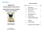
1
DIGITAL MXR-D FLOWMETER USER’S MANUAL Instructions and Safety Considerations Cabinet Mount MXR-D Porter Conscious Sedation Flowmeter and Bag Tee (Accessory) FM-1061 Rev. B 4/11 IMPORTANT: READ MANUAL COMPLETELY BE F O R E O P E R A T I N G T H I S D E V I C E Basic delivery technique is described. Also, this manual contains instructions on periodically required checks to be performed by the user. These checks are necessary to insure the proper performance of this device and its safety features. Retain this manual for future reference. CAUTION: Federal law U.S. restricts this device for use by or on the order of a physician, dentist or licensed practitioner. Date Purchased: MXR-D Model No.: 4065D Serial Number: Dealer Name: Dealer Phone No.: UL Classified to 60601-1: Medical Equipment with respect to electric shock, fire and mechanical hazard only in accordance with UL 60601-1 and CAN/CSA C22.2 No. 601.1-M90. Symbol Description Protective Earth Ground, Class I Device Alternating Current Attention, consult the accompanying documents. Type B Equipment • • Distribution of Porter Model 4065D is limited and controlled to United States and Canada only. The Porter Model 4065D incorporates fusing only in the ungrounded phase conductor. This product must not be used in countries other than the United States and Canada and must be used only in health care facilities on grounded systems where conditions of maintenance and supervision ensure that only qualified persons will service the electrical distribution system. For Technical Assistance, contact Dental Customer Service: Parker Hannifin Corporation Porter Instrument Division 245 Township Line Road Hatfield, PA 19440 USA Phone: 215-723-4000 Fax: 215-723-5106 Internet: www.porterinstrument.com 2 Table of Contents WARNINGS AND PRECAUTIONS................................................................................................ 4 CROSSED LINES WARNING......................................................................................................... 5 Do Not Allow Crossed Lines to Defeat Equipment Safety Features.......................................... 6 NITROUS OXIDE CONSCIOUS SEDATION SYSTEM ILLUSTRATION ................................. 7 NITROUS OXIDE CONSCIOUS SEDATION SYSTEM COMPONENTS & ACCESSORIES ... 8 SAFETY: ........................................................................................................................................... 9 ADA Guidelines............................................................................................................................. 9 NFPA Codes .................................................................................................................................. 9 GAS SUPPLY CONNECTION..................................................................................................... 9 TANK REGULATOR SPECIFICATIONS ...................................................................................... 9 Oxygen Regulator .......................................................................................................................... 9 Nitrous Oxide Regulator ................................................................................................................ 9 INTENDED USE—Flowmeter for Analgesia Delivery System ..................................................... 10 USE SCAVENGING ................................................................................................................... 10 MONTHLY LEAK CHECK ....................................................................................................... 10 SWITCHABLE CONNECTORS .................................................................................................... 10 DIGITAL MXR-D FLOWMETER FEATURES............................................................................ 11 DIRECTIONS FOR USE ................................................................................................................ 12 Basic Delivery Technique............................................................................................................ 13 MAINTENANCE AND SERVICE................................................................................................. 13 CLEANING METHODS................................................................................................................. 13 DIGITAL DISPLAY READOUTS ................................................................................................. 14 INITIALIZATION PROCEDURE.................................................................................................. 15 NITROUS AND OXYGEN FLOW TUBE INDICATORS............................................................ 16 USAGE DURING POWER OUTAGE ....................................................................................... 16 FLOWMETER ACCESSORIES ..................................................................................................... 17 Three or Two Liter Reservoir Bag............................................................................................... 17 Positive Pressure / Demand Valve............................................................................................... 17 Gas Scavenger Breathing Circuit................................................................................................. 17 Automatic Vacuum Switch [AVS] (Option)................................................................................ 18 In-line Vacuum Control Kit (Option) ......................................................................................... 18 BAG TEE......................................................................................................................................... 19 Non-Rebreathing Valve—Check Monthly .................................................................................. 19 Emergency Air Valve—Check Monthly ..................................................................................... 19 SAFETY FEATURE CHECKS....................................................................................................... 20 Low Oxygen Detection ................................................................................................................ 20 High Nitrous Percentage Detection ............................................................................................. 20 Nitrous Oxide Failsafe System—Check Before Each Use .......................................................... 21 Power Oxygen Flush—Check Monthly [Mechanical Check] ..................................................... 22 Quick Test to Check Reservoir Bag / Rubber Goods for Leaks .................................................. 22 MONTHLY CALIBRATION CHECK........................................................................................... 23 TECHNICAL SPECIFICATIONS .................................................................................................. 24 UL CLASSIFICATION............................................................................................................... 24 Performance and Accuracy .......................................................................................................... 25 TROUBLESHOOTING CHART FOR MXR FLOWMETERS ..................................................... 26 PARTIAL LISTING OF REFERENCE MATERIAL .................................................................... 27 CERTIFICATE OF WARRANTY.................................................................................................. 28 3 WARNINGS AND PRECAUTIONS These warnings and precautions are to help you to understand how to safely operate the MXR Flowmeter. A WARNING alerts you to a possible hazard to people. A CAUTION alerts you to the possibility of equipment damage. WARNING: Do not use this device for the administration of general anesthesia or as a part of, or in conjunction with, a general anesthesia administration system. WARNING: Dental workers are exposed to N2O during administration of N2O/O2 conscious sedation analgesia. NIOSH has recommended that exposures should be minimized. Contact NIOSH (1-800-35NIOSH) to receive NIOSH Publications on Control of Nitrous Oxide in Dental Operatories. Exposure can be minimized by effective controls. National Institute for Occupational Safety and Health (NIOSH) publications state that controls, including System Maintenance, Ventilation and Work Practices can effectively reduce N2O concentrations in dental operations. Your flowmeter accessory Porter scavenger system is an important part of the system of controls. WARNING: Porter Instrument equipment utilizes the cross+protection system. The flexible hose and connectors that connect to the flowmeter are diameter indexed; 3/8” O.D. for Nitrous Oxide and ½” for Oxygen. The cross+protection system is designed to prevent misconnection of Oxygen and Nitrous Oxide piping. DO NOT ATTEMPT TO CHANGE THE DIAMETERS OR CONNECTORS OF THE FLOWMETER! Tampering with the cross+protection system constitutes acceptance of liability by the installer. For your own protection, as well as that of the Doctor and the patients, use 3/8” O.D. tubing for all Nitrous Oxide lines and ½” O.D. tubing for all Oxygen lines. To assure safe operation and conformation to local fire codes, all Porter Instrument flowmeter systems are designed to be used with sedation delivery systems mounted inside walls and they meet or exceed the guidelines established by the National Fire Protection Association for Nonflammable Medical Gas Systems, NFPA 99. Copies of NFPA 99 or portions thereof may be obtained by writing to: National Fire Protection Association, Batterymarch Park, Quincy, MA 02269-9904; or call 1-800-344-3555 WARNING: New or modified installations - properly connected gas pipelines are absolutely essential to patient safety. The dealer or contractor should provide written documentation that all gas pipelines are connected properly and that the system has been pressure tested prior to use. While this is a good business practice, it is important that the user verify by their own test, independent of the dealer or contractor, that all gas pipelines are connected correctly prior to using the system. The ultimate responsibility of assuring that lines are not crossed rests with the user. WARNING: Do not use an electrical cord with nicks, cuts, or other damage. WARN ING: During any extended power outage, remember to turn the On / Standby (Off) switch to the ST ANDBY p osi tio n o n the fl owm e ter and manually turn OFF the tank valves. With centralized, electrically powered gas systems, if gas was flowing when the power went out and the flowmeter is left ON, gas will be flowing when the power is restored. CAUTION: Federal law (U.S.) restricts this device for use by or on the order of a physician, dentist or licensed practitioner. CAUTION: Always use clean, dry medical grade gases. Introduction of moisture or other contaminants into this device may result in defective operation. CAUTION: Do not attempt to repair, alter or calibrate this device. Unauthorized repair, alteration or misuse of this device is likely to adversely affect the performance and will void the warranty. CAUTION: Never oil or grease any part of this system (minimize fire or explosion potential). CAUTION: There are no user-serviceable parts inside this unit. A shock hazard exists if power is not disconnected prior to any internal servicing or maintenance. Always disconnect the power source before inspection or repair. CAUTION: Do not change any internal factory set adjustments. The Porter Digital MXR is adjusted and calibrated for proper operation prior to shipment. Any change could alter the specified operation and accuracy. 4 CROSSED LINES WARNING NEW OR MODIFIED INSTALLATIONS ALWAYS ASSURE THAT LINES ARE NOT CROSSED! WARNING: New or modified installations - properly connected gas pipelines are absolutely essential to patient safety. The dealer or contractor should provide written documentation that all gas pipelines are connected properly and that the system has been pressure tested prior to use. While this is a good business practice, it is important that the user verify by their own test, independent of the dealer or contractor, that all gas pipelines are connected correctly prior to using the system. The ultimate responsibility of assuring that lines are not crossed rests with the user. Do not allow crossed lines to defeat the safety features of the dental flowmeter and / or central gas supply manifold systems. Crossed lines will create a dangerous and hazardous condition where 100% Nitrous Oxide will be delivered through the Oxygen dental flowmeter tube and subsequently to the patient. In addition, the resuscitator quick connect would deliver 100% Nitrous Oxide to an Oxygen demand valve. Maintain patient observation during procedures. Prevent over sedation. If a patient becomes over sedated when being delivered 100% Oxygen, it is a definite indication of crossed lines. If crossed lines are suspected, remove the nasal mask immediately and encourage mouth breathing. Deliver pure Oxygen from an Oxygen demand valve only if the Oxygen source is independent from the suspected crossed lines area. To check for crossed lines of an installed Porter Vanguard (or Sentinel) Manifold System: 1. At the manifold system (in the tank room), start the check from an operating system with 50 PSI showing on both gauges and the indicator lights turned on – electrical operation and alarms needed for the Vanguard test. Then, turn off both Oxygen tanks and leave both Nitrous Oxide tanks on. (For the Sentinel, only one tank of each gas is on at a time. Turn off the one open Oxygen tank, leave on the one Nitrous Oxide tank, turn off the indicator lights – eliminates alarms during the Sentinel test.) 2. In the operatory, where the flowmeter is installed, flow 5 to 6 liters per minute of O2 only. Verify that the N2O flowmeter valve is in the off position and that there is no indicated flow of N2O - by observing the ball float resting at the bottom of the glass N2O flow tube. This action will bleed the Oxygen copper tubing lines (1/2” OD) from the manifold, through the office walls, to the flowmeter. Note: this action does not cause a quick bleed down, as there is a fair sized volume in the lines. O2 flow would be observed by the position of the ball float in the O2 flow tube for several minutes. 3. Rather than waiting for the O2 flow to decrease, go back to the manifold tank room and observe the O2 pressure gauge on the manifold (normally showing approximately 50 PSIG pressure). The line pressure should start to decrease, indicating bleeding of the O2 that is no longer being replenished by the tanks. On Vanguard systems, the alarm will beep at 40 PSIG, a switch will occur from one tank to the second tank at a timed interval (increasing the gauge back to 50 PSIG). The gauge then should eventually go down to zero. If the O2 pressure does not go down as described above, and remains at about 50 PSIG, it indicates a crossed lines condition. 4. If O2 pressure does not go down, proceed to the next crossed line determination check. Turn N2O tanks off in the manifold tank room and watch the N2O gauge. Given a crossed line condition, the N2O gauge will now go down (the Vanguard system will show a switching similar to step 2 above) — this shows the O2 valve of the flowmeter is bleeding the crossed N2O lines. The N2O gauge will go down to zero. 5 Do Not Allow Crossed Lines to Defeat Equipment Safety Features Crossed lines in wall structure piping creates hazard of 100% Nitrous Oxide delivery to nasal mask and Oxygen demand valve when Flowmeter is set for 100% Oxygen resulting in over sedation. Over Sedation 6 4 At gas outlet station, the common run of 1/2 inch pipe for Nitrous Oxide is incorrectly allowed to remain at the 1/2 inch size and is then falsely connected to the DISS 1/2 inch outlet station. Nitrous Oxide is fed into the Oxygen lines. 5 Dental flowmeter valve is set for 100% Oxygen only, but will deliver 100% Nitrous Oxide because of the crossed lines. 6 A patient will become over sedated and may appear to fall asleep when the flowmeter is set for 100% Oxygen. 7 An Oxygen demand valve connected to the resuscitator quick connect of the Flowmeter will also deliver 100% Nitrous Oxide because of the crossed lines. The init ia l installation potentia l problem: 1 2 3 DISS (Diameter Index Safety System) is modified at tank room wall when 3/8 inch Nitrous Oxide pipe is increased to 1/2 inch pipe size. Oxygen pipe remains at the normal 1/2 inch size. Both Nitrous Oxide and Oxygen piping is maintained at a common 1/2 inch size throughout the building walls leading to operatories. At gas outlet station, the Oxygen 1/2 inch pipe is incorrectly decreased down to the DISS 3/8 inch size reserved for Nitrous Oxide lines. Oxygen is fed into the Nitrous Oxide lines. 6 NITROUS OXIDE CONSCIOUS SEDATION SYSTEM ILLUSTRATION 7 NITROUS OXIDE CONSCIOUS SEDATION SYSTEM COMPONENTS & ACCESSORIES Item No. Part Number Description 1 2 4065D AVS-5000 MXR Flowmeter with Power Supply and Cable AVS 3 5501-RK Vacuum Block Kit 4 5155-1 Adult Rubber Gds (w/ Vacuum Block) 4A 5155-3 Adult Rubber Gds (no Vacuum Block) 5 P1407A Bag Tee 6 4100 3L Bag 7 A-2633-000 Adapter for Bag Tee 8 A-1679 Remote Bag Tee Adapter 9 B-2460-001 O2 Check Valve 9A B-2461-001 N2O Check Valve 10 8005 O2 Hose, Diss / Diss, 5 Ft 10A 8505 N2O Hose, Diss / Diss, 5 Ft 10B 80012 O2 Hose, Diss / Diss, 12 Ft 10C 85012 N2O Hose, Diss / Diss, 12 Ft 11 PA-450-1-002 O2 Hose, 12 Ft 11A PA-450-1-001 O2 Hose, 20 Ft A-2508-000 Kit, Rubber Gds Hook 12 Mounting Options for Bag Tee and AVS 13 2036-4 3 1/2" Wide Slide (not shown) 14 2036-2 5" Wide Slide (not shown) 15 2037-1 7" Wide Under Cabinet Mt (not shown) 8 TANK REGULATOR SPECIFICATIONS SAFETY: ADA Guidelines In addition to the fail-safe and other safety features found on most sedation machines, effective August 1976, the following specifications were added to those required for acceptance by the ADA Council on Dental Materials and Devices: 1. Emergency Air Valve; 2. Non-rebreathing Check Valve; and 3. Resuscitator Quick Connect. Oxygen Regulator Use Porter O2 Regulator part number 7000-2 or the Oxygen tank regulator should have the following specifications: In addition, the ADA Council requires that: 1. The gas storage and delivery system meet the recommendations of the National Fire Protection Association (NFPA).; 2. The system be installed by a competent supplier of gases and equipment. NFPA Codes To assure safe operation and conformation to local fire codes, Porter Instrument Nitrous Oxide Sedation Systems meet or exceed the guidelines established by the National Fire Protection Association for Nonflammable Medical Gas Systems, NFPA 99. Copies of NFPA 99 or portions thereof may be obtained by writing to National Fire Protection Association, Batterymarch Park, Quincy, MA 02269-9904 USA or call: 1800-344-3555 Regulator should be pre-set at 50 PSIG ± 2 PSIG (static) Inlet fitting per CGA 540 Outlet fitting per O2 DISS I0 micron filter on inlet Self-resetting safety relief valve pre-set to 100 ± 10 PSIG 0-4000 PSIG color coded pressure gage Maximum flow capacity of no less than 150 LPM Droop shall be a maximum change in regulated pressure of 8% from 0-150 LPM when supply is 2000 PSIG. Regulation of the supply pressure should not change by more than 4% of set pressure at a flow of 75 LPM. UL Listed Installation shall conform to local codes with respect to pressure relief. Nitrous Oxide Regulator Use Porter N2O Regulator part number 7500-2 or the Nitrous Oxide tank regulator should have the following specifications: GAS SUPPLY CONNECTION After installation of the flowmeter, connect the Nitrous Oxide and Oxygen supply lines to the Diameter Indexed Safety System (DISS) fittings located on the back of the flowmeter unit. It is important that the regulators for both gases be set to give pressures in the range of 50 PSIG ±2 PSIG. Confirm the absence of leaks at pressure connections on the unit. Bubbles will appear at leaking locations when a soap / water solution is used. This procedure is recommended each time a cylinder is changed. 9 Regulator should be pre-set at 50 PSIG ± 2 PSIG (static) Inlet fitting per CGA 326 Outlet fitting per N2O DISS I0 micron filter on inlet Self-resetting safety relief valve pre-set to 100 ± 10 PSIG 0-1500 PSIG color coded pressure gage Maximum flow capacity of no less than 100 LPM Droop shall be a maximum change in regulated pressure of 8% from 0-150 LPM when supply is 800 PSIG. Regulation of the supply pressure should not change by more than 4% of set pressure at a flow of 75 LPM. UL Listed Installation shall conform to local codes with respect to pressure relief. INTENDED USE—Flowmeter for Analgesia Delivery System This device is intended for patient (adult and pediatric) use by an attending physician or dentist properly trained in its use. Porter Instrument recommends the user be thoroughly familiar with the use of Nitrous Oxide - Oxygen Conscious Sedation for patient analgesia and be properly trained in its administration prior to using this product. For training requirements on the administration of Nitrous Oxide - Oxygen Conscious Sedation, contact the appropriate regulatory authority in your country, state, or province. Training is recommended to provide a practical, handson capability and an understanding of the behavioral aspects of Nitrous Oxide Sedation and will complement the safety features of this device. SWITCHABLE CONNECTORS The MXR-D has Universal connectors that are easily switched in the field from back to bottom or bottom to back position to suit the installation. If the connectors are switched, the flowmeter should be completely function tested after installation to the user instructions contained in this manual. CAUTION: The position of the connectors may be switched by an authorized Porter representative only. Unauthorized repair, alteration or misuse of this device is likely to adversely affect the performance and will void the warranty. USE SCAVENGING Monitor for N2O in the operatory to insure that controls are effective in achieving low levels of ppm (parts per million) exposure. Contact your Porter dealer for details on monitors and testing. MONTHLY LEAK CHECK Monthly leak check (or if connections to flowmeter are disconnected and then reconnected, such as after a flowmeter service at the factory or if the DISS / DISS hose is replaced): Leak test the flowmeter system for working pressure leaks. After all hose connections are tightened, turn the %N2O and Total Flow control knobs clockwise to the off position, and the On / Standby (Off) switch to the STANDBY position. Confirm that the DISS Shut-Off Valves are in the open position. Pressurize the sedation gas supply lines with 50 PSIG. Observe any pressure decay after an overnight time period (5 PSIG drop allowed). Monitor O2 gas pressures at the beginning of each procedure to assure sufficient gas remains in the tank to complete the procedure. 10 Figure 1 DIGITAL MXR-D FLOWMETER FEATURES N2O and O2 Indicator Tubes: Visual flow tubes indicating flowrates in L/min of Nitrous Oxide and Oxygen. Nitrous tube with 1 L/min marking. Oxygen tube with a 1 and 10 L/min marking. Each tube has a small Circle Flow Guide which indicates 3 L/min of flow when the float is set at the center and a larger Circle Flow Guide which indicates 6 L/min of flow when the float is set at the center. Ball float height (flow) of the Oxygen tube is 1:1 proportional to the ball float height (flow) of the Nitrous tube. Thus, given any line-of-sight reference on the digital display front, when the ball floats are at the same height, the percent nitrous oxide is 50%. Oxygen Flush Button: Provides extra delivery of O2. Button is accessible to add O2 flow to all other gas flows. Color-coded for Oxygen. Failsafe: Dual-seal oxygen-piloted valve system that automatically maintains the %N2O concentration setting with any change in the O2 flow or pressure. N2O flow is proportionately reduced if O2 is shut off or pressure is reduced. Gas Scavenging & Bag Tee (Not Shown) Emergency Air Valve: Automatically provides patient with ambient Air if gas flow is interrupted for any reason. Nonrebreathing Check Valve: Prevents rebreathing of used gases and guards against CO2 build-up. % N2O Adjustment Knob: Controls the % concentration of N2O but does not change the O2 flowrate. (70% Maximum N2O delivery). Turn the knob counter-clockwise to increase N2O concentration. Digital Display Readout: Displays the % N2O on the left side and Total Flow in L/min on the right side. The display reads % N2O in increments of 5%. The display will read in words for user conditions such as: “Low O2 Flow / Increase O2 Flow / Check O2 Source”, ”N2O % Outside Tolerances / Turn Knob to Reduce N2O” and “Failsafe / Service is Required / Turn Off N2O Source /.” Total Flow Adjustment Knob: Controls the combined flow of O2 and N2O (or O2 flow only when the % N2O knob is turned clockwise until it hits the stop). Turn the Total Flow knob counter-clockwise to increase flow and clockwise to decrease. O2 Connect: Oxygen quick connect facilitates connection of positive pressure / demand valve resuscitation equipment to the central system for emergency oxygen. ON / STANDBY Switch: Dual function: Selecting ON will turn on the flowmeter, gas to the meter and the digital display. Select STANDBY to turn OFF the gas to the meter and the digital display (and perform autozero). Note: The flowmeter still has power in the STANDBY position. 11 DIRECTIONS FOR USE Note: These directions detail a basic delivery technique. However, this is not a comprehensive description and not a substitute for a training course that emphasizes a practical, hands-on approach together with instruction on safe administration techniques. Topics covered in such a course will include experiences of practitioners in specific dental clinical settings, the pharmacokinetic properties of Nitrous Oxide, strategies to avoid over sedation and allow for biological variability, and strategies to maximize patient satisfaction. Refer to “Basic Delivery Technique” on the following page. IMPORTANT: Before using the Digital MXR-D Flowmeter, check the operation of the unit by performing the Safety Feature Checks to ensure that your analgesia unit is performing correctly. Refer to Flowmeter Features in Figure 1. 1. Maintain patient observation during procedure. 2. Move the On / Standby Switch to the ON position. 3. Open N2O / O2 tank valves. 4. Using Total Flow knob, set flow rate of O2 to desired rate, keep bag about ¾’s full. flow knob counter-clockwise to increase flow. Rotate 5. Set % N2O concentration to desired level by turning the % N2O knob counter-clockwise to increase concentration, as read by percentages shown on the digital display. Turn knob slowly until desired level is achieved. Practice titration with 10% nitrous upward movements every 60 seconds until endpoint achieved. Patients may typically experience relief of anxiety, tingling in extremities, and euphoria. Patients typically require less than 50% Nitrous. 6. Watching primary digital display, Flow Control knob may be re-adjusted to bring the total flow of gases back to desired level, when concentration is increased or decreased. Note also: Total flow is equal to the sum of right and left tube readings. 7. When the procedure is nearing completion, amounts of N2O should be decreased. Terminate the flow of N2O and deliver 100% O2 to begin a minimum postoxygenation period of 3 to 5 minutes. Assess the patient for appropriate recovery. Administer additional O2 if necessary. Titration and post-procedure 100% O2 will minimize Nitrous exposure to the operatory, potential patient side effects of lethargy, headache, or nausea, and any potential adverse effects of Nitrous diffusion into air filled cavities. 8. When procedure is finally completed, turn off both control knob valves for gas shut off. 9. Place the On / Standby (off) switch (primary shut-off mechanism) in the STANDBY position. Note: If control valves are still open, gas flows should stop at this point. In STANDBY, the MXR-D will perform an auto-zero of the unit. Best Practices: Recommend placing the unit in STANDBY mode at the end of a procedure or when the unit is not in use. Place the switch in the Standby position. This will auto–zero the unit for optimum performance. 10. Turn OFF the gas supply at the tank at the end of the day. . 12 Basic Delivery Technique “Practice titration. Titration is a method of administering a substance by adding definitive amounts of a drug until an endpoint is reached. For Nitrous Oxide / Oxygen (N2O) / O2) sedation, N2O is given in incremental doses until a patient has reached a comfortable relaxed state of sedation. The ability to titrate N2O is a significant advantage because it limits the amount of drug to that which is required by the patient. If titration is done properly, the patient does not receive any more of the drug than is necessary. The amount of N2O required by a patient on any given day or time varies.”1 [Clark, Brunick] 1 For information on titration, a most valuable resource for the practitioner is the Handbook of Nitrous Oxide and Oxygen Sedation, written by Clark and Brunick and published by Mosby (www.mosby.com). This text is a concise and contemporary guide for Nitrous Oxide / Oxygen administration. IMPORTANT NOTE: When the % N2O concentration knob is open, the Total Flow knob is closed, and there is no N2O flow indicated in the flow tube, the Nitrous Oxide Failsafe System will stop the flow of N2O. However, this safety feature should not be used as the primary shut off mechanism. The % N2O and Total Flow control knobs are for primary shut-off. After primary shut-off, the On / Standby Switch should be placed in the STANDBY (off) position for final shut-off of the unit (an auto-zero of the unit will be performed). NOTE: If your unit does not operate as described in Steps 1 through 10 under Directions for Use, please contact your Dental Dealer or Porter Instrument. MAINTENANCE AND SERVICE It is advisable, on a two (2) year cycle, to have the MXR Flowmeter factory checked and serviced. The Nitrous Oxide Failsafe System is made of moving parts. Between servicing intervals, it is advisable to safeguard against potential malfunctions by performing the failsafe check before each and every use of the unit. Safe operating techniques, learned during your N2O - O2 Conscious Sedation training, should always be used. Inspect and maintain the analgesia delivery system to prevent N2O leaks in all hoses, connections and fittings. Repair all leaks immediately. CLEANING METHODS We recommend the use of an approved disinfectant for the dental environment for cleaning the outside of the flowmeter and accessories. Do not spray disinfectant directly onto meter. Spray disinfectant into disposable towel and wipe unit thoroughly removing excess disinfectant to eliminate buildup. 13 DIGITAL DISPLAY READOUTS The digital display shows a primary and precise digital number readout for the % N2O concentration setting on the left side and the Total Flow in L/min on the right side. ♦ To increase the Nitrous concentration, turn the % N2O knob counter-clockwise. The display will change in increments of 5%. To decrease the Nitrous concentration, turn the % N2O knob clockwise. ♦ To increase Oxygen / total flow, turn the Total Flow knob counter-clockwise. The display will change in increments of 0.5 L/min. To decrease the oxygen / total flow, turn the knob clockwise. The following table defines the various display conditions and their meanings. Display / Condition Display is Blank Meaning 1) Unit’s switch is in the STANDBY (Off) position. 2) Power outage / interrupted. Note: The restart from the power outage restores the display of % N2O and Total Flow to the same as before the outage. PORTER Digital Display N2O / O2 MXR Model No. SN-(Serial No. of Unit) Initial sequence upon a power up of power supply. (On / Standby Switch turned ON is not a power up.) Ed Mixer Version Check Sum Self-Check Error, Service is Required %N2O L/M Self-checks are performed at start up and during operation. Unit is not useable possibly due to a bad checksum or a failed voltage reference test. There is no Oxygen flowing. There is no Nitrous flowing. %N2O and Total Flow valves are shut tightly. User Action 1) Turn On / Standby Switch to the ON position. 2) Flowmeter will continue to deliver the same mixture during a power outage but will not display the digital readout for % N2O and Total Flow during the outage. Refer to Usage During Power Outage. To see initial sequence: Power down (unplug); wait 1 minute; power up. Note: The serial number of the unit will display when the unit is powered up. If this continues to display, contact your Porter dealer. Turn On / Standby switch to STANDBY (Off) and remove flowmeter for servicing. Normal display condition for no flows. High Flow Mode Display will also flash The unit is flowing Total Flow 50(60)% N2O Max. above 14 L/min. Audible alarm will sound. O2 Flow %N2O [is blank] 6 L/M Oxygen is flowing 6 L/min only. There is no Nitrous flowing. 14 Turn the Total Flow knob clockwise to reduce flowrate until below 14 L/min. Normal display condition for Oxygen only flows. Display / Condition %N2O 50 Total Flow 6 L/M Failsafe / Service Is Required, Turn Off N2O Source Audible alarm will sound. Display will Flash. Low O2 Flow, Turn Knob to Increase O2 Flow, Check O2 Source (Tanks) Audible alarm will sound. Display will Flash. O2 Flush Condition Display will not indicate accurate flow settings. Low O2 Flush Service is Required N2O % Outside Tolerances, Turn Knob To Reduce N2O% Meaning Normal display condition for 50% N2O setting 1) Possible failsafe failure: Nitrous Oxide is flowing without Oxygen or Nitrous Oxide is flowing more than 70% 2) This display may appear after a power interruption or power outage. 1) Oxygen flowrate is below 1 L/min. 2) Oxygen regulator is varying pipeline pressure. 3) Empty Oxygen cylinders. 4) O2 Connect feature is in use. When the O2 Flush button is activated / pushed in, extra delivery of Oxygen (about 35 L/min) is provided to the breathing bag. However, the reading displayed by the digital display will not display the actual flow and percent. The unit is flowing less than 25 L/min of Oxygen when the O2 Flush button is pushed in. % N2O measurement is above 70.0% concentration. User Action Adjust % N2O and Total Flow knobs to desired concentration. The display will change by every 0.5 Liter increments when the Total Flow knob is turned, and the % N2O will change by every 5% increments as you turn the knob. 1) End procedure. Confirm failsafe operation by performing safety check on Nitrous Oxide failsafe system. If failsafe failure is confirmed, flowmeter should be removed for servicing. 2) Follow Initialization Procedure below. If display continues to show Failsafe message, follow Step 1 above. 1) Increase Oxygen flowrate by turning the Total Flow Knob counter-clockwise. Unit will stop beeping. 2) Check Oxygen regulator, manifold pressure setting should be 50 PSIG ±2 PSIG. 3) Replace with full cylinder. 4) Remove quick connect from O2 Connect port to return display to normal. Remove finger from O2 Flush button to deactivate. Releasing button returns unit to flowrate and mixture ratio before flush activation. Turn % N2O knob clockwise to reduce / decrease % N2O flowrate. INITIALIZATION PROCEDURE These steps are required for new installations or may be required when a power interruption / outage occurs and the flowmeter’s switch is in the STANDBY position and the unit is off for 15 minutes or longer (and Failsafe message appears). 1. Confirm power supply is plugged into the power source and the back of flowmeter. 2. Turn On / Standby switch to the ON position and wait 20 seconds. 3. Then, turn On / Standby switch to the STANDBY (Off) position and wait 20 seconds (autozero). 4. Turn On / Standby switch to the ON position and the unit will display initial sequence startup. If display continues to show a Failsafe message, flowmeter should be removed for service. 15 NITROUS AND OXYGEN FLOW TUBE INDICATORS The Nitrous and Oxygen flow tube indicators are factory calibrated separately and indicate the lowest to highest flow of Oxygen with tube markings at 1 and 10 L/min, and lowest to highest flow of Nitrous Oxide with a tube marking at 1 L/min. The glass tubes are secondary indications of flow (digital display is primary) and the Total Flow is the addition of the two indicated ball float positions in the tubes. Each tube has a small Circle Flow Guide which indicates 3 L/min of flow when the center of the float is set at the center of the circle and a larger Circle Flow Guide which indicates 6 L/min of flow when the center of the float is set at the center of the circle. Ball float height (flow) of the Oxygen tube has 1:1 proportionality to the ball float height (flow) of the Nitrous tube. Thus, given any line-of-sight reference on the front panel, when the ball floats are at the same height, the percent Nitrous Oxide is 50%. Similarly, when the Nitrous ball float is lower than the Oxygen ball float, the percent Nitrous Oxide is less than 50%. When the Nitrous ball float is roughly one-half the height of the Oxygen ball float, the percent Nitrous Oxide is roughly 33%. The chart below may be used as a guide. USAGE DURING POWER OUTAGE Note: If the power is interrupted to the unit, the unit will continue to deliver the same mixture setting during the power outage but the device will not display the digital readouts for the % N2O and Total Flow. The knobs may be adjusted to move the ball float to the desired positions. When safely possible, discontinue the procedure using normal delivery techniques as described below. Refer to Monthly Calibration Check which describes the use of the Circle Flow Guides and how to read the ball float position using these guides. 1. Rotate knobs to appropriate positions using the chart and figure below as a guide. 2. Place the center of the ball float at the desired setting for the % N2O and the desired setting for O2 / Total Flow to achieve the %N2O Setting. Refer to sections on “Directions for Use” and “Basic Delivery Technique”. 3. When the procedure is nearing completion, decrease the amounts of N2O by turning the % N2O (left knob) and then terminate the flow of N2O and deliver 100% O2 to oxygenate the patient. 4. When the procedure is completed, turn the On / Standby switch to the STANDBY (Off) position until power is restored. Flow Tube Indicators (Note: Read Center of Ball Float) Ball Float Ball Float % N2O Position for Position for Setting % N2O O2 / Total Flow 50% 3 L/min 3 L/min 50% 6 L/min 6 L/min 33% 3 L/min 6 L/min 67% 6 L/min 3 L/min 16 10 L/min 6 L/min Circle Flow Guide 3 L/min Circle Flow Guide 1 L/min FLOWMETER ACCESSORIES Three or Two Liter Reservoir Bag Install the reservoir bag by sliding the opening over the outside of the bag tee downspout. The bag moves in and out with each inhalation and exhalation and becomes a visual barometer for monitoring the patient’s respiration rate. Refer to FM-809 for User Instructions, Assembly, Installation and Cleaning. Positive Pressure / Demand Valve The Porter flowmeter is equipped with a Resuscitator Quick Connect, which allows for the attachment of an Oxygen Demand Valve. The Demand Valve Resuscitator provides a fast, simple and effective means to ventilate non-breathing patients and provide 100% Oxygen on demand. The resuscitator flow rate is limited up to 40 LPM in line with the 1992 American Heart Association “Recommendations and Guidelines for Resuscitation.” Refer to the User Instructions supplied with this product for complete details. Resuscitator Quick Connect Gas Scavenger Breathing Circuit Gas scavenger system is used to remove exhaled gases during a dental analgesia conscious sedation procedure in a dental operatory. The breathing circuit consists of a 22mm 90° elbow connector, fresh gas / coaxial tubing, a corrugated hose and hood assembly. Attach the nasal inhaler to the coaxial tubing assembly using the diameter-indexed connectors. Attach one end of the fresh gas corrugated tubing to the coaxial tubing assembly at the fresh gas “Y” connector and the other end to the 22mm right angle adapter. Press fit the 22mm right angle adapter onto the bag tee. Attach a 2L or 3L reservoir bag to the bottom / downspout of the bag tee. Attach the vacuum hoses to the vacuum control source (AVS or In-line Vacuum Control Block). Refer to FM809 for User Instructions, Assembly, Installation and Cleaning. 5061 Connector Installation 17 Automatic Vacuum Switch [AVS] (Option) The AVS is used to control the vacuum flow in the gas scavenger breathing circuit and assure that the scavenging system is activated as soon as N2O / O2 is turned ON. Adjust the vacuum flow using the control knob. Vacuum flow is most effective when the ball float is set within the green bar area. Installation of AVS to Flowmeter: Screw AVS 5000 knurled seal nut down tight onto flowmeter making sure the rubber washer is inside the seal nut. When tight, the AVS should not rotate. Then, screw the bag tee seal nut onto the AVS. Bag tee should not rotate. Connecting AVS to Vacuum Hoses: Attach one end of the vacuum hose to the vacuum hose “Y” connector and the other end to the MASK port of the AVS. Attach a second vacuum hose to the VAC port of the AVS and the other end to the vacuum source. Refer to FM-809 for User Instructions, Assembly, Installation and Cleaning. Porter recommends that effective scavenging can be achieved with the ball float in the green bar area of the acrylic sight glass, however NIOSH publications conclude that higher vacuum flows of up to 45 L/min are most effective. To meet the NIOSH recommendation of 45 L/min adjust the ball above the green bar area. C A U T I O N : D O NOT PROCESS ANY LIQUIDS OR DEBRIS THROUGH THE AVS. This contamination can cause damage and affect the function of the unit. The AVS is designed to regulate the vacuum flow level for scavenging of Nitrous Oxide / Oxygen gas only. C A U T I O N : The vacuum system should be equipped with a back flow shutoff device to prevent carryover of fluids into equipment attached to the piping systems. It is recommended that a separate vacuum trap be used between the piping system and the vacuum station inlet or any equipment that is attached to the system. In-line Vacuum Control Kit (Option) The kit includes a vacuum control block with sight glass, vacuum tube holder, adapter “T” and straight fitting. The vacuum control block can be inserted directly into the High Volume Evacuation (HVE) line or may be placed “in-line” by cutting the vacuum hose and attaching the cut ends of the tubing to both ends of the vacuum control block. Adjust the vacuum flow using the control knob. Vacuum flow is most effective when the ball float is set within the green bar area. Refer to FM-809 for User Instructions, Assembly, Installation and Cleaning. 18 BAG TEE The Bag Tee assembly features a Non-rebreathing Valve and an Emergency Air Intake located on the Bag Tee, which comply with American Dental Association guidelines. The non-rebreathing valve has a back flow check valve, which prevents exhaled gases from entering the breathing bag (no carbon dioxide buildup). The emergency air intake has a valve that allows room air to be inhaled into the breathing circuit by the patient. A breathing bag is attached to the metal portion of the Bag Tee and is a reservoir bag for the delivered analgesia gases, which when taken together with the two valves above, becomes the visual barometer for monitoring the patient’s respiration rate. The bag moves in and out with each inhalation and exhalation. Bag Tee Installation to Flowmeter: Screw knurled seal down tight onto flowmeter making sure the rubber washer is inside the seal nut. When tight, the bag tee should not rotate. Note: Fit mask to patient so inner mask is pulled down tight secure to the face. Outer mask should not be against the face. Vacuum needs to be drawn into outer mask during inhalation. Non-Rebreathing Valve—Check Monthly Place the On / Standby switch in the STANDBY (Off) position. Disconnect the corrugated rubber tubing from the Rubber Goods and breathe into the corrugated tubing connected to the bag tee. You should not be able to fill the bag with exhalation gas. If the bag fills, the system’s NonRebreathing Valve is not functioning properly and should be replaced. Emergency Air Intake Non-Rebreathing Valve Emergency Air Valve—Check Monthly Place the On / Standby switch in the STANDBY (Off) position. Disconnect the corrugated rubber tubing from the gas scavenging apparatus and draw air with your mouth through the corrugated tubing connected to the bag tee. You should be able to draw ambient air through the Emergency Air Valve (the gas bag may have to fully collapse first). Air going through the valve sounds different than normal gas flow. 19 SAFETY FEATURE CHECKS IMPORTANT: These are safety features, which you should routinely check to assure proper function. If any of these safety features are not functioning properly, contact your Dental Dealer or Porter Instrument and arrange for the necessary repairs. Porter Instrument recommends the repairs be made before reusing the device. Low Oxygen Detection The MXR-D Flowmeter has a mechanical failsafe feature. If there is an Oxygen failure, caused by the loss of Oxygen pressure or flow, this safety feature will cause the Nitrous Oxide to be mechanically shut off. Reflecting this status the digital display will show the normal “blank, no numbers” no flow display (observe indicator tube float positions as well). 1. If the Oxygen flow is below 1 L/min the display will flash and read “LOW O2 FLOW, TURN KNOB TO INCREASE O2 FLOW, CHECK O2 SOURCE (TANKS). Note: An audible alarm will sound if some nitrous is still flowing. No alarm will sound if nitrous is not flowing. 2. With total loss of oxygen, the Nitrous Oxide delivery is automatically shut off. The digital display will reflect status with blank Total Flow and % numbers. 3. When Oxygen flow is restored to above 1 L/min, the display will return to normal. High Nitrous Percentage Detection The MXR-D Flowmeter has a feature to detect a High N2O Percentage (above 70% concentration, which is outside of the tolerances). If the % N2O concentration knob is turned to the highest mechanical stop (full counter-clockwise), the MXR-D may detect and then read “OUTSIDE TOLERANCES / TURN KNOB TO REDUCE N2O”. 1. To reduce the percentage of Nitrous Oxide, simply adjust the % N2O and Total Flow knobs by turning clockwise until the percentage of Nitrous Oxide reduces to 70% or below concentration. The digital display will then return to normal. 2. If any serious failsafe fault condition results in a significantly high N2O percentage, and the unit has detected the percent Nitrous is above 73%, the display will revert to “FAILSAFE / SERVICE IS REQUIRED / TURN OFF N2O SOURCE,” and an alarm will sound. Again, turn the knobs to reduce the high percentage or turn off N2O source. 20 Nitrous Oxide Failsafe System—Check Before Each Use Note: Be sure O2 and N2O are connected to your MXR and the line pressure for both gases is 50 PSIG (which is standard). 1. Turn the Total Flow knob to the right (clockwise) until the pointer on the knob hits the stop and then turn the % N2O Concentration knob to the right (clockwise) until the pointer on the knob hits the stop. 2. Turn the % N2O concentration knob counter-clockwise until the pointer is at the left edge of the “eyebrow” above the knob. There should be no flow of N2O indicated by the digital display or the flow tube indicator. This is a check of the static position of the Nitrous Oxide Failsafe System valve. Note: A momentary low flow of N2O (about 1 L/min for about a second) may be seen if the % N2O concentration knob is turned to zero before turning the Total Flow knob to zero. This is N2O gas trapped between the Nitrous Oxide Failsafe System valve and the concentration knob valve and is a normal occurrence. No other N2O flow should be observed. 3. With the % N2O concentration knob still set to the left eyebrow position, turn the Total Flow knob until the display reads a flow of 6 L/min total flow. Turn the %N2O concentration knob until display reads %N2O 50. You should observe an equal amount of N2O flowing, by equal height ball float positions, while gradually turning the Total Flow knob. The digital display will track 50% and changing total flow. 4. Interrupt the flow of O2. This will check the dynamic status of the Nitrous Oxide Failsafe System valve. This can be done by either disconnecting the Oxygen hose from the wall or shutting off the Oxygen at the tank. The Nitrous Oxide flow should drop as the Oxygen flow decreases, stopping completely before the Oxygen float drops to the bottom. 5. If the unit detects a failsafe failure (high N2O percentage), the display will read “FAILSAFE / TURN OFF N2O SOURCE / SERVICE IS REQUIRED”. The display will flash and an audible alarm will sound. This message will continue to be displayed in sequence unless the percent of Nitrous drops. WARNING: If the Nitrous Oxide Failsafe System fails to perform as indicated, do not use this product prior to repair. Improper function of this safety feature may permit Nitrous Oxide to flow independently of the flow control knob, potentially allowing Nitrous Oxide to flow to the patient without Oxygen. 21 Power Oxygen Flush—Check Monthly [Mechanical Check] (O2 Supply Pressure at 50 PSIG) [Note: the O2 flush is monitored for minimum flow by the MXR-D during every flush button activation.] Disconnect the corrugated rubber tubing from the bag tee outlet. With both knobs positioned so the pointer hits the stop, depress the power, O2 flush, button while blocking the flow from the front of the bag tee. For proper operation, the gas reservoir bag should fill within about 5 seconds. Also Test to Check 3 L Bag / Rubber Goods for Leaks following Steps 1 through 6 in the following section. Bag Tee Outlet Quick Test to Check Reservoir Bag / Rubber Goods for Leaks 1. With the flowmeter, bag tee and Porter rubber goods in place, remove the nosepiece and one of the two plastic connectors from the Porter rubber goods. Refer to Figure 2. 2. With the other plastic connector, join the two duplex hoses together making a closed system. 3. Taking care not to fill the bag too much (bag could burst), open the Oxygen control valve until the reservoir bag starts to over-inflate or “balloon”, then close the valve. 4. Observe the reservoir bag for five minutes. 5. The bag should stay inflated. If so, the test has been successful and there are no excessive leaks. If the bag does not stay inflated, the reservoir bag or rubber goods have an excessive leak. Replace any parts that leak and retest until results are successful. 6. Disconnect one of the duplex hoses from the plastic connector and re-install the nosepiece. Figure 2 Remove one connector and join hoses together. Reservoir Bag 22 MONTHLY CALIBRATION CHECK The MXR Flowmeter is designed to maintain its accuracy and performance without routine user maintenance being required. The display measurement is auto-zeroed at each STANDBY shutdown. The indicator tubes and ball floats are very resistant to accuracy changes over time such that the indicator tubes will maintain their accuracy. Note: Each indicator tube accuracy is ±5% at the markings. The user can check the relative accuracies of the % concentration and total flow display by performing a simple check. Servicing is indicated if the readings are out of tolerance. 1. With the Nitrous off, turn the Total Flow Knob until the display reads 6 L/min. Adjust the Total Flow knob so the ball float in the Oxygen tube is within the large circle flow guide. See figure below. 3. The ball float in the Nitrous indicator tube should be within the large circle flow guide and no more than half of the ball float should be out of the large circle flow guide. The figure below shows the ball float position to be within tolerance. Float Ball Float Circle Flow Guide with Ball Float Within Tolerance 2. Turn % N2O knob until the display reads 50%. The figure below shows the float within the circle flow guide of the Nitrous tube on the left, and the float within the circle flow guide of the Oxygen tube on the right. Note: The figure below shows the ball float position to be out of tolerance. Ball Float Circle Flow Guide with Ball Float Outside Tolerance 23 TECHNICAL SPECIFICATIONS Physical: Dimensions: 12.6” W; 4.3” H; 3.9” D Cut out hole: 11” x 3 5/8” Weight: 8 lbs. Gas Delivery: Oxygen Flush 35 L/min Minimum (50 PSIG input) Maximum Nitrous Oxide Concentration: 70% Minimum Oxygen Concentration: 30% Maximum Oxygen Concentration: 100% Flow Range at 100% Oxygen: 1 to 10 L/min Total Flow Range at % Mixture: up to 12 L/min (Low end flow limited by 1.0 L/min Oxygen limit. Accuracy: ± 0.5 L/M Oxygen flow and ± 0.5 L/M Nitrous Oxide flow. Electrical Power Supplies: Wall Plug-in: Input: 115 Vac, 60 Hz, 0.1A Max (Unit is for 115 Vac use only.) Output: 12Vdc / 0.3A Max. The Branch Circuit breaker is the main disconnect. In Wall Junction Box: Input: 115 Vac, 60 Hz, 0.1A Max. Output: 12 Vdc / 0.4A Max. Fittings: Fresh Gas Outlet: 15mm ID x 22mm OD (Diameter Index Safety System) Nitrous Oxide Inlet: Male DISS (CGA # 1040A) Oxygen Inlet: Male DISS (CGA # 1240) (Diameter Index Safety System) Environmental: Storage Temperature: -10°F to 150°F (Allow to stabilize to room temperature before operating.) Operating Temperature: 60°F to 85°F Humidity: Ambient, non-condensing Gas Supply: Oxygen Inlet Pressure Requirements: 50 +/-10 PSIG Flow Requirements: 30 L/min Minimum Flow Note: A minimum Oxygen flow of 120 L/min is required when using the optional Demand Valve Resuscitator Nitrous Oxide Inlet Pressure Requirements: 50 +/-10 PSIG Flow Requirements: 10 L/min Minimum Flow Minimum Nitrous Oxide Concentration: 0% The main 110 Vac Branch connection is to be wired per NEC and local electrical codes. The branch circuit breaker is the main disconnect. Porter recommends the following: 15A UL circuit breaker two-wire with ground. UL CLASSIFICATION The Porter Digital MXR-D is UL Classified to 60601-1: Medical Equipment with respect to electric shock, fire and mechanical hazard only in accordance with UL 60601-1 and CAN/CSA C22.2 No. 601.1-M90. The system consists of the Digital MXR-D and Power Supply. The following are UL classifications for the Porter Digital MXR-D: 1. Is not intended to be used with or in the presence of flammable anesthetic mixtures. 2. Is classified as ordinary equipment and is designed for continuous operation. 3. Has safety protection provided in the equipment. If the equipment is tampered with or used in a manner not specified in this manual the safety protection provided by the equipment might be impaired. The Porter Digital MXR-D is designed to be used in normal environmental conditions: 1. 2. 3. 4. Indoor use; Altitude up to 8000 feet (2,438 meters); Temperature from 5°C to 40°C; Maximum relative humidity 80% for temperatures up to 31°C decreasing linearly to 50% relative humidity at 40°C; 5. Mains supply voltage fluctuations up to +/- 10% of the nominal voltage; 6. Transient over voltages typically present on mains supply; 7. Normal pollution degree. The Porter Digital MXR-D controls both Oxygen (O2) and Nitrous Oxide (N2O). Both gases could be present in an over pressure event that requires the manifold system to have a safety relief valve to function. Maximum system pressure is not to exceed 60 PSIG. Product was tested for Electromagnetic Immunity per IEC 61000-4-3 24 Performance and Accuracy Digital Flow Display: Indicates flow in L/M with accuracy of ± 0.5 L/M Oxygen flow and ± 0.5 L/M Nitrous Oxide flow. Maximum N2O Concentration: 70% Nitrous Oxide Failsafe System: Dual-seal oxygen-piloted valve system that automatically maintains the %N2O concentration setting with any change in the O2 flow or pressure. N2O flow is proportionately reduced if O2 is shut off or pressure is reduced. % N2O Concentration and Total Flow Control Knobs: Total Flow adjustment knob which controls flow of both N2O and O2 at any desired concentration. Total Flow can be adjusted at a chosen concentration. Includes posi-stop needle valves for adjustment of all flows – prevents damage to valves and seats. Flow is increased by rotating the knobs counter-clockwise. % N2O Metering: ± 5% Knob Adjustment and Display Resolution: % N2O 5% from 0 to 70%; Total Flow by 0.5 L/min from 1 to 16 L/min. Operation of Total Flow Knob and Oxygen Flush Button: The O2 Flush Button on the flowmeter is used to add a high rate of Oxygen flow at any time. The button may be pushed (continuously) by a user’s hand, the action operates independently from the Total Flow Knob. Oxygen can be added to delivery, approximately 35 L/min, and used to oxygenate the patient at the end of the procedure or at any other time. The Total Flow Knob is able to operate through the complete flow range of normal 100% Oxygen flow and normal (0 to 70%) Nitrous Oxide / Oxygen mixture, and the Oxygen flush adds flow. Pressure Transducer: To minimize the effect of drift, the pressure transducer signals are autozeroed at each STANDBY shut-down initiated by the mechanical On / Standby slide switch when the switch in placed in the STANDBY (Off) position. Dual Function On / Standby (Off) Switch: Will turn On and Off electronic display as well as gas flow. Provides positive mechanical gas pressure shut-off that reduces the possibility of accidentally leaving the machine ON and also provides electrical On and Off for the digital display. O2 Quick Connect – Used for resuscitation and ventilation of non-rebreathing patients and for delivery of 100% Oxygen to patients with respiratory difficulties. Oxygen Resuscitation Systems are separate devices that are not part of the dental flowmeter. When resuscitation device is inserted into the O2 Connect Outlet, high flow 100% Oxygen flows through the connected path. By contrast, the flowmeter output path will experience a significant reduction in flow, the Nitrous Oxide and Oxygen ball floats will drop in the indicator tube and the digital display will read lower total flow or “Low O2 Flow / Increase O2 Flow / Check O2 Source”. Note: the digital display does not reflect the flow in the quick connected path; it reflects the reduced flow in the flowmeter. Indicator Flow Tubes – Indicates flow for Oxygen and Nitrous Oxide in L/min with accuracy of ± 5% at Circle Flow Guides. If the power is interrupted to the unit, the unit will continue to deliver the same mixture setting during the power outage but the device will not display the digital readouts for the % N2O and Total Flow. The knobs may be adjusted to move the ball float to the desired Circle Flow Guide positions to continue the procedure. 25 TROUBLESHOOTING CHART FOR MXR FLOWMETERS SYMPTOM POSSIBLE CAUSE REMEDY No flow of O 2 or N 2 O wh en ON /STAND BY switch is ON a nd l e ft k no b is s e t a t a c once n tr a t io n o f N 2 O or O 2 th e r ig h t k nob is rotate d to give flow. C a n ge t O 2 f low b u t ca nno t ge t N 2 O flow. 1 . O 2 s upp ly no t tur ned ON . 1 . Tu r n O 2 regulator in ta nk ro om ON . 2 . C onn ec t to w all o u tle t. 2 . Mac hine n o t co nnec te d to pipe line s ys te m . 3. E mp t y O 2 c ylinders . 1 . N 2 O s up pl y no t tu r ne d ON . 2 . N 2 O c ylin der emp ty. 3. R ep lace with full c ylinde r . 1 . Tur n ON N 2 O c ylinde r. 2. R ep lace with full c ylinde r . . Check O 2 reg ul a tor . Be s u r e O 2 ma nifold pr essu re i s 5 0 P S IG ± 2 P SIG . I f not, c al l D ea le r f or ser vic e. W i th N 2O c onc en tra tio n set, display tota l flow va ries a nd /or bo th tub e flows var y p rop or tion ally w i th no ch ang e in % settin g. M e ter w il l flow N2O w i tho u t a ny O 2 flow in the O 2 tube. O 2 r egu lator is var yin g p ip el in e press ur e . F a ils a fe fa il ur e . T ak e ou t o f s er v ice a nd return to Po rter. C a nno t ge t 9 ½ L / m in O 2 flow w i th %N2O c o ncen t r a t io n k no b O FF a nd f low c o n tr o l k nob f u ll ON . L ow O 2 pr essure setting. Check O 2 reg ul a tor . Be s u r e O 2 ma nifold pr essu re i s 5 0 P S IG ± 2 P SIG . I f not, c al l D ea le r f or ser vic e. Ba lloo ning o f the g as b ag . 9 0° Elbow co nnec ted o n to b ag te e is p us he d on t oo f ar , b l oc k in g mo v eme n t o f t h e no n- r eb r ea t hi ng va l ve . Re mo ve rub ber goo ds a nd 9 0° e lb ow f r o m ba g t e e. Rec onn ec t e lbow an d r ubb er go ods . P a t ie n t no t f e el in g e f fec ts o f gases . 1. Outer mask is not fit p r op erl y t o p a ti en t ’s fac e . 1. Fit so inner mask is s ec ur e t o f a c e bu t o u te r mask is just off face. 2 . R e-ad jus t gas flows to o b ta in ac c e p tab le b ag ac t io n . 3 . R ep lace v al v e . B a g is go ing f la t dur ing p roce dure . 2 . Gas flows do no t mee t p a ti en t ’s r eq ui r em en t . 3. In ner mask ’s e xha la tion va lve is m is s in g . 4. In ner mask is miss ing ( mus t have inn er an d o u ter mask to ge th er) . 1 . Gas flows do no t mee t p a ti en t ’s r eq ui r em en t . 2. Outer mask is not fit p r op erl y t o p a ti en t ’s fac e . 26 4 . R ep lace in ner mas k . 1 . R e-ad jus t gas flows to o b ta in ac c e p tab le b ag ac t io n . 2. Fit so inner mask is s ec ur e t o f a c e bu t o u te r mask is just off face. PARTIAL LISTING OF REFERENCE MATERIAL Handbook of Nitrous Oxide and Oxygen Sedation – Morris Clark • Ann Brunick 1 Dentists’ Desk Reference: Materials, Instruments & Equipment - American Dental Association Relative Analgesia in Dental: Inhalation Analgesia and Sedation with Nitrous Oxide - Harry Langa, D.D.S. Conscious - Sedation in Dental Practice - C. Richard Bennett Sedation - A Guide to Patient Management - Stanley F. Malamed The Practical Use Nitrous Oxide - Oxygen Conscious Sedation - Robert E. Hamric, D.M.D 27 CERTIFICATE OF WARRANTY THIS WARRANTY IS GIVEN IN PLACE OF ALL OTHER WARRANTIES, EXPRESS OR IMPLIED, OF MERCHANTABILITY, FITNESS FOR A PARTICULAR PURPOSE OR OTHERWISE. Under no circumstances shall Parker Hannifin Corporation be liable for incidental or consequential damages as those terms are defined in the uniform commercial code. Parker Hannifin Corporation, Porter Instrument Division warrants that each product or part shall be free from defects in workmanship and materials, under normal use and with appropriate maintenance, for one (1) year from the date of delivery to customer unless otherwise specified in writing. All rubber and plastic parts and accessories are warranted under the same conditions for a period of ninety (90) days from date of purchase. No statement or claim about the product by any employee, agent, representative, or dealer of Parker Hannifin Corporation shall constitute a warranty by Parker Hannifin Corporation or give to rise to any liability or obligation of Parker Hannifin Corporation. Parker Hannifin Corporation shall not be liable for any damage, injury or loss arising out of the use of the product, whether as a result of a defect in the product or otherwise, if, prior to such damage, injury or loss, the product was (1) damaged or misused; (2) repaired, altered or modified by persons other than Parker Hannifin Corporation; (3) not installed in strict compliance with applicable codes and ordinances; or (4) not installed by an authorized Parker Hannifin Corporation dealer. Parker Hannifin Corporation's obligation for breach of this warranty, or for negligence or otherwise, shall be strictly and exclusively limited to the repair or replacement of the product or part. This warranty shall be void on any product on which the serial number has been altered, defaced or removed. ORDERS All orders are to be made through authorized Parker Hannifin Corporation distributors. All billing will be done through said distributors. Direct orders will be handled through the authorized local dealer as determined by Parker Hannifin Corporation. RETURNS No returns will be accepted unless authorized in writing by Porter Instrument Division, and accompanied by a properly completed return goods authorization. All returns are subject to a re-stocking and possible rework charges to be determined by Porter Instrument Division. Policies subject to change without notice. T he Qu ality Sys tem fo r Por ter Ins tr umen t is C er tifie d to ISO 134 85 . T he sco pe o f ou r r eg is tr a t ion is : “ The d es i gn , ma nu fac tu r e , dis t r ib u ti on and s er v ic ing o f D e nta l F l owme ters , G as Sca veng ing Sys tems , G as D is tr ibu tion Sys tems a nd Offi ce C o mm un ica t io n S ys t ems f or us e i n th e D en ta l Pro f es s io n .” 28 REV. DATE ECN # 0 3/8/07 07-0135 A 5/30/07 B 4/27/11 DATE 3/8/07 REVISION HISTORY DESCRIPTION OF CHANGES DR CH APPR Formal Release. ALE WHK SDL 07-0322 Tech Specs: Wall plug-in 0.3A was 1000 ma; Wall junction box 0.4A was 300 ma; p. 7 update power supply in System Illustration; p. 11; delete O2 Flush display readout option; p. 15 O2 Flush Condition was O2 Flush, Display will not indicate accurate flow settings was Display will flash, However….will not display the actual flow and percent was Low O2 flush is detected by the unit to Meaning column.; p. 22 remove O2 Flush figure and reformat layout for Power Oxygen Flush section. ALE WAK TGT 11-0094 Updated logo and address ANB ECN 07-0135 DR ALE Page 29 of 29 Digital MXR-D NUMBER 0144430B REV. Flowmeter User’s Manual FM-1061 B 29