1
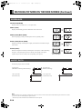
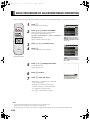
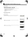
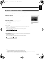
2004年11月16日 火曜日 午後2時21分
USER'S MANUAL
(Specification and Part Names)
Italiano
Français
Español
WIDE PLASMA DISPLAY
P42VHA40W/P42HHA40W/P50XHA40W/P55XHA40W
P42VHA40U/P42HHA40U/P50XHA40U/P55XHA40U
P42VHA40R
English
1 ページ
Deutsch
MHD01660-01_E.book
Page
Before Use
• CHECKING ACCESSORIES.................................................................................... E-2
• INSTALLATION ........................................................................................................ E-3
Usage
Português
Contents
• MAIN SUPPORTED SIGNALS............................................................................... E-10
• SPECIFICATION .................................................................................................... E-12
Before using the display, read the User’s manual (1/2) and the User’s manual (2/2) carefully so that you know how to use the
display correctly.
Refer to this manual whenever questions or problems about operation arise. Be sure to read and observe the safety
precautions (see the separate "Safety Precautions" manual).
Keep this manual where the user can see it easily.
* Installation and removal require special expertise. Consult your product dealer for details.
* When "English" is selected at "Language" of the on-screen display, "colour" will be displayed in the case of the R model and
"color" will be displayed for all other models.
The notation used in this users' manual is "color".
÷–Œƒ
• OPTIONS.................................................................................................................. E-9
日 本 語
Others
Póññêèé
• PART NAMES AND FUNCTIONS............................................................................ E-4
MHD01660-01_E.book
2 ページ
2004年11月16日 火曜日 午後2時21分
CHECKING ACCESSORIES
Display Section
One power cable
Two small
ferrite cores
Two big
ferrite cores
Three user's manuals
Manual
(for the W/R models)
One remote control
(for the W/R models)
One remote control
(for the U model)
Manual
Manual
(for the U model)
Two AA batteries
CONNECTING THE DISPLAY TO EXTERNAL EQUIPMENT
Carefully check the terminals for position and type before making any connections.
Loose connectors can result in picture or color problems. Make sure that all connectors are securely inserted into their terminals.
Ferrite cores
These ferrite cores are used to attenuate undesired signals.
Two big ferrite cores
When connecting a cable to the power input terminal, video input terminal (VIDEO1 INPUT), attach one of these ferrite cores to the cable
near the terminal.
Power Cable
RCA Video Cable
Ferrite Core
Ferrite Core
Two small ferrite cores
When connecting a cable to the external speaker output terminal attach one of these ferrite cores to the cable near the terminal.
Ferrite Core
E-2
Ferrite Core
MHD01660-01_E.book
3 ページ
2004年11月16日 火曜日 午後2時21分
English
INSTALLATION
Be sure to use the optional stand, wall-mounting unit or the other unit when installing the display. Also, be also sure that your dealer
performs the installation.
See the appropriate instruction manual for more information on the installation hardware you select.
To prevent an accident and ensure safety in the event of an earthquake, fix the display securely into position as described below.
To ensure proper heat radiation, provide at least as much space around the display as shown below.
Español
* Make sure that the display is installed in a location where the temperature can be maintained between 0°C and 40°C.
Deutsch
To prevent the display's internal components from overheating, make sure that the display is installed in a well-ventilated location.
* Never attempt to tilt the display sideways or backward.
* To prevent the power and other cables from being accidentally pulled, make sure that they run along the wall or through corners.
* To prevent accidents and ensure safety in the event of an earthquake, secure the display to prevent it from tipping over.
Front
Français
Display Section
Side
(cm)
(cm)
Upper
10
10
10
Wall
3.5 (for 42”/50”)
5 (for 55”)
÷–Œƒ
Póññêèé
Português
5
Lower
Right
Italiano
Left
日 本 語
Note
The display is a highly precise piece of equipment and therefore must be packed properly before transportation. Be sure to use only those packing
materials originally supplied with the display when repacking it.
Reference
See P. E-9 for more information on options.
E-3
MHD01660-01_E.book
4 ページ
2004年11月16日 火曜日 午後2時21分
PART NAMES AND FUNCTIONS
DISPLAY SECTION – FRONT
(Right section)
Power indicator lamp
This lamp shows the state of the power supply.
Lit (red):
Stand-by state
Lit (green):
Power ON state
Flashing (red or green):
Malfunction (Flashes differently
depending on the type of
malfunction.)
Remote control signal receiver
Receives signals from the remote control.
Input mode selector button
[MODE]
Input mode selector button
[MODE]
Switches between picture input modes.
VOL + button
VOL - button
Adjusts the audio volume.
Wide screen selector button [WIDE]
Switches the screen over to a desired wide screen.
ON/OFF button
Turns the power "ON" and "OFF (standby state)".
Ambient Sensor
Detects the brightness of external light.
Do not obstruct it.
Warning
If the power indicator lamp flashes red or green, this signifies that the display has developed a problem. When this happens, be sure to remove the
power plug from the receptacle and contact your dealer. Leaving the display power ON can result in fire or electric shock.
E-4
5 ページ
2004年11月16日 火曜日 午後2時21分
English
MHD01660-01_E.book
Póññêèé
Português
Italiano
Français
Español
Deutsch
DISPLAY SECTION – BACK AND BOTTOM PART
/ I power switch
If this button is pressed when the power indicator lamp is off, the indicator lamp will light.
The power can be turned on and the standby mode selected by using the remote control or the control panel of the display.
If this button is pressed when the power indicator lamp is lit, the indicator lamp will go out.
*Power is still supplied to parts of the display even if the indicator lamp is off.
÷–Œƒ
HDMI input terminal (VIDEO5 INPUT/HDMI) for the U model
Connect this terminal to the HDMI output terminal for DVD, etc.
RS-232C terminal (RS-232C)
This terminal is provided for you to control the display from the PC. Connect it to the RS-232C terminal on the PC.
日 本 語
RGB1 input terminal (RGB1 INPUT/DVI-D) for the W/U models
Connect this terminal to the PC’s display (digital RGB) output terminal.
*The connection cable No.88741-8000 made by molex Inc. is recommanded.
E-5
MHD01660-01_E.book
6 ページ
2004年11月16日 火曜日 午後2時21分
PART NAMES AND FUNCTIONS (Continued)
RGB2 input terminal (RGB2 INPUT/mD-sub) for the W/U models /
RGB1 input terminal (RGB1 INPUT/mD-sub) for the R model
Connect this terminal to the PC’s display (analog RGB) output terminal or decoder (digital broadcast tuner, etc.) output terminal.
Component video input terminal (VIDEO3 INPUT)
Component video input terminal (VIDEO4 INPUT)
Connect this terminal to the component video output (color difference output) terminal of your HDTV unit or DVD player.
Video input terminal (VIDEO1 INPUT)
Connect this terminal to the video output terminal of your VCR.
When connecting a cable, attach a ferrite core to the cable. (See P. E-2.)
S-Video input terminal (VIDEO2 INPUT)
Connect this terminal to the S-video output terminal of your VCR.
Audio3 input terminal (AUDIO3 INPUT)
Audio2 input terminal (AUDIO2 INPUT)
Audio1 input terminal (AUDIO1 INPUT)
Connect this terminal to the audio output terminal of your VCR, etc. (See the User’s manual (2/2) for the selection of audio input for video
input.)
" External speaker output terminal (EXT SP)
Connect this terminal to the optionally available speaker.
When connecting a cable, attach a ferrite core to the cable. (See P. E-2.)
* See the speaker instruction manual for more information.
# Power input terminal
Connect this terminal to the power cable supplied with the display.
When connecting a cable, attach a ferrite core to the cable. (See P. E-2.)
E-6
7 ページ
2004年11月16日 火曜日 午後2時21分
English
MHD01660-01_E.book
Signal
Pin No.
Signal
1
T.M.D.S. Data2– 9
T.M.D.S. Data1– 17
T.M.D.S. Data0–
2
T.M.D.S. Data2+ 10
T.M.D.S. Data1+ 18
T.M.D.S. Data0+
3
T.M.D.S. Data2 Shield 11
T.M.D.S. Data1 Shield 19
T.M.D.S. Data0 Shield
4
—
—
20
—
12
5
—
13
—
21
—
6
DDC Clock
14
+5V Power
22
T.M.D.S. Clock Shield
7
DDC Data
15
Ground (for +5V) 23
T.M.D.S. Clock+
8
—
16
Hot Ploug Detect 24
T.M.D.S. Clock–
Input signal
1
Red
9
—
2
Green
10
Ground
3
Blue
11
—
4
—
12
—
5
Ground
13
Horizontal synchronization
6
Ground
14
Vertical synchronization
7
Ground
15
—
8
Ground
Frame
Ground
RS-232C terminal (RS-232C)
Pin No.
Italiano
Pin No.
Português
Input signal
Póññêèé
Pin No.
Signal
1
DCD (Data Carrier Detect)
2
RD (Received Data)
3
TD (Transmit Data)
4
DTR (Data Terminal ready)
5
GND (Ground)
6
DSR (Data Set Ready)
7
RTS (Request To send)
8
CTS (Clear To Send)
9
RI (Ring Indication)
Español
Pin No.
Français
Signal
÷–Œƒ
mD-sub input terminal
(RGB2 INPUT/mD-sub) for the W/U models
(RGB1 INPUT/mD-sub) for the R model
Pin No.
日 本 語
DVI-D terminal (RGB1 INPUT/DVI-D)
for the W/U models
Deutsch
DESCRIPTION OF INPUT TERMINALS
E-7
MHD01660-01_E.book
8 ページ
2004年11月16日 火曜日 午後2時21分
PART NAMES AND FUNCTIONS (Continued)
HDMI input terminal (VIDEO5 INPUT/HDMI)
for the U model
Pin No.
Input signal
Pin No.
Input signal
1
T.M.D.S. Data2+
11
T.M.D.S. Clock Shield
2
T.M.D.S. Data2 Shield
12
T.M.D.S. Clock–
3
T.M.D.S. Data2–
13
CEC
4
T.M.D.S. Data1+
14
Reserve
5
T.M.D.S. Data1 Shield
15
DDC Clock
6
T.M.D.S. Data1–
16
DDC Data
7
T.M.D.S. Data0+
17
Ground (for +5V)
8
T.M.D.S. Data0 Shield
18
+5V Power
9
T.M.D.S. Data0–
19
Hot Plug Detect
10
T.M.D.S. Clock+
Frame
FG
HDMI (High-Definition Multimedia Interface)
HDMI is a standard for home digital interfaces, which can transmit images as well as multichannel
audio signals and control signals through one cable.
E-8
MHD01660-01_E.book
9 ページ
2004年11月16日 火曜日 午後2時21分
0° to 15° mounting angle
P-WB4201 (for 42” model/50” model)
Deutsch
Wall-mounting Bracket
English
OPTIONS
Ceiling unit
0° to 15° mounting angle
Español
P-WB6300 (for 55” model)
P-CT4200 (for 42” model/50” model)
P-TT4202 (for 42” model/50” model/55”
model)
Speaker
(1 set of 2 speakers)
P-SP1000 (for attaching to the display) for
42” model/50” model
Português
Italiano
Desktop Stand unit
Français
P-CT6300 (for 55” model)
P-SP5010 (for attaching to the display) for
55” model
P-SP4200 (for mounting on the speaker
stands) for 42” model
Póññêèé
Desktop Speaker Stand
(1 set of 2 speaker stands)
P-SP5010 (for mounting on the speaker
stands) for 50” model/55” model
P-ST4200 (for P-SP4200)
P-ST5000 (for P-SP5010)
* When installing an option, make sure that all installation requirements for that option (as given in the relevant instruction manual) are met.
* The colors of options do not match the display colors perfectly.
÷–Œƒ
* To improve the function and performance of optional accessories, specifications and part names may change. Consult your local dealer
before purchasing.
Warning
日 本 語
To prevent injury, fire, and electric shock, arrange for options to be initially installed (or installed at a different location) by your dealer.
CAUTION
This display (P42VHA40/P42HHA40/P50XHA40) is for use only with Fujitsu General Limited's option (P-WB4201, P-CT4200, P-TT4202).
This display (P55XHA40) is for use only with Fujitsu General Limited's option (P-WB6300, P-CT6300, P-TT4202).
Using this display with other option can cause instability resulting in possible injury.
E-9
MHD01660-01_E.book
10 ページ
2004年11月16日 火曜日 午後2時21分
MAIN SUPPORTED SIGNALS
This display can store the latest four types of signals for RGB adjustment value. The fifth input signal will replace the adjustment value of
the first input signal.
To do this, select a desired signal and follow the instructions in “Adjusting Screen Position and Size” on the User’s manual (2/2) to adjust
the parameters.
When you finish, the settings will be automatically stored. Thus, when the display receives that signal, pictures will be displayed in
accordance with the settings you most recently selected.
Main corresponding signals (RGB mode)
Display (dots x lines)
Horizontal frequency (kHz) Vertical frequency (Hz)
Signal
640 x 480
31.47
59.94
VGA
640 x 480
37.50
75.00
VGA 75 Hz
640 x 480
43.27
85.01
VGA 85 Hz
720 x 400
31.47
70.09
400 lines
800 x 600
37.88
60.32
SVGA 60 Hz
800 x 600
46.88
75.00
SVGA 75 Hz
800 x 600
53.67
85.06
SVGA 85 Hz
1024 x 768
48.36
60.00
XGA 60 Hz
1024 x 768
60.02
75.03
XGA 75 Hz
1024 x 768
68.68
84.99
XGA 85 Hz
1280 x 1024
63.98
60.02
SXGA 60 Hz
1280 x 1024
79.98
75.03
SXGA 75 Hz
848 x 480
31.02
60.00
852 x 480
31.72
59.97
1360 x 768
47.71
60.01
720 x 485
15.73
59.94
60 fields
720 x 575
15.63
50.00
50 fields
DVI-D
※
* With some input signals, "Out of range" may appear even when the horizontal and vertical frequencies are within their permissible
ranges. In this event, match the input signals to another frequency rather than those listed above.
※It doesn’t support the model with 42” display (displayed pixels 852 x 480 dots x lines).
* In the DVI-D mode, the input signal can be restricted partly.
E-10
11 ページ
2004年11月16日 火曜日 午後2時21分
English
MHD01660-01_E.book
Horizontal
frequency (kHz)
Vertical
frequency (Hz)
Signal
Main corresponding signals (Video, S-video mode)
HDMI
Horizontal
frequency (kHz)
15.73
Vertical
frequency (Hz)
59.94
Signal
15.73
59.94
SDTV 480i
NTSC
15.63
50.00
SDTV 576i
15.63
50.00
PAL
31.47
59.94
SDTV 480p
15.63
50.00
SECAM
31.25
50.00
SDTV 576p
15.63
59.52
PAL60
45.00
60.00
HDTV 720p
15.63
50.00
N-PAL
50.00
HDTV 720p
15.73
59.95
M-PAL
33.75
60.00
HDTV 1080i
15.73
59.94
4.43NTSC
28.13
50.00
HDTV 1080i
÷–Œƒ
Póññêèé
Português
Italiano
Français
37.50
Español
Main corresponding signals (Comp.video mode)
Deutsch
In the Comp.video and Video/S-video, the display has been factory-set as follows for different input signals:
•
•
•
•
•
日 本 語
Note
Depending on the input signal, the display may show pictures of reduced size due to size reduction and interpolation.
"Out of range" appears if the display receives a signal whose characteristic does not fall within the display's permissible range.
You can check input signals through "Information" on the FEATURES Menu screen. (See User's Manual (2/2))
In order to facilitate the explanations, pictures and diagrams in this manual may differ slightly from the actual items.
All terms (i.e., company and product names) used in this document are trademarks or registered trademarks.
E-11
MHD01660-01_E.book
12 ページ
2004年11月16日 火曜日 午後2時21分
SPECIFICATION
WIDE PLASMA DISPLAY
Model
Screen size
Aspect ratio
Number of pixels
Weight
Outer dimensions
Power supply
Current rating
External equipment terminals
Video input terminals
PC input terminal
Audio terminals
Control terminal
External speaker output terminal
Operating conditions
Accessories
P42VHA40W
P42HHA40W
42" wide screen:
42" wide screen:
92.1 cm (W) x 51.8
92.2 cm (W) x 52.2
cm (H)
cm (H)
(105.7 cm diagonal)
(106.0 cm diagonal)
36.3 inch (W) x 20.4
36.3 inch (W) x 20.6
inch (H)
inch (H)
(41.6 inch diagonal)
(41.7 inch diagonal)
16:9 (wide)
852 (H) x 480 (V)
1024 (H) x 1024 (V)
31.5 kg / 69 lbs
103.9 (W) x 64.0 (H) x 8.7 (D) cm
40.9 (W) x 25.2 (H) x 3.4 (D) inch
(does not include outer projections)
110-240 VAC 50/60 Hz
3.2-1.35 A
4.2-1.8 A
P55XHA40W
55" wide screen:
122.9 cm (W) x 69.1
cm (H)
(140.0 cm diagonal)
48.4 inch (W) x 27.2
inch (H)
(55.1 inch diagonal)
1366 (H) x 768 (V)
45 kg / 99 lbs
121.6 (W) x 72.6 (H) x
10.0 (D) cm
47.9 (W) x 28.6 (H) x
3.9 (D) inch
(does not include outer
projections)
55 kg / 121 lbs
138.0 (W) x 80.8 (H) x
12.5 (D) cm
54.3 (W) x 31.8 (H) x
4.9 (D) inch
(does not include outer
projections)
4.4-1.9 A
5.8-2.3 A
1 Vp-p/75 Ω
Y:
1 Vp-p/75 Ω
C:
0.286 Vp-p/75 Ω
VIDEO3/VIDEO4 INPUT
3 RCA terminals Y:
1 Vp-p/75 Ω
(Component video input)
PB/CB: 0.7 Vp-p/75 Ω
PR/CR: 0.7 Vp-p/75 Ω
RGB1 input
DVI-D terminal (EIA/CEA-861B Compliant)
RGB2 input
mD-sub, 3 rows, 15-pin
Picture signal: 0.7 Vp-p/75 Ω
Synchronization signal:TTL level
2 audio input pin jacks (L/R) (3 lines)
500 mVrms/at least 22 kΩ
RS-232C connector (D-sub 9-pin)
Max. output: 10 W + 10 W, 6 Ω
Temperature: 0 to 40 °C / 32 to 104 °F
Humidity:
20 to 80 %
3 user's manuals, 1 power cable, 2 small ferrite cores, 2 big ferrite cores, 1 remote control, 2 AA batteries
VIDEO1 INPUT (Video input)
VIDEO2 INPUT (S-video input)
Regulation
• UL, CSA Safety: UL6500, C-UL
EMC: FCC Part 15 Class B, ICES-003 Class B
• CE Safety: EN60065
EMC: EN55022
1998, Class B
EN61000-3-2
1995
EN61000-3-3
1995
EN55024
1998
EN61000-4-2
1995
EN61000-4-3
1996
EN61000-4-4
1995
EN61000-4-5
1995
EN61000-4-6
1996
EN61000-4-8
1993
EN61000-4-11 1994
• AS Safety: IEC60065
EMC: AS/NZS 3548
E-12
P50XHA40W
50" wide screen:
110.6 cm (W) x 62.2
cm (H)
(126.9 cm diagonal)
43.5 inch (W) x 24.5
inch (H)
(50 inch diagonal)
RCA terminal
S terminal
13 ページ
2004年11月16日 火曜日 午後2時21分
English
MHD01660-01_E.book
PC input terminal
Audio terminals
Control terminal
External speaker output terminal
Operating conditions
Accessories
4.4-1.9 A
5.8-2.3 A
1 Vp-p/75 Ω
Y:
1 Vp-p/75 Ω
C:
0.286 Vp-p/75 Ω
VIDEO3/VIDEO4 INPUT
3 RCA terminals Y:
1 Vp-p/75 Ω
(Component video input)
PB/CB: 0.7 Vp-p/75 Ω
PR/CR: 0.7 Vp-p/75 Ω
VIDEO5 INPUT
HDMI terminal (HDMI type A connector)
RGB1 input
DVI-D terminal (EIA/CEA-861B Compliant)
RGB2 input
mD-sub, 3 rows, 15-pin
Picture signal: 0.7 Vp-p/75 Ω
Synchronization signal:TTL level
2 audio input pin jacks (L/R) (3 lines)
500 mVrms/at least 22 kΩ
RS-232C connector (D-sub 9-pin)
Max. output: 10 W + 10 W, 6 Ω
Temperature: 0 to 40 °C / 32 to 104 °F
Humidity:
20 to 80 %
3 user's manuals, 1 power cable, 2 small ferrite cores, 2 big ferrite cores, 1 remote control, 2 AA batteries
VIDEO1 INPUT (Video input)
VIDEO2 INPUT (S-video input)
RCA terminal
S terminal
Regulation
÷–Œƒ
• UL, CSA Safety: UL6500, C-UL
EMC: FCC Part 15 Class B, ICES-003 Class B
• CE Safety: EN60065
EMC: EN55022
1998, Class B
EN61000-3-2
1995
EN61000-3-3
1995
EN55024
1998
EN61000-4-2
1995
EN61000-4-3
1996
EN61000-4-4
1995
EN61000-4-5
1995
EN61000-4-6
1996
EN61000-4-8
1993
EN61000-4-11 1994
• AS Safety: IEC60065
EMC: AS/NZS 3548
Español
55 kg / 121 lbs
138.0 (W) x 80.8 (H) x
12.5 (D) cm
54.3 (W) x 31.8 (H) x
4.9 (D) inch
(does not include outer
projections)
Français
1366 (H) x 768 (V)
45 kg / 99 lbs
121.6 (W) x 72.6 (H) x
10.0 (D) cm
47.9 (W) x 28.6 (H) x
3.9 (D) inch
(does not include outer
projections)
Italiano
110-240 VAC 50/60 Hz
3.2-1.35 A
4.2-1.8 A
P55XHA40U
55" wide screen:
122.9 cm (W) x 69.1
cm (H)
(140.0 cm diagonal)
48.4 inch (W) x 27.2
inch (H)
(55.1 inch diagonal)
Português
Power supply
Current rating
External equipment terminals
Video input terminals
P50XHA40U
50" wide screen:
110.6 cm (W) x 62.2
cm (H)
(126.9 cm diagonal)
43.5 inch (W) x 24.5
inch (H)
(50 inch diagonal)
Póññêèé
Aspect ratio
Number of pixels
Weight
Outer dimensions
P42VHA40U
P42HHA40U
42" wide screen:
42" wide screen:
92.1 cm (W) x 51.8
92.2 cm (W) x 52.2
cm (H)
cm (H)
(105.7 cm diagonal)
(106.0 cm diagonal)
36.3 inch (W) x 20.4
36.3 inch (W) x 20.6
inch (H)
inch (H)
(41.6 inch diagonal)
(41.7 inch diagonal)
16:9 (wide)
852 (H) x 480 (V)
1024 (H) x 1024 (V)
31.5 kg / 69 lbs
103.9 (W) x 64.0 (H) x 8.7 (D) cm
40.9 (W) x 25.2 (H) x 3.4 (D) inch
(does not include outer projections)
Note
• Specifications and external appearance may be change for the sake of improvement.
• Viewing the screen constantly for extended periods can strain your eyes. Be sure to stay at a proper distance (at least 1.5 m or 5 feet for 42" / at least
1.9 m or 6.2 feet for 50" / at least 2.1 m or 6.9 feet for 55") from the screen and to look occasionally away while working.
•
is a worldwide trademark of Fujitsu General Limited and is a registered trademark in Japan, the U.S.A. and other countries or
areas.
E-13
日 本 語
Model
Screen size
Deutsch
WIDE PLASMA DISPLAY
MHD01660-01_E.book
14 ページ
2004年11月16日 火曜日 午後2時21分
SPECIFICATION (Continued)
WIDE PLASMA DISPLAY
Model
Screen size
Aspect ratio
Number of pixels
Weight
Outer dimensions
Power supply
Current rating
External equipment terminals
Video input terminals
P42VHA40R
42" wide screen:
92.1 cm (W) x 51.8 cm (H) (105.7 cm diagonal)
36.3 inch (W) x 20.4 inch (H) (41.6 inch diagonal)
16:9 (wide)
852 (H) x 480 (V)
31.5 kg / 69 lbs
103.9 (W) x 64.0 (H) x 8.7 (D) cm
40.9 (W) x 25.2 (H) x 3.4 (D) inch
(does not include outer projections)
110-240 VAC 50/60 Hz
3.2-1.35 A
VIDEO1 INPUT (Video input)
VIDEO2 INPUT (S-video input)
VIDEO3/VIDEO4 INPUT
(Component video input)
PC input terminal
Audio terminals
Control terminal
External speaker output terminal
Operating conditions
Accessories
1 Vp-p/75 Ω
Y:
1 Vp-p/75 Ω
C:
0.286 Vp-p/75 Ω
3 RCA terminals Y:
1 Vp-p/75 Ω
PB/CB: 0.7 Vp-p/75 Ω
PR/CR: 0.7 Vp-p/75 Ω
RCA terminal
S terminal
RGB1 input
mD-sub, 3 rows, 15-pin
Picture signal: 0.7 Vp-p/75 Ω
Synchronization signal:TTL level
2 audio input pin jacks (L/R) (3 lines)
500 mVrms/at least 22 kΩ
RS-232C connector (D-sub 9-pin)
Max. output: 10 W + 10 W, 6 Ω
Temperature: 0 to 40 °C / 32 to 104 °F
Humidity:
20 to 80 %
3 user's manuals, 1 power cable, 2 small ferrite cores, 2 big ferrite cores, 1 remote control, 2 AA batteries
Regulation
• UL, CSA Safety: UL6500, C-UL
EMC: FCC Part 15 Class B, ICES-003 Class B
• CE Safety: EN60065
EMC: EN55022
1998, Class B
EN61000-3-2
1995
EN61000-3-3
1995
EN55024
1998
EN61000-4-2
1995
EN61000-4-3
1996
EN61000-4-4
1995
EN61000-4-5
1995
EN61000-4-6
1996
EN61000-4-8
1993
EN61000-4-11 1994
• AS Safety: IEC60065
EMC: AS/NZS 3548
Note
• Specifications and external appearance may be change for the sake of improvement.
• Viewing the screen constantly for extended periods can strain your eyes. Be sure to stay at a proper distance (at least 1.5 m or 5 feet for 42" / at least
1.9 m or 6.2 feet for 50" / at least 2.1 m or 6.9 feet for 55") from the screen and to look occasionally away while working.
•
is a worldwide trademark of Fujitsu General Limited and is a registered trademark in Japan, the U.S.A. and other countries or
areas.
E-14
1 ページ
2004年11月16日 火曜日 午後4時33分
USER'S MANUAL
(Precautions and Adjustment Methods)
Italiano
Français
Español
Deutsch
WIDE PLASMA DISPLAY
English
MHD01661-01_E.book
Before Use
• INFORMATION ............................................................E-2
Usage
• USING THE REMOTE CONTROL...............................E-3
Page
• OTHER ADJUSTMENTS ...........................................E-29
• INITIALIZATION OF USER ADJUSTMENT VALUE ..E-35
Others
• CLEANING AND MAINTENANCE .............................E-36
Português
Contents
Page
EQUIPMENT ................................................................E-7
• BASIC OPERATIONS ................................................E-12
• SELECTING INPUT MODE .......................................E-14
• OTHER BASIC OPERATIONS ..................................E-16
• WATCHING PICTURES ON THE WIDE SCREEN....E-17
Póññêèé
• CONNECTING THE DISPLAY TO EXTERNAL
Adjustments
• ADJUSTMENT MENU................................................E-19
• BASIC PROCEDURE OF ADJUSTMENT MENU
OPERATIONS............................................................E-20
• ADJUSTING THE PICTURE ......................................E-21
• ADJUSTING SCREEN POSITION AND SIZE ...........E-27
日本語
Before using the display, read the User’s manual (1/2) and the User’s manual (2/2) carefully so that you know how to use the
display correctly.
Refer to this manual whenever questions or problems about operation arise. Be sure to read and observe the safety
precautions (see the separate "Safety Precautions" manual).
Keep this manual where the user can see it easily.
* Installation and removal require special expertise. Consult your product dealer for details.
* When "English" is selected at "Language" of the on-screen display, "colour" will be displayed in the case of the R model and
"color" will be displayed for all other models.
The notation used in this users' manual is "color".
中文
• ADJUSTING AUDIO...................................................E-28
MHD01661-01_E.book
2 ページ
2004年11月16日 火曜日 午後4時33分
INFORMATION
• Receptacle
Make sure that the power cable’s grounding wire is grounded.
The display comes with a 3-prong power plug; one prong is connected to the grounding wire. If you have only a 2-hole receptacle, you
will need to have it replaced. Contact your dealer for more information.
• Have the display inspected and cleaned by your dealer at regular intervals.
• Pictures may become “burnt” into the screen phosphors if the screen is left on for extended periods. To ensure that the display has a
prolonged service life, be sure to use a screen orbiter, white screen. This will ensure the same picture or pattern is not constantly
displayed for long periods. (See P. E-33.)
• Extremely high-precision technology has been used in the manufacture of the plasma display panel, with the effective pixel elements
exceeding 99.99%. Please be aware, however, that fewer than 0.01% of the pixels may be missing or remain constantly lit.
• Some models are fitted with a radiator fan to prevent the display’s internal temperature from rising during operation. Be careful of the air
emitted by the radiator fan, as it may be hot.
• Contact your dealer if you find that the display does not seem to function properly when used with other audio-visual equipment.
You may need to move your display if it produces degraded pictures or noise due to electromagnetic radiation, or if the infrared remote
control does not function properly.
• Pictures may not be displayed properly if you connect a non-standard PC to the RGB input terminal. In this case, contact your dealer for
more information.
• The protective circuit, built into the display, automatically turns off the power if the display has a problem. In this case, you will see that
the power indicator lamp flashes red or green.
Warning
If the power indicator lamp flashes red or green, this signifies that the display has developed a problem. When this happens, be sure to remove the
power plug from the receptacle to prevent fire or electric shock. Then contact your dealer.
• Install the display in a location close to a main power supply outlet, and where the emergency stop button can be easily reached.
Note
• Cables for connecting the display to external equipment are not supplied. Contact your dealer for more information on these products.
• In order to facilitate the explanations, pictures and diagrams in this manual may differ slightly from the actual items.
E-2
MHD01661-01_E.book
3 ページ
2004年11月16日 火曜日 午後4時33分
English
USING THE REMOTE CONTROL
For details, see page Î.
Deutsch
REMOTE CONTROL (for the W/R models)
button Î E-12
- (MUTE button) Î E-13
Temporarily mutes the audio.
To return the audio to normal, press this button once again, or press the
work also.
2
3 (DISPLAY button) Î E-16
1 does the
Français
Press this button to display the input mode, and screen size status.
The status is displayed for about five seconds.
4 (PICTURE MODE button) Î E-16
Use this button to switch the Picture Mode.
Español
Switches between Power On and Standby.
5 (PICTURE MEMORY button) Î E-16
Press this button to recall a Picture Memory.
(WIDE button) Î E-17
Italiano
Switches the screen size.
) – * (RGB input mode selector button) Î E-15
Selects RGB1 - 2.
Português
= (RGB3/VIDEO4 imput mode selector button) Î E-14
Selects VIDEO4.
" – $ (Video input mode selector button) Î E-14
Selects VIDEO1 - 3.
12 (Volume adjustment buttons) Î E-13
Press these buttons to adjust the volume.
; (MENU button) Î E-19–E-35
Press this button to display the menu screen for adjusting the picture and/or the audio.
< (ENTER button) Î E-19–E-35
Póññêèé
Press this button to fix the entry in the ADJUSTMENT MENU.
"
CDEF (Adjustment buttons) Î E-19–E-35
日本語
中文
Use these buttons to select the item or adjust the value in the menu screen.
Note
• Functions may not be available with some models and some device options.
E-3
MHD01661-01_E.book
4 ページ
2004年11月16日 火曜日 午後4時33分
USING THE REMOTE CONTROL (Continued)
REMOTE CONTROL (for the U model)
For details, see page Î.
button Î E-12
Switches between Power On and Standby.
- (MUTE button) Î E-13
Temporarily mutes the audio.
To return the audio to normal, press this button once again, or press the
work also.
2
3 (DISPLAY button) Î E-16
1 does the
Press this button to display the input mode, and screen size status.
The status is displayed for about five seconds.
4 (PICTURE MODE button) Î E-16
Use this button to switch the Picture Mode.
5 (PICTURE MEMORY button) Î E-16
Press this button to recall a Picture Memory.
(WIDE button) Î E-17
Switches the screen size.
" – & (Video input mode selector button) Î E-14
Selects VIDEO1 - 5.
) – * (RGB input mode selector button) Î E-15
Selects RGB1 - 2.
12 (Volume adjustment buttons) Î E-13
Press these buttons to adjust the volume.
; (MENU button) Î E-19–E-35
Press this button to display the menu screen for adjusting the picture and/or the audio.
< (ENTER button) Î E-19–E-35
Press this button to fix the entry in the ADJUSTMENT MENU.
CDEF (Adjustment buttons) Î E-19–E-35
Use these buttons to select the item or adjust the value in the menu screen.
Note
• Functions may not be available with some models and some device options.
E-4
5 ページ
2004年11月16日 火曜日 午後4時33分
English
MHD01661-01_E.book
Español
Deutsch
PUTTING BATTERIES IN THE REMOTE CONTROL
(2) Place two AA batteries in the remote
control. Make sure that the batteries are
properly oriented.
(3) Close the cover until it snaps into place.
Français
(1) To remove the cover, slide it outwards
while pressing it down.
PRECAUTIONS
To prevent malfunction or deformation, be sure not to allow the remote control to become wet; also, keep it away from hot locations or
heating equipment.
中文
Póññêèé
Português
Be sure not to clean the remote control using a cloth dampened in any volatile solvent, such as benzene or thinner.
Italiano
To prevent malfunction, be sure not to apply any form of severe shock to the remote control.
Be sure to use replacement batteries of the same type as the original ones.
When disposing of used batteries, please comply with governmental regulations or environmental public institution’s rules that apply in your country/
area.
Note
The remote control will not function properly if the batteries are dead. Be sure to replace them as needed.
Do not use rechargeable batteries (Ni-Cd, etc.).
E-5
日本語
CAUTION
MHD01661-01_E.book
6 ページ
2004年11月16日 火曜日 午後4時33分
USING THE REMOTE CONTROL (Continued)
EFFECTIVE RANGE FOR THE REMOTE CONTROL
Point the remote control at the display’s signal receiver when using it.
Make sure that there are no obstacles between the remote control and the display’s signal receiver.
Upper
20°
20°
Lower
Left
30°
30°
Right
5 m (Front)
Note
The remote control may not function properly if you use a high-frequency fluorescent lamp. If you experience problems, move the lamp or use the
remote control from a different position.
E-6
7 ページ
2004年11月16日 火曜日 午後4時33分
CONNECTING THE DISPLAY TO EXTERNAL EQUIPMENT
English
MHD01661-01_E.book
Speaker
Display
Deutsch
EXAMPLE OF CONNECTION TO EXTERNAL COMPONENTS
Speaker (optional)
Français
Español
Remote
control
Italiano
To AC outlet
Satellite tuner Î E-10
Póññêèé
VCR Î E-8
Português
VCR or other external components See P. Î
PC Î E-11
日本語
中文
DVD recorder/player Î E-9
E-7
MHD01661-01_E.book
8 ページ
2004年11月16日 火曜日 午後4時33分
CONNECTING THE DISPLAY TO EXTERNAL EQUIPMENT (Continued)
VCR
• Connect the video signal cable to either the S-video input terminal or the video input terminal.
• If the unit to be connected is equipped with S-video output terminal, it is recommended to connect to the S-video terminal.
To video output
To S-video output
To audio outputs
To S-video input
To audio inputs
To video input
Display bottom
E-8
9 ページ
2004年11月16日 火曜日 午後4時33分
English
MHD01661-01_E.book
Español
• Connect the video signal cable to the HDMI input terminal, component video input terminal, S-video input terminal, or the video input
terminal.
• If the component to be connected is equipped with HDMI output terminal, component video output terminal, it is recommended to connect
to the component video terminal.
Deutsch
DVD RECORDER/PLAYER
Français
To component video output
To video output
To audio outputs
To video input
To S-video input
To component video input
Português
To audio inputs
Italiano
To S-video output
Póññêèé
Display bottom
To HDMI output
中文
To HDMI input
•
•
•
•
日本語
Note
Unplug the power cord from the AC outlet before you connect external components.
Also refer to the instructions for the component to be connected.
When inputting audio, connect to the terminals corresponding to the used video input or RGB input.
Terminal layout may differ and functions may not be available with some models and some device options.
E-9
MHD01661-01_E.book
10 ページ
2004年11月16日 火曜日 午後4時33分
CONNECTING THE DISPLAY TO EXTERNAL EQUIPMENT (Continued)
SATELLITE TUNER
• Connect the video signal cable to the HDMI input terminal, component video input terminal, S-video input terminal, or the video input
terminal.
• If the component to be connected is equipped with HDMI output terminal, component video output terminal, it is recommended to connect to the
component video terminal.
Antenna (commercially available product)
To component video output
To video output
To S-video output
To audio outputs
To video input
To S-video input
To audio inputs
To component video input
Display bottom
To HDMI output
To HDMI input
E-10
11 ページ
2004年11月16日 火曜日 午後4時33分
English
MHD01661-01_E.book
Français
Español
• As the cable for connecting a PC differs with the PC model, please consult your dealer for information on the right cable to purchase.
Deutsch
PC
To RGB output (DVI-D)
Italiano
To DVI-D input
To RGB output (mD-sub)
To mD-sub input
To audio output
Póññêèé
Português
To audio inputs
中文
Display bottom
•
•
•
•
日本語
Note
Unplug the power cord from the AC outlet before you connect external components.
Also refer to the instructions for the component to be connected.
When inputting audio, connect to the terminals corresponding to the used video input or RGB input.
Terminal layout may differ and functions may not be available with some models and some device options.
E-11
MHD01661-01_E.book
12 ページ
2004年11月16日 火曜日 午後4時33分
BASIC OPERATIONS
TURNING THE POWER ON AND STAND-BY
* You can also use the buttons
on the display’s control
panel to perform these steps.
(for the W/R models)
* You can also use the buttons
on the display’s control
panel to perform these steps.
(for the U model)
E-12
1
Press/I to the left at the bottom of
the display to the ONstate.
2
Press
3
Press
4
Press
The power lamp lights up.
on the remote control.
The color of the power lamp changes from “Red” to
“Green”.
" – & or ) – *.
Select the video mode to input.
when the power is ON.
The color of the power lamp changes from “Green”
to “Red” and the the power turns “OFF (Stand-by
state)”.
13 ページ
2004年11月16日 火曜日 午後4時33分
English
MHD01661-01_E.book
Adjusting the volume
1 to increase the volume.
Press 2 to reduce the volume.
Press
* Note that the volume level remains stored even when you
turn OFF the power.
Muting the audio
-.
Français
Press
When the volume adjustment button is
pressed
Español
Deutsch
ADJUSTING THE VOLUME
The audio is removed.
Press again to restore the audio to the original level.
Italiano
The mute mode can also be released by pressing the volume
buttons.
Português
* You can also use the buttons
on the display’s control
panel to perform these steps.
日本語
中文
Póññêèé
(Ex. the W model)
Note
• Functions may not be available with some models and some device options.
E-13
MHD01661-01_E.book
14 ページ
2004年11月16日 火曜日 午後4時33分
SELECTING INPUT MODE
VIDEO INPUT MODE (for the W/R models)
1
Press
to select the input mode.
You can select from VIDEO1 mode to VIDEO4
mode.
The video modes corresponding to each input
terminal are as follows.
• VIDEO1: Video
• VIDEO2: S-video
• VIDEO3: Component video
Video1 mode
• VIDEO4: Component video
* For selection of the input terminal, see
“SETTING THE INPUT TERMINALS” on
P. E-31.
* You can also use the buttons
on the display’s control
panel to perform these steps.
VIDEO INPUT MODE (for the U model)
1
Press
to select the input mode.
You can select from VIDEO1 mode to VIDEO5
mode.
The video modes corresponding to each input
terminal are as follows.
• VIDEO1: Video
• VIDEO2: S-video
• VIDEO3: Component video
• VIDEO4: Component video
• VIDEO5: HDMI
* For selection of the input terminal, see
“SETTING THE INPUT TERMINALS” on
P. E-31.
* You can also use the buttons
on the display’s control
panel to perform these steps.
E-14
Video1 mode
15 ページ
2004年11月16日 火曜日 午後4時33分
English
MHD01661-01_E.book
1
Press
Deutsch
RGB INPUT MODE
to select the input mode.
You can select between the modes from RGB1 to
RGB2.
The input terminal of each RGB mode is as follows.
Español
[for the W/U models]
• RGB1: DVI-D
• RGB2: mD-sub
[for the R model]
RGB1 mode
Français
• RGB1: mD-sub
Italiano
* For selection of the input terminal, see
“SETTING THE INPUT TERMINALS” on
P. E-31.
日本語
中文
Póññêèé
Português
* You can also use the buttons
on the display’s control
panel to perform these steps.
(Ex. the U model)
E-15
MHD01661-01_E.book
16 ページ
2004年11月16日 火曜日 午後4時33分
OTHER BASIC OPERATIONS
CONVENIENT FUNCTIONS
On-screen information
Press
3.
The mode is indicated on the screen for 5 seconds.
Picture Mode
Press
4.
This button can be used to switch the picture mode.
In the picture mode, you can switch between the set status and the fine mode.
* For the picture mode settings, see “Setting Picture Mode (P. E-22)”.
Picture Memory
Press
5.
This button can be used to recall the settings of the picture memories 1 – 8. Each time this button is
pressed, the setting changes as follows.
* For the picture memory settings, see “Setting Picture Memory (P. E-22)”.
(Ex. the W/R models)
Note
• Functions may not be available with some models and some device options.
E-16
MHD01661-01_E.book
17 ページ
2004年11月16日 火曜日 午後4時33分
English
WATCHING PICTURES ON THE WIDE SCREEN
1
Press
2
Press
Size.
Deutsch
SWITCHING BETWEEN SCREEN SIZES
.
to select a desired Screen
Each time you press , a different Screen Size
appears. The sequences used are as follows:
Español
The currently selected mode will appear.
Normal mode
Français
When you are in a Video input mode
* Depending on the type of signal, some aspects
may not be selected.
Italiano
When you are in an RGB input mode
Wide1 mode
Português
* You can also use the buttons
on the display’s control
panel to perform these steps.
Note
• Displaying a picture in a Normal mode for extended periods of time may cause phosphor burn-in.
• A variety of Screen Sizes are available with this display. Remember that if you select a mode with an aspect ratio (ratio of frame width to frame
height) different from that of the TV program or video media, the pictures will appear differently than if you had selected a mode having the same
aspect ratio.
• Showing a movie or similar premium event at a different aspect ratio from its original one at any event site, restaurant, or bar for profit-making
purposes or for a public audience may constitute a copyright infringement.
For films, try to select a mode having the same aspect ratio as the original picture; this enables the director’s original intentions to be preserved.
• See P. E-27 for how to adjust the picture size and position.
E-17
日本語
中文
Póññêèé
(Ex. the W/R models)
MHD01661-01_E.book
18 ページ
2004年11月16日 火曜日 午後4時33分
WATCHING PICTURES ON THE WIDE SCREEN (Continued)
SCREEN SIZE
Normal (Video/RGB)
Displays pictures of normal size (i.e., a 4:3 aspect ratio).
Wide1 (Video)
Displays natural-looking pictures of standard size on the wide screen.
Picture of
standard size
Wide1
Vertically
extended picture
Wide2
Horizontally
extended picture
Zoom1
Horizontally extended
picture with caption
Zoom2
Wide2 (Video)/Wide (RGB)
Ideal for displaying vertically extended pictures such as squeezed pictures.
Zoom1 (Video)/Zoom (RGB)
Enlarges horizontally extended pictures equally in all directions to maintain the aspect
ratio constant.
Zoom2 (Video)
Reduces the height of horizontally extended pictures with captions, without eliminating
the caption. Only the height of pictures is reduced, not the height of the caption.
(Captions may not be easy to read, however, depending on the picture.)
ASPECT RATIO
The following aspect ratios are available.
4:3 aspect ratio
(VHF/UHF broadcasting, BS broadcasting)
4
16:9 aspect ratio
(HDTV broadcasting)
16
3
1.85:1 aspect ratio
(Vista Vision size)
9
1.85
1
2.35:1 aspect ratio
(Cinema Vision size)
2.35
1
Note
You may find dark areas on top and at the bottom of the screen if you select one of the Zoom modes for media while using the Vista Vision or Cinema
Vision size i.e., the sizes used frequently for picture software.
• Functions may not be available with some models and some device options.
E-18
MHD01661-01_E.book
19 ページ
2004年11月16日 火曜日 午後4時33分
English
ADJUSTMENT MENU
Signal Contrast
(E-21)
Drive Contrast
(E-21)
Black Level
(E-23)
AUDIO
(E-28)
Brightness
(E-21)
Detail Gradation
(E-23)
FEATURES
(E-29)
Color
(E-21)
3D NR
(E-23)
Tint
(E-21)
CODEC NR
(E-23)
Sharpness
(E-21)
Image Enhance
(E-24)
Chroma Transient (E-24)
Ambient Sensor
(E-21)
Color Temp.
(E-24)
Image identify
(E-24)
Picture Mode
(E-22)
User Color Temp. (E-24)
24 Frame Mode
(E-26)
30 Frame Mode
(E-26)
FACTORY DEFAULT(E-35)
PrecisionSetting (E-22)
Color Focus
Picture Memory
Progressive Scan (E-26)
(E-22)
(E-25)
Default
Position
(E-27)
Size
(E-27)
Jaggies Filter
(E-26)
Motion Setting
(E-26)
Default
(E-28)
Loudness
(E-28)
Adjustment
(E-29)
Dot Clock
(E-29)
On Screen Menu (E-30)
Clock Phase
(E-29)
Input Terminal
(E-31)
Clamp Position
(E-29)
Others
(E-32)
Auto Calibration
(E-29)
OSD
(E-30)
Language
(E-30)
Name Select
(E-30)
Video Input
(E-31)
S-video Input
(E-31)
D-SUB Input
(E-31)
Português
(E-28)
Balance
Italiano
(E-28)
Bass
Póññêèé
Treble
Español
MENU
(E-20)
POSITION/SIZE (E-27)
Français
PICTURE
Deutsch
The numbers in parentheses ( ) indicate the reference page numbers.
Auto Off-NO SIG. (E-32)
Audio Input
(E-32)
Screen Orbiter
(E-33)
Direct Setting
(E-33)
(E-33)
White Screen
(E-33)
Exhibition Mode
(E-34)
Information
(E-34)
日本語
中文
Code Setting
Note
• The shaded menu items are applied to the U model only.
• Some type of signal can not be selected.
E-19
MHD01661-01_E.book
20 ページ
2004年11月16日 火曜日 午後4時33分
BASIC PROCEDURE OF ADJUSTMENT MENU OPERATIONS
• Below is shown the basic procedure to make changes to the options in the ADJUSTMENT MENU. (Ex.: adjusting tint setting (Tint))
1
Press
2
Press
;.
The main menu screen will appear.
E or F to select “PICTURE”.
Each time you press E or F, one of the available
menus appears in the following sequence:
PICTURE < POSITION/SIZE < AUDIO < FEATURES <
FACTORY DEFAULT
The PICTURE Menu screen will appear.
3
4
Press
C or D to select “Tint”.
Press
<.
“PICTURE” selected in the main
menu screen
The “Tint” adjustment screen will appear.
(Ex. the W/R models)
“Tint” selected in the PICTURE
Menu screen
5
Press
6
7
Press
< to store.
Press
; when you finish.
E or F to change tint values.
F: More greenish colors
E: More purplish colors
“Tint” adjustment screen
* Repeat steps 3, 4, 5 and 6 when you wish to make
changes to other options.
* When < is pressed after you have selected
“Default”, the settings are returned to those that
were valid when you purchased the set.
* Press
; to halt the operation in progress.
Note
• On-screen information disappears if you do not take any action for about 60 seconds.
• Functions may not be available with some models and some device options.
• The adjustment range varies with the display signal. You can adjust the display quality to the value you want within the adjustable range.
E-20
MHD01661-01_E.book
21 ページ
2004年11月16日 火曜日 午後4時33分
English
ADJUSTING THE PICTURE
Deutsch
• Picture-related items can be set and adjusted in the Picture Adjustment Screen. See BASIC PROCEDURE OF ADJUSTMENT MENU
OPERATIONS on page E-20 for the basic operation procedures.
Adjusting the Signal Contrast
Press F to increase the input signal contrast.
Press E to reduce the input signal contrast.
Press < to store.
Español
Adjusting the Drive Contrast
Press F to raise the display’s luminance level, and increase the contrast.
Press E to lower the display’s luminance level, and reduce the contrast.
Press < to store.
Adjusting the Brightness
Français
Press F to increase the brightness.
Press E to reduce the brightness.
Press < to store.
Adjusting Color
Press F to darken the color.
Press E to lighten the color.
Italiano
Press < to store.
Adjusting the Tint
Press F to change the tint to a more greenish color.
Press E to change the tint to a more purplish color.
Português
Press < to store.
Adjusting the Sharpness
Press F to sharpen the Sharpness.
Press E to soften the Sharpness.
Press < to store.
Póññêèé
Adjusting the Ambient Sensor
Automatically adjusts the Sharpness to an optimized level that matches the brightness of the surrounding area.
Each time E or F is pressed, the setting is switched.
On < Off
中文
Press < to store.
•
•
•
•
日本語
Note
The screen display disappears if there is no operation within approximately 60 seconds.
Depending on the model or the optional devices, some of the functions may not be available.
The adjustment range varies according to the display signals. Make adjustments to your preferred Sharpness within the adjustment range.
Depending on the type of signal, it may not be possible to make some of the settings or adjustments.
E-21
MHD01661-01_E.book
22 ページ
2004年11月16日 火曜日 午後4時33分
ADJUSTING THE PICTURE (Continued)
Setting Picture Mode
Each time you press E or F , the available choices appear in the following sequence.
[Natural]: Enables you to watch pictures with natural color tones and high picture clarity. This
mode is suitable for watching a normal motion picture.
[Fine]: Suitable for watching a dark picture such as a movie.
[Effective]: Displays a screen with detailed contrast.
[Conventional]: Displays a screen approximating that of a conventional TV screen.
[Still]: Suitable for viewing a still picture.
Press < to store.
Precision Setting (for the U model)
Enables advanced Sharpness adjustments.
See page E-23 for details.
Setting Picture Memory
The adjustment status of eight groups of picture adjustment settings can be stored, enabling you to
quickly switch to your desired group of settings for the picture you are planning to watch.
Picture Memory Selection Screen
[Save]: Use C or D to select Memory 1 - 8. If < is pressed, the current picture adjustment
values are stored to the selected Memory.
[Load]: Use C or D to select Memory 1 - 8. When < is pressed, the values becomes the picture
adjustment values stored in the selected Memory.
“Save” Selection Screen
“Load” Selection Screen
E-22
23 ページ
2004年11月16日 火曜日 午後4時33分
English
MHD01661-01_E.book
Deutsch
PRECISION SETTING (for the U model)
• See BASIC PROCEDURE OF ADJUSTMENT MENU OPERATIONS on page E-20.
Even more advanced Sharpness adjustments can be made as required.
Adjusting the Black Level
Press E to weaken the reproduction of black.
Press < to store.
Setting Detail Gradation
Corrects the gradation of the light and dark areas of the picture.
Each time E or F is pressed, the setting is switched.
Press < to store.
Precision Setting Selection
Screen
Italiano
On < Off
Français
Español
Press F to strengthen the reproduction of black. (Provides a picture quality with deep blacks.)
Setting 3D NR
This enables noise reduction processing with respect to the input signal noise level (reduces screen
flicker for more comfortable viewing).
Português
Each time you press E or F, the available choices appear in the following sequence.
Press < to store.
Setting CODEC NR
Póññêèé
This enables noise reduction processing of mosquito noise or block noise generated when digital picture
signals are recorded or replayed.
Each time you press E or F, the available choices appear in the following sequence.
中文
Press < to store.
•
•
•
•
日本語
Note
The screen display disappears if there is no operation within approximately 60 seconds.
Depending on the model or the optional devices, some of the functions may not be available.
The adjustment range varies according to the display signals. Make adjustments to your preferred Sharpness within the adjustment range.
Depending on the type of signal, it may not be possible to make some of the settings or adjustments.
E-23
MHD01661-01_E.book
24 ページ
2004年11月16日 火曜日 午後4時33分
ADJUSTING THE PICTURE (Continued)
Setting Image Enhance
This performs detailed image quality settings.
• Chroma Transient
This function corrects the color contours.
Each time E or F is pressed, the setting is switched.
On < Off
Press < to store.
• Image Identify
This function discerns between the natural image display section and the text display section, and performs correction to enable an
optimized display for each.
Each time E or F is pressed, the setting is switched.
On < Off
Press < to store.
Adjusting the Color Temp.
Use E or F to specify a desired color temperature. Each time you press E or F, one of the available choices appears in the following
sequence:
[–3500]: More reddish colors
[+3500]: More bluish colors
[User]: User Color Temp. setup
Press < to store.
Setting User Color Temp.
Use C or D to select Red, Green, or Blue, and adjust the color temp. for each.
Press F: to strengthen the selected color.
Press E: to weaken the selected color.
Press < to store.
E-24
25 ページ
2004年11月16日 火曜日 午後4時33分
English
MHD01661-01_E.book
Setting the Color Focus
Deutsch
This enables correction with respect to specific color hues within the image.
Independent correction of the hue of skin colors, blue skies, and so on, enables a more brilliant display.
• [Reddish color]
Color Focus (Reddish color)
Settings Screen
Adjustments can be made in the same way for:
• [Greenish color]: (With green at the center, performs corrections with respect to the range from yellow to cyan.)
• [Bluish color]: (With blue at the center, performs corrections with respect to the range from cyan to magenta.)
Français
[Tint]: Use E and F to adjust the hue.
[Color]: Use E and F to adjust the color depth.
[Red]: Use E and F to adjust the strength of the red color range.
[Green]: Use E and F to adjust the strength of the green color range.
[Blue]: Use E and F to adjust the strength of the blue color range.
Press < to store.
Español
With red at the center, performs the following corrections with respect to the range from magenta to
yellow.
Italiano
• [Targeting Red]
This function corrects the hue and color depth with respect to Red.
[Tint]: Use E and F to adjust the hue.
[Color]: Use E and F to adjust the color depth.
Press < to store.
Português
Adjustments can be made in the same way for:
• [Targeting Yellow] (Performs correction with respect to Yellow.)
• [Targeting Green] (Performs correction with respect to Green.)
• [Targeting Cyan] (Performs correction with respect to Cyan.)
• [Targeting Blue] (Performs correction with respect to Blue.)
Póññêèé
• [Targeting Magenta] (Performs correction with respect to Magenta.)
• [Targeting White]
Corrects red, green, and blue with respect to white.
中文
[Red]: Use E and F to adjust Red.
[Green]: Use E and F to adjust Green.
[Blue]: Use E and F to adjust Blue.
Press < to store.
•
•
•
•
日本語
Note
The screen display disappears if there is no operation within approximately 60 seconds.
Depending on the model or the optional devices, some of the functions may not be available.
The adjustment range varies according to the display signals. Make adjustments to your preferred Sharpness within the adjustment range.
Depending on the type of signal, it may not be possible to make some of the settings or adjustments.
E-25
MHD01661-01_E.book
26 ページ
2004年11月16日 火曜日 午後4時33分
ADJUSTING THE PICTURE (Continued)
Making the Progressive Scan Settings
This sets the conversion processing of interlace signals to block receive signals.
• 24 Frame Mode
This function enables the optimized display of movies, etc. with 24 frames/second signals.
Each time E or F is pressed, the setting is switched.
Auto < Off
Press < to store.
Progressive Scan Settings
Screen
• 30 Frame Mode
This function enables the optimized display of movies, etc. with 30 frames/second signals.
Each time E or F is pressed, the setting is switched.
Auto < Off
Press < to store.
• Jaggies Filter
This function alleviates the phenomenon where jagged diagonal lines can be seen when interlace
signals are input, thus enabling a smoother motion picture display.
Each time E or F is pressed, the setting is switched.
Auto < Off
Press < to store.
• Motion Setting
The detecting sensitivity for motion picture is set.
The response of the picture processing is valued in the motion picture priority setting.
Press F: to specify still picture priority.
Press E: to specify motion picture priority.
Press < to store.
Note
•
•
•
•
The screen display disappears if there is no operation within approximately 60 seconds.
Depending on the model or the optional devices, some of the functions may not be available.
The adjustment range varies according to the display signals. Make adjustments to your preferred Sharpness within the adjustment range.
Depending on the type of signal, it may not be possible to make some of the settings or adjustments.
E-26
MHD01661-01_E.book
27 ページ
2004年11月16日 火曜日 午後4時33分
English
ADJUSTING SCREEN POSITION AND SIZE
• The changes you make will be stored for the selected input mode. Therefore, you need to select a
desired input mode before making any changes.
POSITION/SIZE Menu screen
Español
Deutsch
• You can make changes to all screen adjustment options in the POSITION/SIZE Menu. See Page
E-20 for the basic operation procedures.
Adjusting Screen Position (Position)
F: Moves screen to the right.
E: Moves screen to the left.
Vertical position (Vertical)
“Position” adjustment screen
Português
C: Moves screen up.
Italiano
Français
Horizontal position (Horizontal)
D: Moves screen down.
Press < to store.
Póññêèé
Adjusting Screen Size (Size)
Screen width (Width)
F: Increases width.
E: Reduces width.
Screen height (Height)
“Size” adjustment screen
C: Increases height.
中文
D: Reduces height.
Press < to store.
日本語
*You cannot adjust screen size in DVI-D mode.
E-27
MHD01661-01_E.book
28 ページ
2004年11月16日 火曜日 午後4時33分
ADJUSTING AUDIO
• You can make changes to all audio adjustment options in the AUDIO Menu. See Page E-20 for the basic operation procedures.
• The changes you make will be stored for the selected input mode. Therefore, you need to select a desired input mode before making any
changes.
Adjusting Treble (Treble)
Press EF to make adjustments.
F: Stronger treble
E: Weaker treble
Press < to store.
Adjusting Bass (Bass)
Press EF to make adjustments.
F: Stronger bass
E: Weaker bass
Press < to store.
AUDIO Menu screen
Adjusting Volume Balance (Balance)
Press EF to make adjustments.
F: Shifts the volume balance towards the right.
E: Shifts the volume balance towards the left.
Press < to store.
Setting Loudness (Loudness)
Corrects the balance between bass and treble for easy listening even with weak volume.
Each time you press E or F, one of the available choices appears in the following sequence:
On < Off
Press < to store.
Note
•
•
•
•
•
The screen display disappears if there is no operation within approximately 60 seconds.
Depending on the model or the optional devices, some of the functions may not be available.
The adjustment range varies according to the display signals. Make adjustments to your preferred Sharpness within the adjustment range.
Depending on the type of signal, it may not be possible to make some of the settings or adjustments.
Audio Input menu will not be displayed when “No Audio” is selected. (See P. E-36.)
E-28
MHD01661-01_E.book
29 ページ
2004年11月16日 火曜日 午後4時33分
English
OTHER ADJUSTMENTS
• FEATURES setup screen has the following 4 options.
Deutsch
See Page E-20 for the basic operation procedures.
[Adjustment]: Can make a fine adjustment of pictures such as Dot Clock, Clamp Position.
[On Screen Menu]: Can make a display setting such as OSD, Language. (See P. E-30.)
[Input Terminal]: Can make an input terminal setting such as Video Input. (See P. E-31.)
Español
[Others]: Used to make Screen Orbiter and other settings. (See P. E-32–E-34.)
ADJUSTMENT
Contents of Adjustments
Operation
You may find the vertically-striped pattern in pictures,
depending on the clock frequency of your PC’s processor.
If you experience blurring, you can obtain a clearer picture by
adjusting the “Dot Clock”.
Use E F to adjust to minimize verticallystriped pattern in pictures.
Clock Phase
(mD-sub)
Pictures and the outline of letters may blur or flicker as the
clock phase of your PC may be different. In this case, adjust the
clock phase manually. Normally, the automatic setting ensures
the optimal value.
Use E F to adjust to minimize pictures blur.
Clamp Position
(mD-sub, Comp.
video)
Adjusts the extremely dark or bright pictures. Normally, the
automatic setting ensures the optimal value.
Use E F to adjust pictures optimally.
Auto Calibration
(mD-sub)
Adjusts the dynamic range of images to the optimum.
Performed while a white screen signal is received.
Display the Auto Calibration screen and select
Execute, and then use CD to select the
item.
日本語
中文
Póññêèé
Dot Clock
(mD-sub)
Italiano
Adjustment Item
Português
Select the item with CD , and then adjust with E F. Finally, press < to implement the adjustments.
Français
Dot Clock, Clock Phase, Clamp Position, and Auto Calibration are adjusted as shown in the following chart.
E-29
MHD01661-01_E.book
30 ページ
2004年11月16日 火曜日 午後4時33分
OTHER ADJUSTMENTS (Continued)
ON SCREEN MENU
• Setting Display Information (OSD)
You can use this option to select whether to display information other than menus. (Error messages are
displayed regardless of what choice you make for this option.)
Each time you press E or F, one of the available choices appears in the following sequence:
[On (OSD:bright)]: On-screen information shown in light color.
[On (OSD:dark)]: On-screen information shown in dark color.
[Off]: Except for menus and error messages, on-screen information is not displayed.
Press < to store.
* When the screen is white [On (OSD:dark)], some of the information may be difficult to read.
OSD selection screen
• Selecting Language (Language)
You can use this option to select the language displayed on the screen.
(1) Select “Language” and press <.
The “Language” selection screen will appear.
(2) Press C or D to select your desired language.
English
Español (Spanish)
Français (French)
Português (Portuguese)
Ðóññêèé (Russian) for the R model
(3) Press <.
The menu is displayed in the selected language.
• Selection of indications (Name Select)
You can change the settings for indications for video inputs and RGB inputs.
Video input
You can change the settings for indications for the VIDEO inputs.
Select the desired indication in accordance with the connected equipment.
Each time E F is pressed, the setting is switched. (In the case of VIDEO1)
Press < to store.
RGB input
You can change the settings for indications for the RGB inputs.
Select the desired indication in accordance with the connected equipment.
Each time E F is pressed, the setting is switched. (In the case of RGB 1)
Press < to store.
E-30
“Language” selection screen
(In the case of the W/U model)
31 ページ
2004年11月16日 火曜日 午後4時33分
English
MHD01661-01_E.book
Deutsch
SETTING THE INPUT TERMINALS
• Selecting the settings of Video/S-video Input terminal
You can use this option to select the color format appropriate for the input signal.
Each time you press E or F, one of the available modes appears in the following sequence:
Español
[Auto1]: Automatically selects NTSC, PAL and SECAM.
[Auto2]: Automatically selects NTSC and M-PAL.
[Other than Auto]: You need to select a system appropriate to the input signal.
Press < to store.
• Selecting the settings of D-SUB Input terminal
Input Terminal Settings Screen
Français
You can use this option to select the signal system it will receive to D-SUB Input terminal.
(1) Select D-SUB Input and press <.
D-SUB Input screen appears.
(2) Select the signal system to receive.
Each time you press E or F, one of the available choices appears in the following sequence:
Italiano
RGB-PC < Decoder
[RGB-PC]: For using RGB for PC
[Decoder]: For using digital broadcast tuner
中文
Póññêèé
Português
(3) Press < to store.
•
•
•
•
日本語
Note
The screen display disappears if there is no operation within approximately 60 seconds.
Depending on the model or the optional devices, some of the functions may not be available.
The adjustment range varies according to the display signals. Make adjustments to your preferred Sharpness within the adjustment range.
Depending on the type of signal, it may not be possible to make some of the settings or adjustments.
E-31
MHD01661-01_E.book
32 ページ
2004年11月16日 火曜日 午後4時33分
OTHER ADJUSTMENTS (Continued)
OTHER SETTINGS
Auto Off-NO SIG.
You can make to the standby state automatically when the no signal state continued during set up time.
Press C D to select the "Time".
Press E F to select the amount of time before the standby state starts.
Press < to store.
* The numerical value is the approximate amount of time before the standby state starts.
You can assign the black or white color for the background color at the no signal state.
Press C Dto select the "Background".
Auto Off-NO SIG. settings
screen
Press E F to select the displayed background displayed.
Black < White
Press < to store.
* The background color changes to assigned color state after approximate 20 seconds at the no signal
state.
•Selecting input terminals (Audio Input)
You can use this option to select the available terminals to receive the audio from input equipment.
(1) Select “Audio Input” and press <.
The “Audio Input” selection screen will appear.
(2) Press C or D to select video input terminal.
(3) Select a related audio input terminal.
Each time you press E or F, one of the available choices appears in the following sequence:
[No audio]: No audio in the corresponding mode.
[Audio 1-3]: Selects Audio 1 through 3 for receiving audio in the corresponding mode.
[Audio 4]: HDMI(for the U model)
* Repeat steps (2) and (3) for each piece of input equipment.
(4) Press < to store.
* Audio Input menu will not be displayed when “No Audio” is selected.
E-32
“Audio Input” selection screen
(In the case of the U model)
33 ページ
2004年11月16日 火曜日 午後4時33分
English
MHD01661-01_E.book
• Minimizing phosphor burn-in (Screen Orbiter)
for RGB
Deutsch
You can use this option to move the screen position to minimize phosphor-induced “burn-in”.
Follow the steps below.
(1) Select “Screen Orbiter” and press <.
The “Screen Orbiter” setting screen will appear.
(3) Select a desired pattern.
Each time you press E or F, one of the available choices appears in the following sequence:
“Screen Orbiter” setting screen
Français
[Off]: Disables Screen Orbiter.
[Time]: Moves the pattern approximately every one hour.
[Mode]: Moves the pattern when the power is turned ON or when you switch between modes.
Español
(2) Press C or D to select “Mode/Time”.
(4) Press C or D to select “Moving Area”.
(5) Press E or F to select the range for moving the pattern.
Italiano
Each time you press E or F, one of the available choices appears in the following sequence:
[Min.]: Pattern moves in small range. (About 5 pixels)
[Std.]: Pattern moves in moderate range. (About 10 pixels)
[Max.]: Pattern moves in wide range. (About 15 pixels)
(6) Press < to store.
• Setting RGB Input Signal Compulsorily (Direct Setting)
Português
* When the Screen Orbiter function is operated, some letters at the top, bottom, right or left of the
screen may be missed.
for RGB
You can use this option to switch the setting for RGB input signal.
Póññêèé
Each time you press E or F, one of the available choices appears in the following sequence:
[Auto]: The optimum display is obtained automatically for input signals.
[Others]: The optimum resolution setting is fixed for each signal.
Press < to store.
* In Auto mode, the resolution of VGA, WVGA, 480P, XGA, WXGA, SXGA and SXGA+ may not be
automatically distinguished. Switch to the fixed display when the image is not displayed properly.
* Signals that are not applicable depending on the model or input terminals may not be displayed.
• Specifying RGB Input Signal (Code Setting)
for mD-sub input
Normally, use this option in Auto mode.
• Displaying white over entire screen (White Screen)
You can use this option to display white over the entire screen to minimize phosphor burn-in.
中文
Each time you press E or F, one of the available choices appears in the following sequence:
On < Off
Press < to store.
•
•
•
•
日本語
Note
The screen display disappears if there is no operation within approximately 60 seconds.
Depending on the model or the optional devices, some of the functions may not be available.
The adjustment range varies according to the display signals. Make adjustments to your preferred Sharpness within the adjustment range.
Depending on the type of signal, it may not be possible to make some of the settings or adjustments.
E-33
MHD01661-01_E.book
34 ページ
2004年11月16日 火曜日 午後4時33分
OTHER ADJUSTMENTS (Continued)
• Setting Exhibition Mode (Exhibition Mode)
You can use this option to display the enhanced contrast, which is most suitable for the use by unspecified persons.
Each time you press E or F, one of the available choices appears in the following sequence:
On < Off
Press < to store.
* In Exhibition mode, the display returns to the original setting in about 5 minutes even if the adjustment is changed.
* The setup will be cancelled when removing the power plug from the receptacle.
• Displaying System Status (Information)
Displays system operation status.
Select “Information” and press <.
The “Information” screen will appear.
[Mode]: Input mode appears at the upper right corner of the screen
[Freq. Scan Mode]: Frequency scanning
[Input Signal]: Video mode
[Input Sync.]: Signal type
[Freq.]: Synchronized signal frequency, polarity
Information screen (Video Mode)
[Preset No.]: RGB code number
Information screen (RGB Mode)
Note
•
•
•
•
The screen display disappears if there is no operation within approximately 60 seconds.
Depending on the model or the optional devices, some of the functions may not be available.
The adjustment range varies according to the display signals. Make adjustments to your preferred Sharpness within the adjustment range.
Depending on the type of signal, it may not be possible to make some of the settings or adjustments.
E-34
35 ページ
2004年11月16日 火曜日 午後4時33分
INITIALIZATION OF USER ADJUSTMENT VALUE
English
MHD01661-01_E.book
Press
2
Press
or
DEFAULT”.
;.
The main menu screen will appear.
Español
E F to select “FACTORY
Each time you press E or F, one of the available
menus appears in the following sequence:
“FACTORY DEFAULT” selected
in the main menu screen
Français
PICTURE < POSITION/SIZE < AUDIO < FEATURES <
FACTORY DEFAULT
The FACTORY DEFAULT Menu screen will appear.
4
Press
<.
Italiano
• Displays the message of whether to proceed with the
initialization.
C or D to select the Yes.
Displays the message of
whether to proceed the
initialization
<.
Póññêèé
5
Press
• The message of having completed the initialization
will be displayed after initializing.
Press
; when you finish.
Displays the message of having
completed the initialization
中文
6
日本語
(Ex. the W/R models)
3
Press
Português
1
Deutsch
You can restore the values of the adjustment/setting made in the MENU to factory settings.
E-35
MHD01661-01_E.book
36 ページ
2004年11月16日 火曜日 午後4時33分
CLEANING AND MAINTENANCE
Precautions
Be sure to remove the power plug from the receptacle before cleaning the display.
Be sure not to clean the display using a cloth dampened with volatile solvents, such as benzene or thinner. Such solvents can harm the
display’s cabinet, the filter at the screen front, and the remote control. They can also cause paint to come off these sections.
Cleaning the Screen
Clean the screen gently with a soft cloth.
The screen surface is fragile. Never attempt to clean it with a hard material, press on it forcefully, or tap it.
Cleaning the Cabinet and Remote Control
Use a soft cloth for cleaning.
If the cabinet or remote control is heavily stained, soak a soft cloth in a mixture of water and detergent and squeeze it dry before wiping off the
stains. Use a soft, dry cloth for final cleaning.
Cleaning the ventilation grille
Remove dust from the ventilation grille in the rear of the main unit periodically with a vacuum cleaner as the accumulated dust can increase
the internal temperature of the main unit causing machine failure or fire hazard.
BEFORE OBTAINING SERVICE
In the event of problems with the display, check the following explanations before contacting your dealer for servicing.
Problem
• Power does not turn ON.
• No pictures are displayed.
• Remote control does not function properly.
• The display makes a snapping sound.
• The display makes a buzzing sound.
• There are spots on the screen.
• Degraded colors/tints
• Improper screen position/size
• No audio
• If “Out of range” appears, the display is
receiving a signal whose picture or signal
cannot be reproduced by the display.
• The screen turns to black and white.
• If “Error message Condition 1” appears,
the fan is defective.
• If “Error message Condition 2” appears,
the display’s internal components are
extremely hot.
• If “Change refresh rate to 60Hz” appears,
• If the power indicator lamp flashes red or
green.
Action
• Check whether the power plug is securely inserted into the receptacle.
• Check cables for disconnection.
• Check whether the power for all input equipment is ON.
• Check for connection to wrong terminals or for wrong input mode.
• Check whether the input mode display is colored pink.Special setup may have been made.
Return to original setup or initialize the User adjustment value.
• Check for incorrect battery orientation.
• Check for dead batteries.
• Check for distance from the display.
• Check whether you are pointing the remote control transmitter properly at the display’s
receiver.
• Check for any obstacle between the remote control and the display.
• This sound is produced when the cabinet expands or contracts due to variations in temperature. This sound does not indicate that the display has a problem.
• The display has fans to maintain the temperature of internal components at a constant
level. This sound is produced by the fan as it rotates. (Applies to models equipped with a
fan)
• Check whether your AV equipment is affected by interference from automobiles, trains,
high-voltage transmission lines, neon signs or other potential sources of interference.
• Check whether all picture adjustments have been properly made.
(See “Adjusting Pictures” on P. E-21–E-26.)
• Check whether screen position and size have been properly adjusted.
(See “Adjusting Screen Position and Size” on P. E-27.)
• Check cables for disconnection.
• Check whether the proper audio input has been selected.
(See “Audio Input” on P. E-32.)
• Signals that are not supported by this display have been input. Check which signals are
supported. (See the user’s manual (1/2).)
• Remove the power plug from the receptacle, and contact your dealer for repairs.
(Applies to models equipped with a fan)
• Remove the power plug from the receptacle. (You can turn the power back ON again
when the components have cooled sufficiently.) If the message appears again when you
turn the power back on, remove the power plug from the receptacle, and contact your
dealer for a repairs.
• The picture may get blurred with vertical frequency of other than 48.3-51.8 or 58.4-61.4
(Hz). Change the setting of your PC, etc.
• Remove the power plug from the receptacle, and inform your dealer about how the lamp
flashed.
The power indicator lamp flashes differently depending on the type of problem.
Note
• Functions may not be available with some models and some device options.
E-36