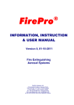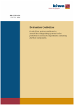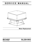
1
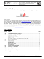
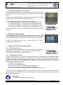
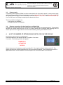
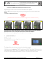
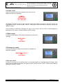
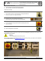
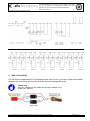
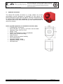
Information-, Instruction- and User manual af-x marine panel Version Datum : 04 : 04-08-2011 Keep this information, instruction and user manual for future use. This manual lapses when revised. The latest version is obtainable from af-x fire solutions. This information, instruction and user manual is part of the ASP (Aerosol Standard Procedure). Information, instruction and user manual Version-04 04-08-2011 af-x fire solutions® marine panel for activation of aerosol fire extinguishing systems in machinery spaces and pump rooms. This af-x marine panel is patented. Before you start. This instruction is a supplement of the Information-, Instruction- and User manual. The latest version can be found under ‘downloads’ on the website www.afxfiresolutions.com This Information, Instruction and User manual is part of the ASP (af-x fire solutions® standard procedure). For proper installation of the af-x fire solutions® systems, the user of this supplement needs to take note of the Information-, Instruction- and User manual. All instructions in this supplement as well as the Information-, Instruction- and User manual need to be followed accurately. Our manual can be consulted and/or downloaded via our website www.afxfiresolutions.com Table of contents Section 1.0 2.0 3.0 4.0 5.0 6.0 7.0 8.0 9.0 10.0 11.0 12.0 Subject Page af-x marine panel IMO-4, 8, 16 and 64 ............................................................................ 3 Display af-x marine panel ................................................................................................ 3 Connections of the af-x marine panel .............................................................................. 3 3.1 Remote control box .................................................................................................. 3 3.2 Potential free contacts .............................................................................................. 3 3.3 Power supply ........................................................................................................... 4 3.4 Remote connection for the signal horn and flash light .............................................. 4 Amount of extinguishers.................................................................................................. 4 Alarm on display ............................................................................................................. 5 5.1 Short circuit .............................................................................................................. 5 5.2 Open circuit .............................................................................................................. 6 5.3 Main supply .............................................................................................................. 6 5.4 Emergency supply.................................................................................................... 6 5.5 In case of fire ........................................................................................................... 6 Activating the fire extinguishers ....................................................................................... 7 Connections in marine panel ........................................................................................... 7 End of line diodes ........................................................................................................... 8 Sounder & Beacon .......................................................................................................... 9 Statement of conformity ................................................................................................ 10 Warranty, trademarks and patents ................................................................................ 10 Copyright ...................................................................................................................... 11 af-x fire solutions is the authorised distributor of the af-x fire extinguishing systems Page 2 of 11 Keep this information, instruction and user manual for future use. This manual lapses when revised. The latest version is obtainable from af-x fire solutions. This information, instruction and user manual is part of the ASP (Aerosol Standard Procedure). Information, instruction and user manual Version-04 04-08-2011 1. af-x marine panel IMO - 4, 8, 16 and 64 The high quality af-x marine panel is built to activate maximum 64 of the af-x aerosol extinguishers units placed in machinery spaces and pump rooms. The af-x marine panel is built in a stainless steel housing with certified components and is complying to the IMO regulations. The af-x marine panel can be ordered in different types: - af-x marine panel IMO-4 (to activate up to 4 extinguishers units) - af-x marine panel IMO-8 (to activate up to 8 extinguishers units) - af-x marine panel IMO-16 (to activate up to 16 extinguishers units) - af-x marine panel IMO-64 (to activate up to 64 extinguishers units) This marine panel may only be installed by CATTAS trained and certified persons. 2. Display af-x marine panels On every marine panel there is a display what is connected to the LOGO inside the panel. Whit this display you can operate the af-x marine panel and read several features. Further on this manual they will be handled. To show the software version of the control box push F1 and F4 simultaneously for 1 second. 3. Connections of the af-x marine panel: 3.1. Remote control box A remote control box (option) can be connected to the af-x marine panel clamps (see drawing page 6). The remote control box has the same functionality as the buttons on the marine panel. 3.2. Potential free contacts The af-x marine panel has 2 potential free contacts which can be connected to the XS4 clamps. Both contacts are normally closed contacts. This means in normal state the contacts are closed. The first potential free contact is for the incoming power supplies. If one of the two supplies is missing the contact will be open. The second potential free contact is the error indication. If one of the following faults occur the contact will be open: - main power supply missing; - emergency power supply missing; - short circuit in the wire of the connecting fire extinguisher; - open circuit in the wire of the connecting fire extinguisher; - if the door switch detects that the door of the af-x marine panel is open. If a fault occurs, the signal lamp “FAULT” and the buzzer “FAULT” will activate. The buzzer can be reset by pushing the “RESET” button. If another fault occurs and the previous fault was reset the buzzer will activate again. Please Note The potential free contact cannot be reset. af-x fire solutions is the authorised distributor of the af-x fire extinguishing systems Page 3 of 11 Keep this information, instruction and user manual for future use. This manual lapses when revised. The latest version is obtainable from af-x fire solutions. This information, instruction and user manual is part of the ASP (Aerosol Standard Procedure). Information, instruction and user manual Version-04 04-08-2011 3.3. Power supply 2 separate power supplies (24Vdc) must be connected to the af-x marine panel. A main power supply and emergency power supply are necessary to work properly. Wiring from the main power supply and emergency power supply, to the marine panel must be flexible 2 x 2,5 mm2 and fire resistant (E-30). If one of the power is missing the display will indicate this failure. The two possible messages are: - main power not available; - emergency power not available. 3.4. Remote connection for the signal horn and flash light A signal horn and flash light can be connected to the XS3 clamps (see drawing page 6). These signal devices will activate when the door of the af-x marine panel will be opened. After opening the af-x marine panel door the signal devices can be deactivated by pushing the “RESET” button. 4. A: SET UP NUMBER OF EXTINGUISHING UNITS LOGO ON THE DISPLAY! Programming the amount of extinguishers. Push the buttons on the display F2 and F3 together for at least 5 seconds. The following screen will appear: NUMBER OF ACTUATORS 4 F4 BACK Select the amount of actuators (units) by pushing F1. If the right number is choicen push F4. The display will show the voltage measurement of the connected actuators. The measurement current is approximate 4mA. So the resistance ore the length of the connected cable is not relevant. af-x fire solutions is the authorised distributor of the af-x fire extinguishing systems Page 4 of 11 Keep this information, instruction and user manual for future use. This manual lapses when revised. The latest version is obtainable from af-x fire solutions. This information, instruction and user manual is part of the ASP (Aerosol Standard Procedure). Version-04 04-08-2011 Information, instruction and user manual B: SET UP NUMBER OF EXTINGUISHING UNITS LOGO! Programming the number of units connected to the LOGO! in the cupboard Press the ESC button and hold it. Then press the (arrow left) button for 3 seconds. Release both buttons. The screen will display the following: NUMBER OF ACTUATORS 4 F4 BACK (the F4 back does not function now and is merely there for aesthetic reasons) Step 1 Step 2 Step 3 Step 4 Now press the ESC button again and hold it. Press the (arrow up) button until you have reached the appropriate number of units. Finally press the OK button to finalize the installation. After a few moments, the display will automatically show the measuring mode. 5. ALARMS ON DISPLAY 5.1 Short circuit If there is a short circuit in the cabling of the connector the display will show the message: SHORT CIRCUIT CABLE ACTUATOR [#] The display will also show the date and time when the problem emerged. If this fault occurs, the signal lamp “FAULT” and the buzzer “FAULT” will activate. The buzzer can be reset by pushing the “RESET” button. If the problem is solved the message will stay on the screen until the fault is acknowledged by pushing the “OK” button. The date and time will be loosed. af-x fire solutions is the authorised distributor of the af-x fire extinguishing systems Page 5 of 11 Keep this information, instruction and user manual for future use. This manual lapses when revised. The latest version is obtainable from af-x fire solutions. This information, instruction and user manual is part of the ASP (Aerosol Standard Procedure). Information, instruction and user manual Version-04 04-08-2011 5.2 Open circuit If there is a open circuit in the cabling of the connector the display will show the message: CABLE BREAKAGE ACTUATOR [#] ACT. WITH OK The display will also show the date and time when the problem emerged. If this fault occurs, the signal lamp “FAULT” and the buzzer “FAULT” will activate. The buzzer can be reset by pushing the “RESET” button. If the problem is solved the message will stay on the screen until the fault is acknowledged by pushing the “OK” button. The date and time will be loosed. 5.3 Main supply In case the main supply will fall away, the display will show the message: MAIN SUPPLY NOT AVAILABLE 5.4 Emergency supply In case the emergency supply will fall away, the display will show the message: EMERGENCY SUPPLY NOT AVAILABLE 5.5 In case of fire In case of fire open the af-x marine panel. A connected signal horn and flash light will activate. After opening the af-x marine panel door the signal devices and the buzzer “FAULT” can be deactivated by pushing the “RESET” button. af-x fire solutions is the authorised distributor of the af-x fire extinguishing systems Page 6 of 11 Keep this information, instruction and user manual for future use. This manual lapses when revised. The latest version is obtainable from af-x fire solutions. This information, instruction and user manual is part of the ASP (Aerosol Standard Procedure). Information, instruction and user manual Version-04 04-08-2011 6. ACTIVATING THE FIRE EXTINGUISHERS Follow the next steps: open de door of the af-x marine panel by turning the handle on 1. the door a quarter to the right (clockwise); 2. break the seal on the yellow/red rotary switch (see left lower part at the inside of the marine panel); turn the yellow/red rotary switch inside the marine panel to the 3. right (clockwise); 4. the fire extinguishers will activate. The message will stay on the screen until the fault is acknowledged by pushing the “OK” button. The date and time will be loosed. Warning The fire extinguishers can work only ones. After activation of the fire extinguishing system you must directly inform your dealer ore the distributer via +31 (0)186-699699 or via [email protected] 7. CONECTIONS IN MARINE PANEL af-x fire solutions is the authorised distributor of the af-x fire extinguishing systems Page 7 of 11 Keep this information, instruction and user manual for future use. This manual lapses when revised. The latest version is obtainable from af-x fire solutions. This information, instruction and user manual is part of the ASP (Aerosol Standard Procedure). Information, instruction and user manual 8. Version-04 04-08-2011 End of line diodes For the correct measurement of wire break an/ore short-circuit, you have to place two diodes between the end of the wire and the activator from the extinguishing unit. Please Note Ask your supplier ore the diodes are already installed or not. Diode type: 1N5062 af-x fire solutions is the authorised distributor of the af-x fire extinguishing systems Page 8 of 11 Keep this information, instruction and user manual for future use. This manual lapses when revised. The latest version is obtainable from af-x fire solutions. This information, instruction and user manual is part of the ASP (Aerosol Standard Procedure). Information, instruction and user manual 9. Version-04 04-08-2011 Sounder & Beacon The Nexus-105 sounder & beacon is a high output, low current consumption sounder designed for industrial, fire and marine use. During the tests we did use the Nexus-105 and recommend you to use the Nexus-105 with installation of our af-x marine panels. The Nexus-105 is IP66 what means that you can install the Nexus in almost any location. Nexus 105 dBA Industrial, Fire and Marine Sounder (Red) IP Rating IP66 / continuous Sound 105 dBA / 1m Version / 64 Tones / see tone table Operating Temp. -25ºC to +70ºC Weight 1.1Kg Quarter turn fasteners for ease of installation First fix, wire to base technology Cable Entries 5 Volume control for greater flexibility Three alarm stages Operating Voltage 10-60V Compliancy EN54-3 TYPE B VDS Approved af-x fire solutions is the authorised distributor of the af-x fire extinguishing systems Page 9 of 11 Keep this information, instruction and user manual for future use. This manual lapses when revised. The latest version is obtainable from af-x fire solutions. This information, instruction and user manual is part of the ASP (Aerosol Standard Procedure). Information, instruction and user manual Version-04 04-08-2011 10. Statement of conformity (II-A) We af-x fire solutions, herewith declare on our responsibility that the product af-x marine panel types IMO-4, IMO-8 and IMO-64, where to this statement refers, is in conformity to the RS “Rules for the Classification and Construction of Sea-Going Ships” (2010). and EMC directives 89/336/EEG and other normative documents following the definitions of the IMO regulations, BRL-23001/03 made up by KIWA Nederland. The BRL-23001/03 is also basis for the operating schedule Factory Production Control. The Netherlands, Oud-Beijerland, 1st January 2011. 11. Warranty manufacturer The manufacturer guarantee that the af-x marine panel used in the af-x fire solutions® installation perform consistent with the documentation, provided they are installed and maintained in accordance with the instructions. Liability Except for cases of deliberate or conscious recklessness by the Supplier or its employees, the Supplier excludes all liability for financial, consequential or other damage or loss on the User's side based on statements, guarantees (both explicit and implicit), conditions or other obligations by law. The same applies for unusual, indirect, incidental or consequential loss (including loss of profit or revenues, loss of documents or data, costs of substitute products, damage to reputation or goodwill, or any other matter that can reasonably be expected to be outside the Supplier’s power. User will not use product liability to lay claim with Supplier, but will, where it concerns a defect in the Products supplied by Supplier, hold the Manufacturer of Products directly responsible or refer to the Manufacturer. If User is held liable based on the legal product liability, there can never be any protection by Supplier. Manufacturer and Supplier cannot be held responsible for alterations to the Product made by User, nor for the consequences of those alterations. Trademarks Fire Solutions Benelux, af-x fire solutions, af-x marine panel, firepro are registered trademarks. All other company or product names are trademarks, registered trademarks or service brands of their respective owners. Patents af-x marine panel and FirePro® is a registered European patent. Legal action will be taken against violations of these patents, by whichever name. Information on guidelines / European guidelines Products with the CE-mark such as mentioned in this manual and in the Information-, Instruction- and User manual comply with both the guideline for stationary extinguishing components on dry aerosol basis (EMC directives 89/336/EEG) and the BRL-K23001. The accredited institute KIWA NV has certified FirePro® in accordance with this BRL (Assessment guideline). af-x fire solutions is the authorised distributor of the af-x fire extinguishing systems Page 10 of 11 Keep this information, instruction and user manual for future use. This manual lapses when revised. The latest version is obtainable from af-x fire solutions. This information, instruction and user manual is part of the ASP (Aerosol Standard Procedure). Information, instruction and user manual Version-04 04-08-2011 Authors : af-x fire solutions (Mr. R.G.C. Reijns) Sundermann Elektrotechniek (Mr. R.A. Sundermann) Basis : International Maritime Organisation, KIWA, TNO, KEMA Publisher : af-x fire solutions Benjamin Franklinstraat 14 3261 LW Oud-Beijerland Telephone : +31 (0)186-699699 Fax : +31 (0)186-699702 Home page: www.afxfiresolutions.com Email : [email protected] Layout : Conforms to NEN-5509 12. Copyright© All rights reserved. No part of this publication may be reproduced and/or published by print, photo print, microfilm or any other means without the prior permission of af-x fire solutions. If this manual is published under order, see the General Terms and Conditions of af-x fire solutions. or the relevant agreement concluded between the parties to this effect for the rights and obligations of customer and contractor. This manual may be given to directly interested parties for perusal. 2011 af-x fire solutions. The quality system of Fire Solutions Benelux B.V. / af-x fire solutions has been certified in accordance with ISO 9001:2008. af-x fire solutions is the authorised distributor of the af-x fire extinguishing systems Page 11 of 11