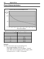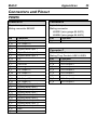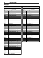
1
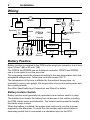
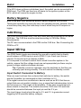
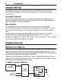
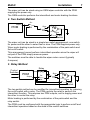
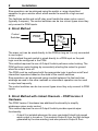
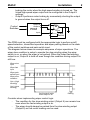
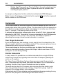
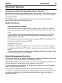
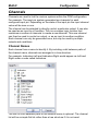
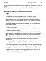
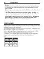
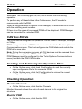
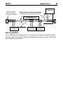
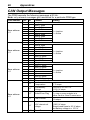
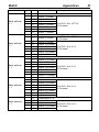
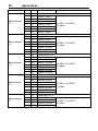
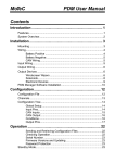
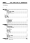
PDM Power Distribution Modules USER MANUAL MoTeC PDM User Manual Contents Introduction ........................................................................ 1 Features................................................................................................... 1 System Overview ..................................................................................... 2 Installation .......................................................................... 3 Mounting .................................................................................................. 3 Wiring....................................................................................................... 4 Battery Positive ............................................................................. 4 Battery Negative ............................................................................ 5 CAN Wiring .................................................................................... 5 Input Wiring.............................................................................................. 5 Output Wiring ........................................................................................... 6 Output Devices ........................................................................................ 6 Windscreen Wipers ....................................................................... 6 Solenoids ..................................................................................... 10 Electronic Devices ....................................................................... 11 PDM Manager Software Installation ...................................................... 12 Configuration.................................................................... 14 Configuration File .................................................................................. 14 Channels................................................................................................ 15 Configuration Tree ................................................................................. 16 Global Setup ................................................................................ 16 Input Pins..................................................................................... 17 CAN Inputs .................................................................................. 18 CAN Output ................................................................................. 19 Functions ..................................................................................... 20 Output Pins .................................................................................. 21 CAN Keypads .............................................................................. 26 Operation .......................................................................... 27 CAN Bus Bitrate .......................................................................... 27 Sending and Retrieving Configuration Files ................................ 27 Checking Operation..................................................................... 27 Serial Number ............................................................................. 28 Firmware Versions and Updating ................................................ 28 Password Protection ................................................................... 29 PDM User Manual Standby Mode........................................................................................ 29 Appendices ....................................................................... 30 Specifications......................................................................................... 30 CAN Input Channel Examples ............................................................... 32 Fuse Characteristics .............................................................................. 34 Connectors and Pinout .......................................................................... 35 PDM16......................................................................................... 35 PDM32......................................................................................... 36 PDM15......................................................................................... 38 PDM30......................................................................................... 39 Mounting Dimensions ............................................................................ 40 PDM16......................................................................................... 40 PDM32......................................................................................... 41 PDM15 and PDM30 .................................................................... 42 Wiring..................................................................................................... 43 Wire Specification ........................................................................ 43 UTC Wiring for PC Connection ................................................... 44 CAN Bus Wiring Requirements ................................................... 44 CAN Output Messages .......................................................................... 46 Windows Keyboard Shortcuts ............................................................... 52 Glossary................................................................................................. 56 Copyright 2014 – MoTeC Pty Ltd The information in this document is subject to change without notice. While every effort is taken to ensure correctness, no responsibility will be taken for the consequences of any inaccuracies or omissions in this manual. PN 63029 V3.3, February 2014 MoTeC Introduction 1 Introduction The PDMs replace conventional relays, fuses and circuit breakers by providing electronically switched power to the various electrical systems in the vehicle, including motors, lamps, ECUs and data systems. This simplifies wiring and switch requirements, while increasing reliability. There are four PDM versions: PDM16, PDM32, PDM15 and PDM30. Throughout this manual all versions will be referred to as the PDM except where details specific to a particular version are discussed. Features PDM16 PDM32 PDM15 PDM30 Inputs 12 23 16 16 8 Amp Outputs 8 24 7 22 20 Amp Outputs 8 8 8 8 Connectors Case size Length Width Height Autosport 130 mm 60 mm 28 mm 180 mm 60 mm 28 mm Waterproof connectors M6 stud 107 mm 133 mm 39 mm 107 mm 133 mm 39 mm Each output is over-current, short circuit and thermal overload protected Outputs are programmable in 1 A steps Outputs are controllable via a combination of switch inputs, CAN messages and logic functions Switch inputs are ranging from 0 to 51 V, resolution 0.2 V Performing up to 200 logic operations using operators like Flash, Pulse, Set/Reset, Hysteresis, Toggle, And, Or, Less than, Greater than, Not equal to, Equal to, True, False etc. Performing functions such as flashing indicator lights and controlling thermo fans and fuel pumps Using logic functions to selectively turn off systems during low battery voltage or engine starting, reducing drain on the battery 2 Introduction Providing full diagnostic information, including output currents and voltages, input voltages, and error status Transmitting diagnostic information via CAN to a display or data logging device or monitoring directly on a PC Protected against unauthorised access by a password feature. Accessories MoTeC UTC (USB to CAN adaptor) #61059 (Note: PDMs are not compatible with MoTeC CAN cable) System Overview – + Battery Battery Input Inputs Switches PDM CAN Outputs M M Motors CAN bus ECU Lights Other Devices MoTeC Installation 3 Installation Mounting When mounting the PDM take into account that the PDM may get very hot during operation. Ensure the PDM is mounted in a well ventilated area and not against a hot surface. For case dimensions see Mounting Dimensions. The internal temperature is highly dependent on ambient temperature and also on the total load current—a higher current will cause a higher temperature. Tip: The internal temperature can be checked in PDM Manager (see Operation) or transmitted via CAN to be logged. Allow for sufficient time for the temperature to stabilise. This may take 30 minutes or more. If the internal temperature of the PDM exceeds the specified maximum values (see Specifications), cooling may be achieved by one or more of the following: relocating the PDM to a cooler mounting position increasing air circulation around the PDM case ducting cool air over the PDM case fitting a heatsink to the back surface of the PDM case 4 Installation Wiring – + Battery Starter Motor Isolator Alternator M A Battery Input Switches Inputs PDM CAN CAN Connector for UTC 0V Outputs CAN Bus Keypad M M ECU Motors Lights Data Logger Other Devices Battery Positive Battery positive is supplied to the PDM via the single pin connector to suit wire sizes 16 mm2 (6#) or 25 mm2 (4#). The PDM16 and PDM32 use an Autosport connector, PDM15 and PDM30 use a 6 mm eyelet to suit the wire size. The wire gauge should be chosen according to the wire temperature limit and acceptable voltage drop. Tefzel wire must not exceed 150 °C. The temperature of the wire is affected by the ambient temperature, air circulation, current, wire gauge, the temperature of any surrounding wires and the covering sheath. See Wire Specification and Connectors and Pinout for details. Battery Isolator Switch Battery positive must generally be connected via an isolator switch or relay. The isolator must isolate the battery from all devices in the vehicle including the PDM, starter motor and alternator. The isolator must be rated to handle the starter motor current. When the battery is isolated, the engine may continue to run due to power supplied by the alternator. To avoid this, the isolator switch should have a secondary switch that is connected to a shutdown input on the ECU. MoTeC Installation 5 If the ECU does not have a shutdown input, the switch can be connected to a PDM input. The PDM can then turn off power to the ignition system or the ECU, which will cause the engine to stop. Battery Negative Both of the Batt– pins should be wired to battery negative via 20# wire. These pins normally only carry the very low operating current, however during a load dump they carry the load dump current which may be 50 ampere or higher. CAN Wiring The PDM communicates over CAN with other devices connected to the same CAN bus. The CAN bus must be wired according to CAN Bus Wiring Requirements. The PC also communicates to the PDM via the CAN bus. See Connecting the PDM to a PC. Input Wiring The PDM Switch Inputs are intended for use with a switch that is directly wired between a PDM input pin and a PDM 0 V pin. Each input has an internal 10 kilo-ohm pull-up resistor to Batt+. If it is required to connect a switch that is wired to another system in the vehicle, ensure that the voltage levels are set appropriately as there may be ground voltage variations between devices. Tip: If standby current is important, wire the switches so that they are normally open during standby. This will reduce the standby current. Input Switch Connected to Battery When an input is driven from a device that switches to battery, the switch should if possible, be rearranged so that it switches to 0 V. If the signal comes from an electronic device such as an ECU that has an output that can only switch to battery (e.g. a signal that indicates when to turn the fuel pump on), this might not be possible. In this case an external pulldown resistor is required. The resistor should be 1500 ohm 0.25 watt and should be connected between the input pin and the 0 V pin. The input trigger levels should be set to 4 V and 5 V to guarantee correct triggering for all possible battery voltages. 6 Installation Output Wiring All outputs are high side type outputs; they switch Batt+ to the output pin. They all have hardware thermal overload protection, fault logic and overcurrent logic. Paralleled Outputs Two or more output pins can be connected in parallel to increase current capacity. Outputs that are connected in parallel must all be of the same type; either all 8 Amp or all 20 Amp outputs. Wire Gauges The wire gauge must be chosen to suit the current consumed by the connected device and to ensure that the voltage drop is acceptable. On long runs it may be necessary to use a heavier gauge wire to minimise voltage drop. The wire gauge must also be compatible with the connector pin; using a smaller than recommended wire gauge may result in a poor crimp. Suitable wire gauges are 24# to 20# for the 8 Amp outputs and 20# to 16# for the 20 Amp outputs. See Wiring for details. Output Devices Windscreen Wipers The PDM can drive windscreen wiper motors; however the PDM cannot be connected to both the fast and slow motor windings at the same time. The voltage generated by the slow winding during fast operation will cause braking of the motor and possible damage to the PDM. A wiper unit can be wired in a number of ways. The following schematics are shown for 'common-ground' wiper units. For 'common-positive' wiper units the schematics must be adjusted accordingly. 1. OEM Controller Method Output S PDM OEM controller Control Switches M F Home Park Switch MoTeC Installation 7 The wiper unit can be wired using an OEM wiper controller with the PDM supplying the power only. The OEM controller performs the intermittent and motor braking functions. 2. Two Switch Method On Output PDM Slow Off S M c Fast F Home Park Switch The wiper unit can be wired in a simple two switch arrangement; one switch for power and the other to select fast or slow. The PDM supplies power only. Wiper motor braking is performed by the combination of the park switch and the on/off switch. This arrangement cannot perform intermittent operation since the wiper will not park if the PDM simply removes power. The switches must be able to handle the wiper motor current (typically 4 ampere). 3. Relay Method Relay Control Switches Output PDM Output Slow On Off S M Fast F Home Park Switch The two switch method can be modified for intermittent operation by replacing the on/off switch with a relay. The PDM controls the relay to perform the intermittent function. This requires two PDM outputs; one to supply power and the other to control the relay. Motor braking is performed by the combination of the park switch and the relay switch. The PDM must be configured with the appropriate logic to perform on/off and intermittent operation based on the state of the control switches. 8 Installation Slow operation can be achieved using the switch or using intermittent operation to give a similar effect which avoids the need for a high current switch. The fast/slow switch and on/off relay must handle the wiper motor current (typically 4 ampere). The control switches can be low current types since they only connect to PDM inputs. 4. Direct Method Output 9 Control Switches PDM S M Input F Home Park Switch The wiper unit can be wired directly to the PDM as long as it is only connected to one output. In this method the park switch is wired directly to a PDM input so the park logic must be configured in the PDM. This method requires the use of Output 9 which performs motor braking. The PDM performs motor braking by momentarily shorting the output to ground when the output turns off. The PDM must be configured with the appropriate logic to perform on/off and intermittent operation based on the state of the control switches. Slow operation can be achieved using a switch between the fast and slow windings as used in the other methods or intermittent operation can be used to wipe less frequently. The control switches can be low current types since they only connect to PDM inputs. 5. Direct Method with Linked Channels – PDM Version 2 Hardware The PDM Version 2 hardware has additional functionality to simplify windscreen wiper motor control. This method requires the use of Output 9 which provides special wiper functionality: - Output 9 is isolated whenever the user nominated linked high speed wiper output is turned on. This protects Output 9 from the high voltage generated by the slow winding, and also prevents Output 9 from MoTeC - Installation braking the motor when the high speed winding is turned on. The linked high speed wiper output can be configured in the Output 9 settings. Output 9 performs motor braking by momentarily shorting the output to ground when the output turns off. Control Switches Output 9 Output x PDM S M F Input Home Park Switch The PDM must be configured with the appropriate logic to perform on/off, speed selection, intermittent operation and wiper parking based on the state of the control switches and park switch input. The diagram below shows an example sequence of wiper operations. The wiper slow condition is setup to operate the slow winding when the wiper switch is on, or when the wiper is not parked. When the linked fast winding output is on, Output 9 is held off even though the condition driving output 9 is still true. Wiper slow input Wiper fast input Wiper park switch input Wiper slow condition Out x (High Winding) Out 9 (slow winding) Out 9 held off while linked output is on Parking Consider when implementing wiper control logic: - The condition for the slow winding output (Output 9) can remain true even when the fast winding output is on. - The wiper should always be parked from the slow winding output (Output 9) so that motor braking can be used. 9 10 Installation - Set the High Time and Low Time to 0.00s in the park switch input pin configuration so that the wiper is parked as soon as possible after reaching the park position. An sample configuration for this method is included with PDM Manager. Note: Version 2 hardware is indicated by the symbol 2 next to the engraved serial number on the PDM case. Solenoids The current drawn by a normal single coil solenoid ramps up from zero to its steady state value over a period of time. The time taken to do this depends on the inductance and resistance of the solenoid but is normally very short (less than 0.1 second). This has no effect on the PDM. A solenoid will generate a voltage spike when turned off; this is clamped and absorbed by the PDM. The amount of energy absorbed by the PDM depends on the inductance and current in the solenoid. The PDM is capable of absorbing the energy of most normal solenoids in a vehicle. Two Stage Solenoids Some solenoids have two windings; one is used to turn the solenoid on, the other is used to hold it on once it has switched. This ensures optimum turn on characteristics with minimum holding current. The current drawn by the turn on winding may be higher than the current drawn by the holding winding. Ensure the Output Load is well clear of 100% during turn on and during holding. Starter Solenoids In many cases it is possible to run starter solenoids from a single 20 Amp output even though they typically draw more than 20 ampere (possibly as much as 40 ampere). The Over-Current Shutdown feature allows excess current for a period of time. This feature will shut down the output after about 10 to 20 seconds of cranking. See the Over-Current Shutdown section for details. The wire can be rated for 20 ampere, also ensuring that the starter motor does not overheat during excess cranking. A larger wire gauge might be required if the voltage drop is not acceptable. Alternatively two 20 Amp outputs may be paralleled allowing cranking for any period of time (subject to overheating of the starter motor). MoTeC Installation 11 Electronic Devices The PDM can supply power to electronic devices such as engine management systems, data acquisition systems, radios etc. Many electronic devices will have a short inrush current. The PDM will largely ignore this due to the Output Load filtering. See the Over-Current Shutdown section for details. The PDM provides reverse battery protection and load dump clamping to protect itself and the connected devices. Ignition Systems Inductive Ignition Systems Most inductive ignition systems draw a peak current of about 8 ampere, some draw as much as 20 ampere; however the average current is much lower. In most cases inductive ignition systems can be connected to an 8 Amp output however the Output Load current must be checked to ensure it stays well clear of 100%. The average current will increase with increasing RPM so the Output Load should be checked at maximum RPM. CDI Ignition Systems CDI ignition systems can draw peak currents of as much as 50 ampere. It is recommended that all CDI ignition systems are connected to a 20 Amp output. The average current will increase with increasing RPM so the Output Load should be checked at maximum RPM. Engine Management Systems The current drawn by an engine management system will depend on the type of loads it is connected to and the operating conditions. Fuel injectors draw current in pulses. The maximum average current drawn by the fuel injectors is when they are at maximum duty cycle. For servo devices such as Drive by Wire motors maximum current is drawn when making large transitions. Check that the Output Load is clear of 100% under worst case operating conditions, i.e. when the injectors are operating at maximum duty cycle, servo devices are making large transitions and any auxiliary loads are drawing maximum current. 12 Installation CAN Keypads The CAN Keypads continuously communicate with the PDM which will prevent the PDM from entering its low power standby mode. Options for powering the keypads include: - Configuring the PDM to always power the keypads. This allows buttons on the keypads to be used for master startup functions, but the PDM would never enter standby mode. To minimize battery drain, the isolator would need to be turned off (eg. during vehicle transport or storage) - Wiring a master switch or ignition key input to the PDM. All outputs (including the keypad power) would be configured to turn off when the master switch or key is turned off. This allows the PDM to enter standby mode, minimizing battery drain. PDM Manager Software Installation The PDM Manager software is used to: Change the PDM configuration Monitor the PDM operation including the output currents and diagnostics Test the outputs by manually turning them off and on Set and unlock security password Update the firmware PC Requirements PDM Manager runs under Windows XP or Vista operating systems. The minimum recommended PC specification is a Pentium 90 with 16 MB RAM and a USB port. Installing PDM Manager Software Go to the MoTeC website at www.motec.com and navigate to downloads/software/latestreleases/PDM Manager software OR Locate PDM Manager software on the MoTeC Resource Disc Save the selected file in your preferred location (for example desktop) When downloading is finished, double click on the file and select run Follow the instructions on the InstallShield Wizard MoTeC Installation 13 To start the program after installation, click Start > All Programs > MoTeC > PDM Manager Updating PDM Manager Software Software updates are available to give access to the latest features. Download the latest software version from the website and follow the software installation instructions to update to the new version. To update the associated firmware in the device select Update Firmware from the Online menu. For more information refer to Operation. Connecting the PDM to a PC The PC communicates with the PDM via the CAN bus. The connection to the CAN bus is via USB through a MoTeC UTC. To connect through a UTC, a mating connector for the UTC must be wired to the PDM's CAN bus. Refer to UTC Wiring for PC Connection and CAN Bus Wiring Requirements for more information. The PC must connect to the PDM at the configured PDM CAN bitrate. Refer to the Operation section for details about CAN bitrate configuration. Note: The MoTeC CAN cable (#61021) cannot be used with the PDM. 14 Configuration Configuration The PDM requires various settings to be configured such as the maximum current settings for the outputs and the circumstances in which to turn the outputs on. The configuration settings are stored in a configuration file on the PC. Changes to the PDM configuration are performed ‘Offline’, i.e. without the PC communicating with the PDM. The changes are saved in the configuration file on the PC. The file must be sent to the PDM before the changes take effect. See Operation. Configuration File From the File menu the following options are available: New: creates a new configuration file Open: selects an existing configuration file Right-click the configuration file to Rename, Delete, Send to a disk etc. Close: closes the current configuration file Save: after a new configuration has been defined, it should be saved with a meaningful name Save as: can be used to create a copy of an existing configuration file by giving it a new name Check Channels: verifies that all channels are correctly generated Exit: exits the program To create a new configuration file On the File menu, click New. Select the PDM type and enter the Serial Number The serial number can be found on the PDM label This will open the Configuration Tree panel and the Channels panel. Tips: The most recently used files appear at the bottom of the File menu. This is often the easiest way to open an existing file. When changing the PDM type all configured inputs and outputs settings will be transferred to the relevant pin number in the new PDM type. Configuration files can be password protected, preventing unauthorised retrieving and sending of configuration files. MoTeC Configuration 15 Channels Channels are used to link the various systems within the PDM configuration. For example: The input pin system generates two channels for each configured input pin. Depending on the state of the input pin the input channel value will be zero or one. The channel can be selected to directly control a particular output. It can also be used as an input to a Condition. This is a complex logic function that combines a number of channels to create a new channel. This new channel can then be used to control an output, or as an input to another condition. Each channel can only be generated once, but may be used by multiple outputs and conditions. Channel Names Each channel has a name to identify it. By including a dot between parts of the channel name, channels are arranged in a tree structure. For example: Indicators.Left and Indicators.Right would appear as Left and Right under a node called Indicators. The use of a dot between parts of the channel name is optional. The channel list will be a simple flat list rather than a tree structure if it is not used. 16 Configuration To rename a channel globally Right-click on the channel name in the Channels window and click Rename. This will rename the channel where it is generated as well as in all the places where it is used. Configuration Tree The Configuration Tree is used to configure the Global Setup, Input Pins, CAN Inputs, Conditions, CAN Outputs, Keypad buttons and Output Pins. The input and output pins will be numbered according to the PDM type selected. Global Setup The Global Setup in the configuration tree is used to Enter the PDM type and serial number Configure the CAN addresses and timeout periods for incoming CAN messages Configure Master Retry and Master Shutdown channels for output pins Configure Keypad settings for CAN keypads PDM Type and Serial Number The PDM type (PDM32, PDM16 etc.) and serial number must be configured correctly before a new configuration file can be sent to a PDM. A configuration can only be sent to the matching PDM to ensure the correct configuration of PDMs in applications with multiple PDMs. Output Pins Master Retry The Master Retry feature turns all outputs that are in error back on. If there is still a fault on a particular output, this output will go into error again and will go through the normal retry sequence. To initiate a Master Retry by pressing a button Wire a button to a switch input Use the channel generated by this input as the trigger channel for the Master Retry. MoTeC Configuration 17 Output Pins Master Shutdown The Master Shutdown feature turns off all outputs that are configured for Master Shutdown, while a user configured channel is true. Any PDM channel can be used as the Master Shutdown channel. Each output pin can be individually configured to support or ignore the Master Shutdown channel. Keypads Up to four MoTeC CAN keypads can be configured to work with the PDM. The global keypad setup configures the overall keypad settings. Individual keypad buttons are configured under the Keypads in the Configuration Tree. The Keypad Name is a description of the keypad (eg. “Main Keypad”). The Keypad Type determines how many buttons will be shown in the keypad button configuration. The keypad Node ID and CAN Addresses must match the settings programmed into the keypad. Keypads are supplied by MoTeC preprogrammed with default settings for Keypad 1. The Restore Defaults button will select the default settings for the particular keypad. The Brightness Control settings allow the keypad backlight and LED brightness to be set to a specified level. An alternate brightness level and condition can be specified to allow day/night operation. Input Pins Configuration of an input will create a Status and a Voltage channel. Both channels can be used in a condition or to directly control an output. They are transmitted via CAN. To configure an Input Pin In the Configuration Tree, select Input Pins Double click the input to setup Type a channel name and select settings as required The trigger voltages are fully programmable. The recommended trigger voltages are approximately 3.5 V for the low threshold and 4.2 V for the high threshold. The high threshold should be set below 6 V to ensure detection of a high level signal when the battery voltage is low. To avoid switch bounce and/or to delay recognition when the switch changes state, the inputs also have programmable trigger times. A trigger time of 0.1 second will normally reject switch bounce. 18 Configuration Channel Name InputName InputName.Voltage Description Input Status 0 = Off 1 = On Voltage on the input Resolution 0.2 V CAN Output Yes Yes CAN Inputs The PDM can receive CAN messages allowing the outputs to be controlled by other devices. The PDM can be configured to receive CAN messages on up to seven different CAN addresses in the standard or extended address ranges. The CAN addresses and message timeout periods are configured in Global Setup in the Configuration Tree. To configure a CAN input In the Configuration Tree, select CAN Inputs On the Edit menu, click Add Type a channel name and select settings as required Channel extraction Channels are extracted from the CAN messages by specifying the CAN message and a byte offset within the message. Optional bit masking, byte swapping and dividing operations can be performed on the received channel, depending on the data size (8bit, 16bit signed or 16bit unsigned). 8 Bit Values An 8bit value is specified with a byte offset and an 8bit mask. To use the entire 8bit value, set the mask to FF (hex). 16 Bit Signed Values A 16bit signed value is specified with a byte offset (the first byte of the value within the CAN message), an optional byte swap, and a divisor (1 to 255). The resulting channel will be an 8 bit value with a range of 0 to 255. The PDM treats the received value as a signed 16 bit value (i.e. -32768 to 32767). Negative values are clamped to 0. If the value after division is greater than 255 then the result value will be clamped to 255. MoTeC Configuration 19 16 Bit Unsigned Values A 16bit unsigned value is specified with a byte offset (the first byte of the value within the CAN message), an optional byte swap, a 16bit mask, and a divisor (1 to 255). The resulting channel will be an 8 bit value with a range of 0 to 255. The PDM treats the received value as an unsigned 16 bit value (i.e. 0 to 65535). If the value after division is greater than 255 then the result value will be clamped to 255. Examples of the different types of CAN channel extraction are included in the Appendices. Timeout values If the CAN message is not received for a period exceeding its timeout period, the corresponding timeout channel will be set to TRUE. Each CAN input channel can be configured to hold its previous value or go to a specific value while the corresponding CAN message is timed out. Tip: The timeout channel can be used in a condition. Initial values If the channel is configured to hold the previous value when the CAN message times out then the channel will be set to zero on start-up. The channel stay zero until a matching CAN message is received. If the channel is configured to use a specific value when the CAN message times out then the channel will be set to this value on start-up. The channel stay at the timeout value until a matching CAN message is received. The PDM CAN bitrate is user configurable. All devices on the CAN bus must be set to the same speed. Refer to the Operation section for details about CAN bitrate configuration. CAN Output The PDM can transmit a set of fixed standard messages, and up to four user defined messages on the CAN bus. CAN messages are configured in Can Outputs in the Configuration Tree. The receiving device can use the messages for diagnostic purposes (particularly useful if the values are logged in a logging device), to show an alarm on a display, or to activate a feature in another device depending on the value of a PDM input switch. 20 Configuration The PDM CAN bitrate is user configurable. All devices on the CAN bus must be set to the same speed. Refer to the Operation section for details about CAN bitrate configuration. Standard Messages The sets of fixed messages to be sent from the PDM are configured in Standard Messages. Messages sets can be individually enabled and a base CAN address is configurable. Most MoTeC logging devices have CAN communications templates available to receive these messages. The transmitted CAN messages include Output Voltage, Output Current, Output Load, Output Status, Input State, Internal Temperature, Battery Voltage, Global Error, and Total Current. See CAN Output Messages in the Appendices for details on the CAN messages. Standard messages are transmitted at 20Hz. User Defined Messages Up to four user defined CAN messages to be sent from the PDM can be configured in Message 0 to Message 3. Up to 8 channels can be included in each CAN message, with one channel per message byte. The CAN address is user configurable in the standard or extended address ranges. User defined messages are transmitted at 50Hz. Functions Conditions A condition is a complex logic function that combines a number of channels to create a new channel. The logic operations include AND, OR, flash and many more. The new channel, with a value of either TRUE (1) or FALSE (0), can be used to directly control an output or it can be used in another condition. Counters A counter generates an integer channel value that can be incremented or decremented on transitions of other logic channels. Number of Operations There are a total of 200 logic operations available in the PDM. The number of operations used is shown in the status line. MoTeC Configuration 21 Tip: A condition can also be configured in the output pin setup. In this case the outcome of the logic function will not create a new channel but will be directly connected to the output channel. To configure a Condition or Counter In the Configuration Tree, select Functions On the Edit menu, click Add Select the function type (Counter or Condition) Type a channel name and select settings as required Output Pins All outputs are high side type outputs; they switch Batt+ to the output pin. All outputs have hardware thermal overload protection, fault logic and overcurrent logic. Paralleled Outputs When two or more output pins are connected in parallel, they must be configured to use a common channel or an identical condition to activate them. Note: outputs that are connected in parallel must all be of the same type; either all 8 Amp or all 20 Amp outputs. Output Protection Over-Current Shutdown An Over-Current Shutdown occurs when the Output Load exceeds 100%, which corresponds to the maximum current setting. The Output Load value is filtered so that it normally increases (and decreases) slowly, modelling how the temperature of a wire responds to the current flowing through it. The resultant characteristic is very similar to a thermal circuit breaker which is often used in motorsport applications. It is also similar to a slow blow fuse. See Fuse Characteristics for details. The filtering of the load value ensures that the start-up current (inrush current) of motors and lamps does not cause the output to shutdown during this period. It also allows for short term overloads to occur without the output shutting down. A large over-current such as a short circuit will cause the Output Load value to increase rapidly, causing the output to shutdown in a short period of time to protect the wire and the PDM output. The filtering is set with a time constant of 20 to 50 seconds based on the maximum current setting. These values conservatively suit the appropriate wire gauge for the 22 Configuration selected current setting and are not adjustable. Tips: The Output Load and Output Current values are transmitted via CAN so that they can be logged by another device. Check the logged Output Load value to ensure it is not too close to 100% during normal operation and during start-up. The Output Load and Output Current values can also be monitored using PDM Manager. See Checking Operation. Fault Shutdown A Fault Shutdown occurs when the output voltage is lower than expected. This can be caused by a short circuit or thermal overload of the output. A short circuit may cause a Fault Shutdown before the Over-Current Shutdown occurs. Output Settings To configure an Output Pin In the Configuration Tree, select Output Pins Double click the output to setup Type a channel name and select settings as required Maximum Current This sets the current at which the output will shutdown. The output current may exceed this value for a period of time which allows for the start-up (inrush) current of devices such as motors and lamps. The maximum current can be set to 10 ampere on the 8 Amp outputs and 25 ampere on the 20 Amp outputs to be clear of the normal running current, even for devices that draw the maximum specified current of 8 or 20 ampere. Number of Retries and Retry Delay When an Over-Current Shutdown or a Fault Shutdown occurs, the PDM will attempt to turn the output on again if the Number of Retries is configured. The Number of Retries determines how many times an output will attempt to turn on again. The Retry Delay determines how long an output remains shutdown before it is turned on again. The retry count for an output is reset whenever the condition driving the output changes to FALSE and then to TRUE (i.e. when the condition MoTeC Configuration 23 driving the output turns off then on again). Master Shutdown If Master Shutdown is enabled on the output, the output will be turned off while the Master Shutdown channel is true. The Master Shutdown channel is configured in the Global Setup. Stay Alive During Standby Mode Up to four outputs can be configured to stay alive (i.e. remain turned on) during the PDM low power standby mode. Refer to the Standby Mode section for more information. Linked High Speed Wiper Output (For output 9 only) The PDM Version 2 hardware has additional functionality to simplify windscreen wiper motor control. Linked output control can be enabled and a linked channel can be selected in the settings for Output 9. If this setting is enabled then Output 9 will be held off while the linked channel used for the high speed wiper winding is turned on. See the Windscreen Wipers section for more detail. Tips: There is a Master Retry feature available in Global Setup Ensure that the maximum current has been set appropriately by checking that the Output Load value is less than 100% under all operating conditions. The wire used must be capable of carrying the current specified in the maximum current setting. See Wire Specification. Set the maximum current well clear of the normal operating current of the device but within the current rating of the wire. Use a larger wire to achieve this if necessary. For example, for a device that draws no more than 5 ampere (except at start-up) use a wire that is rated at 8 ampere and set the maximum current to 8 ampere to give a clear margin. Consider the voltage drop of the wire when selecting the wire size. Sometimes this dictates that a larger wire gauge is needed than the current rating would suggest. Setting the current close to the normal current of the device to try and protect the device is unlikely to be effective and could result in an inadvertent shutdown. The purpose of the maximum current setting is 24 Configuration to protect the wire from overheating, not to protect the connected device. Some devices draw more current under circumstances such as high or low battery voltage. Also, a motor will draw increased current when under more load. Set a good margin and where possible check the Output Load value under these varying circumstances. Configuration of an output will create a number of channels, some of which are transmitted via CAN. OutputName.Status channel is used for output status information on CAN. The output should be on for any non-zero value. Channel Name Description OutputName Output Control Status 0 = Off 1 = On (Note: the output may be off due to Over-current Shutdown or Fault Shutdown) Voltage on the output Resolution 0.2 V Output Current in amps Resolution 0.5 A on Outputs 1 – 8 Resolution 0.2 A on Outputs 9 – 32 Output Load. Filtered current as a percentage of the maximum current setting. Resolution 1% 0 = Off 1 = On Active 2 = Over-Current Shutdown 4 = Fault Shutdown 0 = Output is off 1 = Output is on 0 = OK 1 = Over-Current Shutdown 0 = OK 1 = Fault Shutdown OutputName.Voltage OutputName.Current OutputName.Load OutputName.Status OutputName.Status. Active OutputName.Status. OverCurrent OutputName.Status. Fault CAN Output No Yes Yes Yes Yes No No No Fault Indicator When an output fault occurs the PDM sets the value of the Global Error channel to TRUE (PDM.Global Error). A fault indicator light can be connected MoTeC Configuration 25 to any PDM output and configured to turn on when the Global Error channel is TRUE. The Global Error channel can also be transmitted via CAN to a display device and used to show an alarm message and activate an alarm light. Maximum Current for Typical Output Devices Lamps Tungsten Lamps Typically used for tail lights, indicator lights and general lighting. Tungsten lamps draw additional current during turn on. Typically this peaks at about 5 times the steady state current and dies out in about 0.1 second. The PDM will largely ignore this due to the Output Load filtering. Halogen Lamps Halogen lamps are commonly used in headlights and are more efficient than Tungsten lamps. Halogen lamps have similar characteristics to Tungsten lamps. Xenon (HID) Lamps Xenon lamps are also used in headlights and are more efficient than Tungsten and Halogen lamps. Xenon lamps have a long duration inrush current that peaks at about 4 times the steady state current. The inrush current decays over a period of about 10 seconds. This puts a high load on the PDM output during startup. To avoid Over-Current Shutdown during start-up it may be necessary to set a higher Maximum Current than normal particularly if the battery voltage is low. For example, a Xenon lamp with a steady state current of 3 ampere may need a Maximum Current setting of 6 to 8 ampere. The wire should also be rated at this current. Unlike other lamps, Xenon lamps draw more current as the battery voltage decreases. At 10 volt the lamp will draw 40% more current than at 14 volt. For example a lamp that draws 3 ampere at 14 volt will draw 4.2 ampere at 10 volt. This must be allowed for when setting the Maximum Current. To ensure that the Maximum Current is set appropriately, check that the Output Load value stays safely below 100% during turn on when the battery is at 12 volt (not charging). 26 Configuration Motors Electric motors draw additional current during start-up. Typically the startup current is 3 to 5 times the steady state current and it dies out in less than a second. This start-up current is largely ignored by the PDM due to the Output Load filtering. The current in a motor increases with increasing load on the motor. A motor draws maximum current when it is stalled. The Maximum Current setting should take this into account. A motor may draw more current as it or the device that it is connected to ages; this should be allowed for when setting the Maximum Current. Note: motor speed control is currently not supported. CAN Keypads Up to four MoTeC CAN keypads can be configured to work with the PDM. A keypad must be enabled and configured under the Global Settings before the individual buttons can be configured. To use a keypad button, a channel name must be specified. This channel will be true while the keypad button is pressed. Each of the three LEDs on a keypad button can be controlled with a PDM channel. The LED will be turned on while the channel is true. A maximum of 120 keypad LEDs (across all keypads) can be configured. Keypad button numbering is from left to right, from top to bottom. E.g. 1 2 3 4 5 6 7 8 9 10 11 12 13 14 15 MoTeC Operation 27 Operation CAUTION: The PDM may get very hot, do not touch the PDM during operation. To perform any of the activities in the Online menu, the PC needs to communicate with the PDM. When a configuration file is open in PDM Manager, it will connect to the PDM with the matching serial number. If there is no file open, all connected PDMs will be displayed. PDM Manager can be connected to a selected PDM. CAN Bus Bitrate The PDM can be configured to operate at CAN bit rates of 250Kbps, 500Kbps or 1Mbps. PDM manager includes a CAN bitrate conversion tool in the Tools > Options > Communications menu. This tool configures the CAN bitrate and restarts the PDM at the new rate. Note: During the conversion process, all CAN devices must be removed from the CAN bus except for the PDM and the UTC. PDM Manager must be configured (in the Tools>Options>Communications menu) to match the PDM CAN bit rate. Sending and Retrieving Configuration Files On the Online menu, click Send Configuration to send the currently open configuration file to the connected PDM On the Online menu, click Get Configuration to retrieve the current configuration file in the connected PDM Checking Operation Monitor Channels On the Online menu, click Monitor Channels Monitor Channels shows the value of each channel in the original tree structure. Monitor PDM On the Online menu, click Monitor PDM 28 Operation Monitor PDM shows the input-, output-, CAN input-, condition- and PDM status channels in separate screen areas in an easy to view layout. Test Outputs On the Online menu, click Test Outputs All outputs may be manually turned on and off in PDM Manager to check the current levels. To be able to test an output, it must first be configured in PDM Manager. Serial Number On the Online menu, click Show Serial Number A configuration file can only be sent to the PDM with the matching serial number. This allows multiple PDMs to be used without special device configuration requirements and also ensures that each PDM has the correct configuration file. Firmware Versions and Updating On the Online menu, click Update Firmware The software inside the PDM (firmware) can be updated by the user at any time to take advantage of the latest features. Matching Versions The firmware version must match the version of the PDM Manager software on the PC in order to communicate. PDM Manager will show a warning if the versions do not match. Tip: To check the version of PDM Manager software, click About MoTeC PDM Manager on the Help menu. To check the firmware version in the PDM click Show Serial Number on the Online menu Matching Configuration File Configuration files created with new software including new features can not be used with older version of the software. If required, create backup files before updating. MoTeC Operation 29 Password Protection On the Online menu, click Set Password The password will prevent unauthorised retrieving and sending of configuration files. It is not possible to update firmware if the PDM is password protected. Standby Mode The PDM has a low power standby mode to minimize battery drain when the vehicle is turned off. Up to four outputs can be configured in the Output Pin settings to stay alive (i.e. remain turned on) during the standby mode. These outputs are intended for powering applications where electronic devices require a continuous low current (typically micro amps) supply to maintain settings or state. The PDM enters the low current Standby Mode when all of the following conditions have been true for 5 minutes: - All outputs that do not have the “stay alive during standby mode” option enabled are turned off - All outputs that have the “stay alive during standby mode” option enabled are below the allowed current limits (approximately 0.5A) - No CAN messages have been received - No CAN messages have been successfully transmitted The PDM will exit the Standby Mode when any of the following conditions are true: - Activity is present on the CAN bus - Any output that has the “stay alive during standby mode” option enabled exceeds the allowed current limit (approximately 0.5A) - Any input pin changes state 30 Appendices Appendices Specifications General Battery voltage Current consumption Total output current (continuous) Reverse battery protection Load dump transient protection Operating temperature Weight Length Width Height Case Environmental protection 30 V max, 6.5 V min 35 mA typical operating 5 mA typical standby PDM16 PDM32 PDM15 PDM30 100 A 120 A 80 A 100 A Protection for PDM and all connected devices Protection for PDM. Also assists in protecting connected devices. 110 °C max internal (100 °C recommended) Typical 85 °C max ambient for 120 A total load (for 110 °C internal) depending on mounting, air circulation and load distribution. These specifications apply for a 12 V battery. For a 24 V battery reduce specified temperatures by 20 °C. PDM16 PDM32 PDM15 PDM30 405 g 260 g 270 g 330 g (0.72 lbs) (0.89 lbs) (0.57 lbs) (0.59 lbs) 180 mm 107 mm 107 mm 130 mm (5.1") (7.1") (4.2") (4.2") 60 mm 60 mm 133 mm 133 mm (2.4") (2.4") (5.2") (5.2") 28 mm 39 mm 39 mm 28 mm (1.1") (1.1") (1.5") (1.5") Machined aluminium Magnesium Rubber seal on lid and Conformal coating on connectors, conformal PCB coating on PCB MoTeC Appendices 31 20 Amp Outputs Number of 20 A outputs Maximum output current Over-current shutdown Protection Inductive load clamp voltage Maximum inductive load energy PDM16 PDM32 PDM15 PDM30 8 8 8 8 20 A continuous, 115 A transient (typical) Programmable in steps of 1 A Short circuit and thermal overload protection –17 V (relative to Batt–) 1.5 J (junction temperature = 150 °C, load current = 20 A) 8 Amp Outputs Number of 8 A outputs Maximum output current Over-current shutdown Protection Inductive load clamp voltage Maximum inductive load energy PDM16 PDM32 PDM15 PDM30 8 24 7 22 8 A continuous, 60 A transient (typical) Programmable in steps of 1 A Short circuit and thermal overload protection Output 9: –0.7 V (relative to Batt–) Other Outputs: –42 V (relative to Batt+) 0.3 J (junction temperature = 150 °C, load current = 20 A) Inputs Number of inputs Pull-up resistor Measurement Calibration PDM16 PDM32 PDM15 PDM30 12 23 16 16 10 kilo ohm to Batt+ Range of 0 to 51 V, resolution 0.2 V (8 bits) High and low trigger voltage, high and low trigger times CAN Input Number of messages 4 messages, 8 bytes per message CAN Output Message rate 20 Hz 32 Appendices CAN Input Channel Examples Sample received CAN message used in examples below Byte Value (hex) 0 00 1 00 2 F3 3 21 4 40 5 00 6 CC 7 8A Channel Extraction Examples Offset Data Size Mask Byte 2 8bit FF Resulting channel: 0xF3 masked with 0xFF = 0xF3 Offset Data Size Mask Byte 2 8bit 02 Resulting channel: 0xF3 masked with 0x02 = 0x02 Offset Data Size Alignment Byte 3 16bit (signed) Normal Resulting channel: 0x2140 / 100 = 85 Divisor 100 Offset Data Size Alignment Byte 3 16bit (signed) Swap Bytes Resulting channel: 0x4021 / 100 = 164 Divisor 100 Offset Data Size Alignment Divisor Byte 2 16bit (signed) Normal 100 Resulting channel: 0xF321 is negative (-3295) so channel is clamped to 0 Offset Data Size Alignment Mask Divisor Byte 6 16bit (unsigned) Swap Bytes 0FFF 25 Resulting channel: (0x8ACC masked with 0x0FFF) / 25 = 110 MoTeC Appendices 33 Offset Data Size Alignment Mask Divisor Byte 6 16bit (unsigned) Normal FFFF 100 Resulting channel: (0xCC8A masked with 0x0FFF) / 100 = 523 so channel is clamped to 255 Typical CAN input channel application A CAN message contains a 16 bit RPM value with resolution of 1 RPM. Using a 16bit unsigned data type and a divider of 100 gives a resulting channel with a resolution of 100 RPM. The maximum channel value of 255 will be equivalent to 25500 RPM. The resulting channel can be used in conditions to turn outputs on when the RPM is above or below preset limits. 34 Appendices Fuse Characteristics Trip time versus over current multiplier at 10A 100.00 Trip time (s) 10.00 1.00 0.10 1 2 3 Max current setting [A] 4 5 6 7 Over current multiplier 8 9 Trip time multiplier 4 76% 6 84% 8 92% 10 100% 15 120% 20 140% Example: For 25 A current where max current setting is 5 A: Over current multiplier: 25 A / 5 A = 5 From Graph: Trip time (at 10 A) is approx. 1 second From Table: Trip time multiplier (at 5 A) is approx. 80% Trip time (at 5 A) = 1 x 80% = 0.8 seconds 10 MoTeC Appendices 35 Connectors and Pinout PDM16 Connector A 26 pin Autosport Mating connector #65040 Connector B 1 pin Autosport Mating connector #68093 (wire gauge #6 AWG) #68094 (wire gauge #4 AWG) Pin Function Pin Function A_A A_B A_C 8 A Output 9 8 A Output 10 8 A Output 11 B_1 Batt+ A_D Digital/Switch Input 1 A_E Digital/Switch Input 2 A_F Digital/Switch Input 3 Connector C 8 Pin Autosport Mating Plug: Deutsch AS616-08SN A_G A_H A_J A_K A_L A_M A_N A_P A_R A_S A_T A_U A_V A_W A_X A_Y A_Z A_a A_b A_c 0V 0V CAN Low CAN High 8 A Output 12 8 A Output 13 8 A Output 14 8 A Output 15 8 A Output 16 Digital/Switch Input 4 Digital/Switch Input 5 Digital/Switch Input 6 Digital/Switch Input 7 Digital/Switch Input 8 Digital/Switch Input 9 Digital/Switch Input 10 Digital/Switch Input 11 Digital/Switch Input 12 Batt– Batt– Pin Function C_A C_B C_C C_D C_E C_F C_G C_H 20 A Output 1 20 A Output 2 20 A Output 3 20 A Output 4 20 A Output 5 20 A Output 6 20 A Output 7 20 A Output 8 36 Appendices PDM32 Connector A 37 pin Autosport Mating connector #68089 Pin Function A_1 A_2 A_3 A_4 A_5 A_6 A_7 A_8 A_9 A_10 A_11 A_12 A_13 A_14 A_15 A_16 A_17 A_18 A_19 A_20 A_21 A_22 A_23 A_24 A_25 A_26 A_27 A_28 A_29 A_30 A_31 A_32 A_33 A_34 A_35 A_36 A_37 Digital/Switch Input 1 Digital/Switch Input 2 Digital/Switch Input 3 Digital/Switch Input 4 Digital/Switch Input 5 0V 0V 0V 0V CAN Low CAN High Digital/Switch Input 6 Digital/Switch Input 7 Digital/Switch Input 8 Digital/Switch Input 9 Digital/Switch Input 10 Digital/Switch Input 11 Digital/Switch Input 12 Digital/Switch Input 13 Digital/Switch Input 14 Digital/Switch Input 15 0V 0V 0V 0V Digital/Switch Input 16 Digital/Switch Input 17 Digital/Switch Input 18 Digital/Switch Input 19 Digital/Switch Input 20 Digital/Switch Input 21 Digital/Switch Input 22 Digital/Switch Input 23 Not Connected Not Connected Not Connected Not Connected Connector B 26 pin Autosport Mating connector #65040 Pin Function B_A B_B B_C B_D B_E B_F B_G B_H B_J B_K B_L B_M B_N B_P B_R B_S B_T B_U B_V B_W B_X B_Y B_Z B_a B_b B_c 8 A Output 9 8 A Output 10 8 A Output 11 8 A Output 12 8 A Output 13 8 A Output 14 8 A Output 15 8 A Output 16 8 A Output 17 8 A Output 18 8 A Output 19 8 A Output 20 8 A Output 21 8 A Output 22 8 A Output 23 8 A Output 24 8 A Output 25 8 A Output 26 8 A Output 27 8 A Output 28 8 A Output 29 8 A Output 30 8 A Output 31 8 A Output 32 Batt– Batt– MoTeC Appendices PDM32 continued Connector C 1 pin Autosport Mating connector #68093 (wire gauge #6 AWG) #68094 (wire gauge #4 AWG) Pin Function C_1 Batt+ Connector D 8 pin Autosport Mating connector #68092 Pin Function D_A D_B D_C D_D D_E D_F D_G D_H 20 A Output 1 20 A Output 2 20 A Output 3 20 A Output 4 20 A Output 5 20 A Output 6 20 A Output 7 20 A Output 8 37 38 Appendices PDM15 Connector A 34 pin waterproof connector Mating connector #65044 Connector B 26 pin waterproof connector Mating connector #65045 Pin Function Pin Function A_1 A_2 A_3 A_4 A_5 A_6 A_7 A_8 A_9 A_10 A_11 A_12 A_13 A_14 A_15 A_16 A_17 A_18 A_19 A_20 A_21 A_22 A_23 A_24 A_25 A_26 A_27 A_28 A_29 A_30 A_31 A_32 A_33 A_34 20 A Output 1 (with A10) 8 A Output 9 20 A Output 2 (with A12) 8 A Output 10 20 A Output 3 (with A14) 8 A Output 11 20 A Output 4 (with A16) 8 A Output 12 20 A Output 5 (with A17) 20 A Output 1 (with A1) 8 A Output 13 20 A Output 2 (with A3) 8 A Output 14 20 A Output 3 (with A5) 8 A Output 15 20 A Output 4 (with A7) 20 A Output 5 (with A9) Not used Digital/Switch Input 2 Not used Digital/Switch Input 4 Not used Digital/Switch Input 7 Not used Not used Battery Negative Digital/Switch Input 1 0V Digital/Switch Input 3 Digital/Switch Input 5 Digital/Switch Input 6 Digital/Switch Input 8 Digital/Switch Input 9 Digital/Switch Input 10 B_1 B_2 B_3 B_4 B_5 B_6 B_7 B_8 B_9 B_10 B_11 B_12 B_13 B_14 B_15 B_16 B_17 B_18 B_19 B_20 B_21 B_22 B_23 B_24 B_25 B_26 Not used Not used 20 A Output 6 (with B9) Not used 20 A Output 7 (with B11) Not used 20 A Output 8 (with B13) Not used 20 A Output 6 (with B3) Not used 20 A Output 7 (with B5) Not used 20 A Output 8 (with B7) Not used Digital/Switch Input 13 Not used Digital/Switch Input 15 Battery Negative Not used Digital/Switch Input 11 Digital/Switch Input 12 0V Digital/Switch Input 14 Digital/Switch Input 16 CAN Low CAN High Connector C M6 stud Mating: eyelet and M6 nut Pin Function C_1 Battery + MoTeC Appendices PDM30 Connector A 34 pin waterproof connector Mating connector #65044 Connector B 26 pin waterproof connector Mating connector #65045 Pin Function Pin Function A_1 A_2 A_3 A_4 A_5 A_6 A_7 A_8 A_9 A_10 A_11 A_12 A_13 A_14 A_15 A_16 A_17 A_18 A_19 A_20 A_21 A_22 A_23 A_24 A_25 A_26 A_27 A_28 A_29 A_30 A_31 A_32 A_33 A_34 20 A Output 1 (with A10) 8 A Output 9 20 A Output 2 (with A12) 8 A Output 10 20 A Output 3 (with A14) 8 A Output 11 20 A Output 4 (with A16) 8 A Output 12 20 A Output 5 (with A17) 20 A Output 1 (with A1) 8 A Output 13 20 A Output 2 (with A3) 8 A Output 14 20 A Output 3 (with A5) 8 A Output 15 20 A Output 4 (with A7) 20 A Output 5 (with A9) 8 A Output 16 Digital/Switch Input 2 8 A Output 17 Digital/Switch Input 4 8 A Output 18 Digital/Switch Input 7 8 A Output 19 8 A Output 20 Battery Negative Digital/Switch Input 1 0V Digital/Switch Input 3 Digital/Switch Input 5 Digital/Switch Input 6 Digital/Switch Input 8 Digital/Switch Input 9 Digital/Switch Input 10 B_1 B_2 B-3 B_4 B-5 B_6 B_7 B_8 B_9 B_10 B_11 B_12 B_13 B_14 B_15 B_16 B_17 B_18 B_19 B_20 B_21 B_22 B_23 B_24 B_25 B_26 8 A Output 21 8 A Output 22 20 A Output 6 (with B9) 8 A Output 23 20 A Output 7 (with B11) 8 A Output 24 20 A Output 8 (with B13) 8 A Output 25 20 A Output 6 (with B3) 8 A Output 26 20 A Output 7 (with B5) 8 A Output 27 20 A Output 8 (with B7) 8 A Output 28 Digital/Switch Input 13 8 A Output 29 Digital/Switch Input 15 Battery Negative 8 A Output 30 Digital/Switch Input 11 Digital/Switch Input 12 0V Digital/Switch Input 14 Digital/Switch Input 16 CAN Low CAN High Connector C M6 stud Mating: eyelet and M6 nut Pin Function C_1 Battery + 39 40 Appendices Mounting Dimensions PDM16 MoTeC PDM32 Appendices 41 42 Appendices PDM15 and PDM30 MoTeC Appendices 43 Wiring Wire Specification M22759/16 Insulation Material: Tefzel Conductor: Tin Plated Copper Voltage Rating: 600 V Maximum Temperature: 150 C Wire Current Rating Current Rating Resistance Resistance Gauge at 80 °C ambient at 100 °C ambient [ohm/m] [ohm/1000 ft] (AWG) [A]* [A]* 24# 4.5 4 0.071 22 22# 6 5 0.045 14 20# 8 6 0.028 8.5 18# 11 9 0.018 5.5 16# 15 12 0.014 4.3 14# 22 18 0.009 2.7 6# 90‡ 75‡ 0.0015 0.44 4# 120‡ 100‡ 0.0009 0.28 2# 150‡ 120‡ 0.0006 0.18 *The current ratings above are an indication only and will not apply in all circumstances. The actual maximum current rating is determined by the maximum allowed temperature for the wire (150 °C). The temperature of the wire is affected by many factors including the temperature of adjacent wires, how the wires are bundled and covered, the ambient temperature and the current. ‡current rating for a single wire in free air Recommended Wire Gauge Output 24# to 20# 8 Amp outputs 20# to 16# 20 Amp outputs 4# to 2# Battery pos 44 Appendices UTC Wiring for PC Connection To connect to a PDM through a MoTeC UTC (USB to CAN adaptor), a mating connector for the UTC must be wired to the PDM's CAN bus. The UTC connects to the PC USB port with a standard USB A-B cable. If the PDM does not connect to any other CAN device, it can be directly wired to the CAN connector. If the wiring length is less than 2 m (7 ft) the terminating resistor is recommended but not essential as the UTC has a built in terminating resistor. CAN Connector (5 pin XLR Female) 1 2 3 4 5 PDM Black 9 Green White Green White 10 11 0V CAN-LO CAN-HI These wires must be twisted Minimum one twist per 50 mm (2 in) 100R Resistor *Not essential if the wiring length is less than 2 m (7 ft) UTC Connector Type (5 pin XLR Female): Deltron Neutrik 716-0-0501 NC5FDL1 (Non-latching) (Latching) CAN Bus Wiring Requirements The CAN bus should consist of a twisted pair trunk with 100R (0.25 watt) terminating resistors at each end of the trunk. The preferred cable for the trunk is 100R data cable but twisted 22# Tefzel is usually OK. The maximum length of the bus is 16 m (50 ft) CAN devices (such as MoTeC PDM, M800 etc) may be connected to the trunk with up to 500 mm (20 in) of twisted wire. The CAN Connector for the UTC may also be connected to the trunk with up to 500mm (20in) of twisted wire and should be within 500mm of one end of the trunk. If desired two CAN connectors may be used so that the UTC may be connected to either side of the vehicle. Both connectors must be within 500mm of each end of the trunk. MoTeC Appendices 45 UTC Connector 500 mm Max CAN-HI CAN-LO CAN Device eg ADL3 CAN Device eg M1 ECU 0V CAN-HI CAN-LO 500 mm max CAN-HI CAN-LO CAN-HI CAN-LO 100R 100R << CAN Bus >> 5 4 Minimum one twist per 50 mm (2 in) 1 These wires must be twisted CAN-HI CAN-LO 100R Terminating Resistors at each end of the CAN Bus CAN Device eg PDM Short CAN Bus If the CAN Bus is less than 2 m (7 ft) long then a single termination resistor may be used. The resistor should be placed at the opposite end of the CAN bus to the CAN connector. 46 Appendices CAN Output Messages The PDM transmits the following messages at 20 Hz. Note: only relevant messages get transmitted for a particular PDM type CAN Address Byte Bit Base address +0 Base address +0 Base address +0 Base address +0 Channel 0 0 1 2 3 4 5 6 7 0 0 1 2 3 4 5 6 7 0 0 1 2 3 4 5 6 0 4..7 0 0 0 0 0 0 0 0 4..7 0 0 0 0 0 0 0 0 4..7 0 0 0 0 0 0 0 4..7 Compound Id = 0 Input 1 State Input 2 State Input 3 State Input 4 State Input 5 State Input 6 State Input 7 State Input 8 State Compound Id = 1 Input 9 State Input 10 State Input 11 State Input 12 State Input 13 State Input 14 State Input 15 State Input 16 State Compound Id = 2 Input 17 State Input 18 State Input 19 State Input 20 State Input 21 State Input 22 State Input 23 State Compound Id = 3 PDM Internal Temperature PDM Battery Voltage 1 0..7 2 0..7 3 0..7 Global Error Flag 4 0..7 Total Current 5 0..7 9.5V internal rail voltage 6 0..7 Reset Source Scaling 0 = Inactive 1 = Active 0 = Inactive 1 = Active 0 = Inactive 1 = Active 0 to 125 = 0 °C to +125 °C 1 °C steps 0 to 255 = 0 V to 31 V 0.1216 V steps 0 = OK 1 = one or more outputs is in either Fault or Over-Current error 0 to 255 = 0 to 255 A 1 A steps 0 to 255 = 0 V to 15.68 V 0.0615 V steps Should read close to 9.5 V when the Battery voltage is > 10.5 V MoTeC Appendices CAN Address Byte Bit Base address +1 Base address +1 Base address +1 Base address +1 Base address +1 Channel Scaling 0 1 2 3 4 5 6 7 0 0..7 0..7 0..7 0..7 0..7 0..7 0..7 0..7 0..7 Compound Id = 0 Output 1 Current Output 2 Current Output 3 Current Output 4 Current Output 5 Current Output 6 Current Output 7 Current Compound Id = 1 0 to 255 = 0 to 127.5 A 0.5 A steps 1 0..7 Output 8 Current 0 to 255 = 0 to 127.5 A 0.5 A steps 2 3 4 5 6 7 0 1 2 3 4 5 6 7 0 1 2 3 4 5 6 7 0 1 2 3 4 0..7 0..7 0..7 0..7 0..7 0..7 0..7 0..7 0..7 0..7 0..7 0..7 0..7 0..7 0..7 0..7 0..7 0..7 0..7 0..7 0..7 0..7 0..7 0..7 0..7 0..7 0..7 Output 9 Current Output 10 Current Output 11 Current Output 12 Current Output 13 Current Output 14 Current Compound Id = 2 Output 15 Current Output 16 Current Output 17 Current Output 18 Current Output 19 Current Output 20 Current Output 21 Current Compound Id = 3 Output 22 Current Output 23 Current Output 24 Current Output 25 Current Output 26 Current Output 27 Current Output 28 Current Compound Id = 4 Output 29 Current Output 30 Current Output 31 Current Output 32 Current 0 to 255 = 0 to 51 A 0.2 A steps 0 to 255 = 0 to 51 A 0.2 A steps 0 to 255 = 0 to 51 A 0.2 A steps 0 to 255 = 0 to 51 A 0.2 A steps 47 48 Appendices CAN Address Byte Bit Base address +2 Base address +2 Base address +2 Base address +2 Base address +2 0 1 2 3 4 5 6 7 0 1 2 3 4 5 6 7 0 1 2 3 4 5 6 7 0 1 2 3 4 5 6 7 0 1 2 3 4 0..7 0..7 0..7 0..7 0..7 0..7 0..7 0..7 0..7 0..7 0..7 0..7 0..7 0..7 0..7 0..7 0..7 0..7 0..7 0..7 0..7 0..7 0..7 0..7 0..7 0..7 0..7 0..7 0..7 0..7 0..7 0..7 0..7 0..7 0..7 0..7 0..7 Channel Compound Id = 0 Output 1 Load Output 2 Load Output 3 Load Output 4 Load Output 5 Load Output 6 Load Output 7 Load Compound Id = 1 Output 8 Load Output 9 Load Output 10 Load Output 11 Load Output 12 Load Output 13 Load Output 14 Load Compound Id = 2 Output 15 Load Output 16 Load Output 17 Load Output 18 Load Output 19 Load Output 20 Load Output 21 Load Compound Id = 3 Output 22 Load Output 23 Load Output 24 Load Output 25 Load Output 26 Load Output 27 Load Output 28 Load Compound Id = 4 Output 29 Load Output 30 Load Output 31 Load Output 32 Load Scaling 0 to 255 = 0 to 255% 1% steps 0 to 255 = 0 to 255% 1% steps 0 to 255 = 0 to 255% 1% steps 0 to 255 = 0 to 255% 1% steps 0 to 255 = 0 to 255% 1% steps MoTeC Appendices CAN Address Byte Bit Base address +3 Base address +3 Base address +3 Base address +3 Base address +3 0 1 2 3 4 5 6 7 0 1 2 3 4 5 6 7 0 1 2 3 4 5 6 7 0 1 2 3 4 5 6 7 0 1 2 3 4 0..7 0..7 0..7 0..7 0..7 0..7 0..7 0..7 0..7 0..7 0..7 0..7 0..7 0..7 0..7 0..7 0..7 0..7 0..7 0..7 0..7 0..7 0..7 0..7 0..7 0..7 0..7 0..7 0..7 0..7 0..7 0..7 0..7 0..7 0..7 0..7 0..7 Channel Compound Id = 0 Output 1 Voltage Output 2 Voltage Output 3 Voltage Output 4 Voltage Output 5 Voltage Output 6 Voltage Output 7 Voltage Compound Id = 1 Output 8 Voltage Output 9 Voltage Output 10 Voltage Output 11 Voltage Output 12 Voltage Output 13 Voltage Output 14 Voltage Compound Id = 2 Output 15 Voltage Output 16 Voltage Output 17 Voltage Output 18 Voltage Output 19 Voltage Output 20 Voltage Output 21 Voltage Compound Id = 3 Output 22 Voltage Output 23 Voltage Output 24 Voltage Output 25 Voltage Output 26 Voltage Output 27 Voltage Output 28 Voltage Compound Id = 4 Output 29 Voltage Output 30 Voltage Output 31 Voltage Output 32 Voltage Scaling 0 to 255 = 0 to 51 V 0.2 V steps 0 to 255 = 0 to 51 V 0.2 V steps 0 to 255 = 0 to 51 V 0.2 V steps 0 to 255 = 0 to 51 V 0.2 V steps 0 to 255 = 0 to 51 V 0.2 V steps 49 50 Appendices CAN Address Byte Bit Base address +4 Base address +4 Base address +4 Base address +4 0 0 1 2 3 4 5 6 7 0 0 1 2 3 4 5 6 7 0 0 1 2 3 4 5 6 7 0 0 1 2 3 4 5 6 7 6..7 0..5 0..7 0..7 0..7 0..7 0..7 0..7 0..7 6..7 0..5 0..7 0..7 0..7 0..7 0..7 0..7 0..7 6..7 0..5 0..7 0..7 0..7 0..7 0..7 0..7 0..7 6..7 0..5 0..7 0..7 0..7 0..7 0..7 0..7 0..7 Channel Compound Id = 0 Output 1 Status Output 2 Status Output 3 Status Output 4 Status Output 5 Status Output 6 Status Output 7 Status Output 8 Status Compound Id = 1 Output 9 Status Output 10 Status Output 11 Status Output 12 Status Output 13 Status Output 14 Status Output 15 Status Output 16 Status Compound Id = 2 Output 17 Status Output 18 Status Output 19 Status Output 20 Status Output 21 Status Output 22 Status Output 23 Status Output 24 Status Compound Id = 3 Output 25 Status Output 26 Status Output 27 Status Output 28 Status Output 29 Status Output 30 Status Output 31 Status Output 32 Status Scaling 0 = Output off 1 = Output on 2 = Output Over-Current Error 4 = Output Fault Error 0 = Output off 1 = Output on 2 = Output Over-Current Error 4 = Output Fault Error 0 = Output off 1 = Output on 2 = Output Over-Current Error 4 = Output Fault Error 0 = Output off 1 = Output on 2 = Output Over-Current Error 4 = Output Fault Error MoTeC Appendices CAN Address Byte Bit Base address +5 Base address +5 Base address +5 Base address +5 0 1 2 3 4 5 6 7 0 1 2 3 4 5 6 7 0 1 2 3 4 5 6 7 0 1 2 0..7 0..7 0..7 0..7 0..7 0..7 0..7 0..7 0..7 0..7 0..7 0..7 0..7 0..7 0..7 0..7 0..7 0..7 0..7 0..7 0..7 0..7 0..7 0..7 0..7 0..7 0..7 Channel Compound Id = 0 Input 1 Voltage Input 2 Voltage Input 3 Voltage Input 4 Voltage Input 5 Voltage Input 6 Voltage Input 7 Voltage Compound Id = 1 Input 8 Voltage Input 9 Voltage Input 10 Voltage Input 11 Voltage Input 12 Voltage Input 13 Voltage Input 14 Voltage Compound Id = 2 Input 15 Voltage Input 16 Voltage Input 17 Voltage Input 18 Voltage Input 19 Voltage Input 20 Voltage Input 21 Voltage Compound Id = 3 Input 22 Voltage Input 23 Voltage Scaling 0 to 255 = 0 to 51 V 0.2 V steps 0 to 255 = 0 to 51 V 0.2 V steps 0 to 255 = 0 to 51 V 0.2 V steps 0 to 255 = 0 to 51 V 0.2 V steps 51 52 Appendices Windows Keyboard Shortcuts When using a laptop in and around a car, it is often not practical to use a mouse to navigate through the program. Using the keyboard to select options is easier. Main Menu To access the main menu, press ALT + the key for the underlined letter in the menu, followed by the underlined letter of the item in the drop down menu. E.g. ALT + F, N for File New. Alternatively press and release ALT, select the desired menu item using the arrow keys, press ENTER to activate it. Closing a Window Press ENTER for OK or Close (only when the OK or Close button has a bold line around it) Press ESC to Cancel or Close MoTeC Appendices 53 Selecting an Item in a Window To access the various items in a window, press ALT + the key for the underlined letter of the item of interest, e.g. to select ‘Polarity’ press ALT + P Alternatively use the TAB key to move through the dialog box (use SHIFT + TAB to move backwards). The selected control is usually indicated by a dotted line around it, or by highlighting the text or item selected within the control. Using the Selected Item The method of using the selected item (or control) depends on the type of control. The common controls are detailed below: Check Box A check box is used to tick on or off a particular option. Press ALT + the key for the underlined letter, or use the TAB key to navigate to the Check Box. To select, press SPACEBAR. 54 Appendices Command Button Command buttons are generally used to show another screen or perform a particular function. Press ALT + the key for the underlined letter, or use the TAB key to navigate to the command button. To select, press ENTER or SPACEBAR. Drop-down List Box A Drop-down list box is used to select from a number of items, but only the selected item is shown until a new item needs to be selected. Press ALT + the key for the underlined letter or use the TAB key to navigate to the Drop-down List Box. To select the desired item, use the arrow keys and press ENTER to close the list. Group Box The Group box is used to select an item from a group of options. Press ALT + the key for the underlined letter, or use the TAB key to navigate to the Group box. To select, use the arrow keys. Tabs Tabs are used to select the different tab pages of a screen. To select the next tab, press CTRL + TAB. To select the previous tab, press CTRL + SHIFT +TAB. Text Box A text box is used to enter a value or text. MoTeC Appendices 55 Press ALT + the key for the underlined letter or use the TAB key to navigate to the Text Box, type in the new value or text. Use the BACKSPACE or DELETE to remove unwanted characters. Tree Structure A Tree Structure is used to select items from a hierarchical list The UP ARROW key moves the cursor up (selects the item above) The DOWN ARROW key moves the cursor down (selects the item below) The RIGHT ARROW key expands; expandable branches indicated by a plus sign (+) The LEFT ARROW key collapses; collapsible branches indicated by a minus sign (-) 56 Appendices Glossary MoTeC Devices ACL ADL2 ADL3 BR2 BTX CIM CLS DBW4 E816 E888 i2 i2 Pro IEX LTC LTCD M2R M4 M400 M48 M600 M800 Advanced Central Logger Advanced Dash Logger - second generation Advanced Dash Logger - third generation Beacon Receiver Beacon Transmitter Computer Interface Module Central Logging System Drive By Wire expander Input/Output Expander Input/Output Expander MoTeC data analysis software MoTeC data analysis software, professional version Ignition Expander Lambda to CAN module Lambda to CAN Dual module ECU dedicated to run 2 rotor engines ECU for engines with up to 4 cylinders or up to 2 rotors ECU for modern engines with up to 4 cylinders or up to 2 rotors ECU for engines with up to 8 cylinders and 2 rotors ECU for modern engines with up to 6 cylinders or up to 3 rotors ECU for modern engines with up to 12 cylinders or up to 4 rotors M800 Plug-In ECU for direct replacement of a factory ECU M880 ECU for modern engines with up to 12 cylinders or up to 4 rotors MDC Mitsubishi Diff Controller MDD Mini Digital Display MLS ECU dedicated to run Chevrolet LS1 and Lexus/Toyota V8s PCI cable PC Interface cable PDM15 Power Distribution Module with 15 outputs PDM16 Power Distribution Module with 16 outputs MoTeC PDM30 PDM32 PLM RTC SDC SDL SGA SLM SUU TCM UTC VIM Appendices 57 Power Distribution Module with 30 outputs Power Distribution Module with 32 outputs Professional Lambda Meter Real Time Clock Subaru Diff Controller Sport Dash Logger Strain Gauge Amplifier Shift Light Module Software Update Unit Traction Control Module USB to CAN adaptor Versatile Input Module Other Calibration CAN CDI ECU GPS MAF MAP PID PWM RPM RS232 RX TDC TX The process of converting an electrical value into a physical value e.g. Volts into kilometres per hour Controller Area Network - communication protocol Capacitive Discharge Ignition Engine Control Unit Global Positioning System Mass Air Flow Manifold Absolute Pressure Proportional, Integral and Derivative gain Pulse Width Modulated. Revolutions Per Minute Recommended Standard 232, communication protocol Receive Top Dead Centre Transmit 58 Notes