1
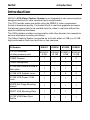
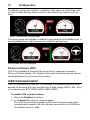
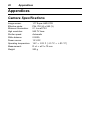
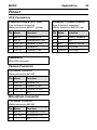
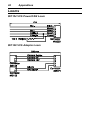
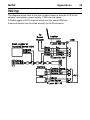
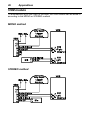
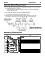
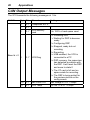
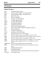
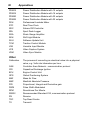
MoTeC
VCS User Manual
© Copyright – MoTeC Pty Ltd – 2010
The information in this document is subject to change without notice.
While every effort is taken to ensure correctness, no responsibility will be taken for the
consequences of any inaccuracies or omissions in this manual.
PN 63035 Rev 3.0, February 2010.
VCS User Manual
Contents
Introduction .............................................................................. 1 Features ............................................................................................. 2 Compatibility ............................................................................. 3 Accessories .............................................................................. 3 Installation ................................................................................ 4 Mounting ............................................................................................. 4 Wiring ................................................................................................. 4 CAN (Controller Area Network) Wiring...................................... 5 VCS Manager Software Installation .................................................... 5 Connecting the VCS to a PC .................................................... 6 i2 Pro Data Analysis Software .................................................. 6 VCS Manager............................................................................ 7 Owners ............................................................................................... 7 Configuration ........................................................................... 8 Configuration Templates ..................................................................... 8 Configuration Settings......................................................................... 9 Video Settings .......................................................................... 9 Audio Settings ........................................................................ 11 On Screen Displays Setup ...................................................... 11 CAN Communication .............................................................. 12 Save Configuration ................................................................. 14 Configure a MoTeC Data Logger ...................................................... 15 Configure a MoTeC 'hundred series' ECU ........................................ 16 Operation ................................................................................ 17 Sending and Retrieving Configuration Files ...................................... 17 Checking Operation .......................................................................... 17 Managing Videos .............................................................................. 18 Video Format .......................................................................... 18 Downloading Recorded Videos ............................................... 18 Video Browser ........................................................................ 19 MoTeC
VCS User Manual
Viewing Videos ....................................................................... 19 DVD Burner ............................................................................ 19 Renaming and Deleting Videos .............................................. 20 Firmware Versions and Updating ...................................................... 20 Matching Versions .................................................................. 20 Flash Card ........................................................................................ 21 Appendices ............................................................................ 22 Camera Specifications ...................................................................... 22 Pinout ............................................................................................... 23 Looms ............................................................................................... 24 Wiring ............................................................................................... 25 VSM module ........................................................................... 26 CAN Bus Wiring Requirements ............................................... 27 Mounting Dimensions ....................................................................... 27 CAN Output Messages ..................................................................... 28 Glossary ........................................................................................... 29 MoTeC
Introduction
1
Introduction
MoTeC’s VCS Video Capture System is an integrated in-car camera system,
designed and built for race cars and harsh environments.
The VCS records video and audio using the MPEG-2 video compression
format at broadcast quality. It includes a built in real-time graphics processor
that allows sensor data to be overlaid onto the video in real-time without the
need for additional hardware.
The CAN interface enables communication with other devices, for example to
set auto start/stop recording conditions.
The Video Capture System is supplied as a kit with either a 4 GB or a 16 GB
high performance flash card and one or two cameras.
Kit Number
VCS Pro Recorder
including memory card
#18201
#18204
#18205
#18206
#18201C #18204C #18201C #18204C
4 GB
16 GB
4 GB
16 GB
#18202 Camera
1
1
2
2
#18203 Microphone
1
1
1
1
#61149 Mini-USB B to USB A
Male cable
1
1
1
1
#61148 VCS Adapter Loom
1
1
2
2
#61154 VCS Power / CAN
Loom
1
1
1
1
#65076 Roll Cage Mounting
Bracket
1
1
1
1
#65077 VCS Mounting Plate
1
1
1
1
#61122 VSM Video Sync
Module
1
1
1
1
2
Introduction
Features
General
•
Solid state digital recorder.
•
Configurable two camera PIP – Picture In Picture system.
The second camera is optional.
•
Designed for motorsport applications.
•
Suitable for bikes, cars, marine and industrial applications.
•
Uses 12 V vehicle power - no recharging required.
•
Compact, durable and reliable unit.
•
CAN interface for easy connection to MoTeC Data Loggers and ECUs.
•
Video can be linked to logged data using MoTeC's i2 Pro data analysis
software.
•
In-car footage can be automatically synchronised to logged data using
MoTeC's VSM Video Sync Module (optional).
•
Programmable auto start/stop recording without driver interaction, using
any transmitted channel.
•
Gauges can be recorded live on the video.
•
Compact flash card, 4 GB or 16 GB.
•
Fast USB 2.0 download – no data cards to remove which eliminates bent
flash card pins.
•
Recordings are saved even after power loss.
•
Selectable video format.
•
Adjustable brightness, contrast, saturation and hue settings to ensure best
picture quality in all light conditions.
•
Adjustable microphone gain to ensure loud race engines do not overpower
the microphone input.
Display
•
Customisable screen layout.
•
Video player software with fast playback.
MoTeC
Introduction
3
Software
•
Windows-based software designed for video setup and management.
•
DVD burning software that is fast and simple to use.
•
The latest version can be downloaded from www.motec.com/downloads to
access the newest features.
Camera
•
High performance 1/3" colour CCP chip set.
•
Compact size, bullet style ø 21 x 71 mm.
•
Condensation free.
Compatibility
•
MoTeC 'hundred series' ECUs: M400, M600, M800 and M880.
•
MoTeC Data Loggers: SDL, ADL3 and ACL.
•
Check with your dealer for compatibility with earlier MoTeC ECU and Data
Logger models and other products.
Accessories
•
All parts of the kit are available separately for replacement or addition.
o #18202 Additional camera
o #18203 Additional microphone
o #61148 Additional VCS adaptor loom for second camera and
microphone
•
#68107 Replaceable lens cover
•
#61158 High performance flash card 4 GB
•
•
#61159 High performance flash card 16 GB
i2 Pro Data Analysis software – To analyse video in conjunction with the
logged data.
i2 Pro is available in two ways:
o Via the Pro Analysis upgrade on the ECU or Data Logger - refer to the
relevant device documentation for more information.
o Via the i2 Pro Feature Licence - refer to the online help in i2 Pro
software.
4
Installation
Installation
Mounting
The camera can be mounted using the roll cage mounting bracket included in
the VCS kit. Ensure the clamp is fitted in the middle of the camera.
It is not recommended to mount the camera using the rear screws as vibration
may cause damage to the camera.
When routing the wiring between the camera and the binder connector, only
lightly pull the cable ties. The wire can be damaged if cable ties are attached
too tightly. The routing should also avoid high heat sources.
Wiring
See Appendices for full connector, loom and wiring details.
MoTeC
Installation
5
The VCS recorder has four connectors:
•
A USB socket to connect to a laptop (D)
•
A power/CAN connector (C)
•
Two identical connectors (A and B) for two cameras and microphones.
The kit contains the following looms and cables:
•
A USB cable to connect a laptop (#61149)
•
An adapter loom to connect one camera and microphone (#61148)
• An unterminated loom for power/CAN (#61154).
Important: The VCS software must be installed before connecting the
VCS recorder to the laptop.
CAN (Controller Area Network) Wiring
The VCS connects to a CAN bus. This enables it to communicate with other
devices on the same bus and use data from a Data Logger (ADL3, SDL or
ACL) or a 'hundred series' ECU (M400, M600, M800, M880).
VCS Manager Software Installation
VCS Manager software is used for retrieving the audio and video data and for
configuration, testing and general management of the VCS.
Important: The VCS software must be installed before connecting the
VCS recorder to the laptop.
PC Requirements
VCS Manager is compatible with Windows XP or Vista operating systems.
The VCS connects to the PC via a USB port.
Installing VCS Manager Software
•
Go to the MoTeC website at www.motec.com, navigate to
software/latestreleases and select the software.
•
Save the selected file in your preferred location (for example desktop).
•
When downloading is finished, double click on the file and click Run.
•
Follow the instructions in the Install Shield Wizard.
•
To start the program after installation, click the icon on the desktop.
6
Installation
Updating VCS Manager Software
•
Software updates are available to give access to the latest features.
Follow the software installation instructions to download the latest software
version from the website and update to this version.
•
To update the associated firmware in the device, click VCS in the main
VCS Manager window. See Firmware Versions and Updating for more
details.
Connecting the VCS to a PC
The VCS connects to the USB port on the laptop with the mini-USB to USB
cable (USB 2.0 compatible).
The first time you connect the VCS to your laptop, the operating system will
detect the new hardware and launch the New Hardware Wizard. This will
automatically detect and install the driver.
If automatic detection fails, specify the location of the driver as C:\Program
Files\MoTeC\VCS Manager.
Once the driver installation is finished, the VCS hardware is ready to use.
i2 Pro Data Analysis Software
i2 Pro data analysis software can be used to analyse the video in conjunction
with the logged data recorded in the Data Logger or ECU. Any number and
combination of graphs, gauges and reports can be analysed simultaneously.
The i2 Pro environment can be customised to specific user requirements.
Note: Video footage can be manually aligned with logged data from both an
ECU or a Data Logger. Automatic video synchronisation is currently
supported for ADL3 and SDL Data loggers and requires the VSM (Video Sync
Module).
Contact your dealer for more information.
MoTeC
VCS Manager
7
VCS Manager
The main VCS Manager window contains the following buttons:
•
Import: This opens the Import window.
When a VCS recorder is connected, the VCS Manager software will detect
the presence of the VCS and automatically open the Import window.
•
Owners: This opens the VCS Serial Numbers window where the VCS
recorder and car details are entered.
•
Config: This opens the main Configuration window.
See the Configuration section in this manual.
•
VCS: This opens a window with a preview button to show the camera view
for setup and installation.
When software updates are available, they can be installed from here.
•
About: This shows information about the VCS Manager software. When a
VCS recorder is connected this will also show the current firmware version
in the device.
Owners
VCS Manager software can manage multiple VCS recorders. The details
entered in Owners are used in the automatic naming of imported videos. This
is very useful when downloading files from multiple recorders.
•
To add details for each VCS, click Owners and enter Serial Number, Car
number, Driver and Team.
•
To modify details, double click the required cell.
•
To delete a VCS from the list, right click the relevant row.
8
Configuration
Configuration
Many aspects of the VCS can be configured, for example when the recording
starts and stops, and which gauges will be included on screen. All settings are
stored in a configuration file on the laptop.
Changes to the configuration are performed offline, i.e. without the laptop
communicating with the VCS. The changes, saved in the configuration file,
must be sent to the VCS recorder before they take effect. See Sending and
Retrieving Configuration Files.
To make changes to the configuration file or to create a new configuration,
click Config to open the main configuration window. This allows you to
configure the following attributes of the VCS:
•
Video Settings
•
Audio Settings
•
On Screen Display Setup
•
CAN Interfaces
•
Start/Stop Recording Controls
Configuration Templates
A number of configuration templates are included in the software. These files
are configured according to frequently used settings. In most cases they can
be used directly, but if required, they can be changed to your preferences.
The following configuration templates are available:
•
Autostart – No gauges – No PIP
•
Autostart – Gauges – No PIP
•
Autostart – No Gauges – PIP
•
Autostart – Gauges – PIP
•
Speed or RPM start – No Gauges – No PIP
•
Speed or RPM start – Gauges – No PIP
•
Speed or RPM start – No Gauges – PIP
•
M800: Same settings as Speed or RPM start – Gauges – PIP, used when
connecting to a 'hundred series' ECU
•
Default: The factory settings are the same as Autostart – Gauges – PIP
The configuration templates include all CAN receiving messages.
MoTeC
Configuration
9
The Autostart configuration templates start recording when internal battery
voltage is detected. To stop recording, the VCS should be turned off.
The Speed or RPM start configuration templates start recording when engine
RPM > 1000 rpm or Speed > 10 km/h is detected. They will automatically stop
recording when engine RPM = 0 for 20 seconds.
There are templates available that include or exclude gauges and record with
or without PIP (Picture in Picture).
When using a 'hundred series' ECU for data logging, the M800 template
should be used. This template uses the five channels in the M800 dataset.
See Configure a MoTeC 'hundred series' ECU
To use a configuration template
1. In the main Configuration window, click Open.
2. Select the required template.
This will create a configuration file that must be sent to the VCS before
the changes take effect. See Sending and Retrieving Configuration
Files.
Configuration Settings
To make changes to the configuration file or to create a new configuration,
click Config to open the main configuration window.
Video Settings
Format
Choose 4:3 Letter or 16:9 Wide screen resolution.
Wide screen camera lenses are recommended for best 16:9 performance.
Quality
The VCS recorder has 3 Quality Settings; High (8 Mbits per second), Normal
(6.5 Mbits per second) and Low (4.5 Mbits per second)
Higher quality videos results in larger file sizes and longer download time.
Quality versus Approximate Recording Time
Card Capacity High Quality
Normal Quality
Low Quality
4 GB
1 hour
1 hour and 15 mins
1 hour and 45 mins
16 GB
4 hours
5 hours
7 hours and 15 mins
Note: For information purposes only, actual recording times may vary.
10
Configuration
Quality versus Approximate Download Time
Video
Length
Download time
High Quality
Normal Quality
Low Quality
30 min
2 min and 15 s
1 min and 45 s
1 min and 15 s
60 min
4 min and 15 s
3 min and 30 s
2 min and 30 s
90 min
6 min and 15 s
5 min and 15 s
3 min and 30 s
120 min
8 min and 30 s
6 min and 45 s
4 min and 45 s
Note: Indicative import times when connecting the VCS to a PC equipped
with a USB 2.0 compliant interface. Actual performance times may vary.
Video Image Controls
The following properties for the Video Digitisation can be modified:
Brightness
Brightness is the relative lightness or darkness of the colour, usually
measured as a percentage from 0 (black) to 255 (white).
The default value is 128.
Contrast
Contrast is the brightness ratio of the lightest to the darkest part of the
television screen image with values between 0 and 255.
The default value is 128.
Saturation
The saturation indicates the strength or purity of the colour (sometimes called
chroma). It represents the amount of grey in proportion to the hue, measured
as a percentage from 0 (grey) to 255 (fully saturated). On the standard colour
wheel, saturation increases from the centre to the edge.
Colours appear more "pure" with increased saturation and more "washed-out"
with decreased saturation.
The default value is 128.
Hue
Hue is the colour reflected from or transmitted through an object. It is
measured as a location on the standard colour wheel. Values are between 0
and 255, representing a degree between 0° and 360° on the colour wheel. In
common use, hue is identified by the name of the colour, such as red, orange,
or green.
The default value is 0.
MoTeC
Configuration
11
Audio Settings
Mono check box
Select the Mono check box to record both left and right audio channels from
the same (AV1) microphone input. This results in sound on both channels for
playback.
Clear the Mono check box to use two independent microphone inputs; AV1 for
the left channel and AV2 for the right audio channel.
Mic Gain
Mic gain can be used to improve audio quality. The volume of the recorded
audio can be reduced in noisy environments or increased in quiet
surroundings. The gain is applied to both microphone input channels.
On Screen Displays Setup
Gauges
The on-screen gauges can be positioned on the Top or the Bottom of the
screen.
Gauge Set
There are three gauge sets available, Small, Medium and Large.
The Small gauge set includes two gauges (default Speed and RPM), a red
and a green bar graph (default Brake and Throttle) and a centre numeric
display (default Gear).
Note: Brake bar not displayed
12
Configuration
The Medium gauge set includes, in addition to the elements of the Small set,
a G-force meter and two alpha numeric lines (default Lap number and Lap
time).
Note: Throttle bar not displayed
The Large gauge set includes, in addition to all elements of the Medium set, a
steering wheel and an alphanumeric line (default Last lap time).
Note: Brake bar not displayed
Picture in Picture (PIP)
The VCS is capable of recording the inputs from 2 cameras to provide a
Picture in Picture display. The location of the picture from the second camera
can be positioned in any corner of the screen.
CAN Communication
The VCS connects to a CAN bus. This enables it to communicate with other
devices on the same bus and use data from a Data Logger (ADL3, SDL, ACL)
or 'hundred series' ECU (M400, M600, M800, M880).
To enable CAN communications
1. Select the Enabled check box.
2. In the Speed list, click the required speed.
The VCS communication speed must be set to the same rate as the
communication speed of all other devices connected on the CAN bus.
The default value is 1 Mbit.
MoTeC
Configuration
13
Transmitting CAN Messages
You can use messages transmitted from the VCS to log or display VCS
information in a Data logger. Messages include camera status and card
usage.
To transmit CAN messages from the VCS
1. Select the Transmit Status check box
2. Select the Extended ID check box
3. In the Id box, type the CAN Id (in decimal) to suit your receiving device.
The default to suit any MoTeC Data Logger is 32.
The receiving device needs to be configured to receive the VCS messages.
When using a MoTeC Data Logger, this is all pre-configured if you select the
VCS receive template in the CAN communications setup.
See for more information Configure a MoTeC Data Logger.
Receiving CAN Messages
The Configuration templates provide for the standard set of received CAN
messages. If required, the templates are fully configurable to include different
sensors. Each sensor can be configured with respect to position, scaling,
name and attached gauge.
To configure a sensor
1. Double-click the row of the sensor to edit
- OR Double-click an empty row to add a new sensor.
2. Select the Enable check box to include the sensor in the received
messages.
3. Enter a Name. This is only used as a label.
4. In the Source list, click:
Internal for the VCS two internal sensors; battery voltage and internal
temperature,
- ORCAN for data from a MoTeC Data Logger or ECU.
5. Enter CAN message details:
Id: the address of the transmitted CAN message.
Offset: the location of the data from the start of the message.
Length: the size of the data.
6. In the Conversion and Resolution lists, select an appropriate value.
The conversion and resolution must be chosen to scale CAN data
down to the correct resolution for display.
14
Configuration
7. Enter GaugeId to determine on which gauge the channel will be
displayed.
Gauge Id List
1 Speed
2 RPM
4 Gear
5 Throttle
6 Lateral G-force
7 Longitudinal G-force
8 Lap Distance*
9 Brake Pressure
10 Limiter*
11 Steered Angle
12 Internal Voltage*
13 Lap Time
14 Lap Number
15 Last Lap
* currently not displayed
8. Enter the recording start and stop settings in the Event 1 and Event 2
conditions.
The recording can be started or stopped when the sensor value is
equal (=), greater (>) or smaller (<) than any entered value for a set
time.
Note: Ensure that there are no clashing start and stop conditions. For
example, the VCS will not record if the conditions to start and stop are
set at the same time.
To ensure all CAN messages are correctly received, the CAN receive settings
must match the settings from the transmitting device. When using a MoTeC
Data Logger or ECU for transmitting, the sections Configure a MoTeC Data
Logger and Configure a MoTeC 'hundred series' ECU will explain this further.
Save Configuration
When all settings are finalised, click Save As to save the configuration file.
The configuration file must be sent to the VCS recorder before the changes
take effect. See Sending and Retrieving Configuration Files.
MoTeC
Configuration
15
Configure a MoTeC Data Logger
The method described here is based on the ADL3 Dash Logger. Configuration
of other MoTeC Data Loggers will be very similar.
1. Open ADL3 Dash Manager and open a file.
2. On the Connections menu, click Communications.
3. Select an empty CAN slot and click Select.
4. Click VCS Receive.
This will make the following CAN messages, transmitted by the VCS,
available for the ADL3 to log or display:
• Memory Used
• Diagnostics
• Battery Voltage
• Internal Temperature
5. Select another empty CAN slot and click Select.
6. Click VCS Transmit Compound.
This will transmit all channels from the ADL3 to the VCS that are
included in the VCS configuration templates:
• Ground Speed
• Engine RPM
• Gear
• Throttle Position
• Brake Pressure Front
• Steered Angle
• G Force Longitude
• G Force Latitude
• Lap Distance
If any of these channels is not available in the ADL3, you can disable them in
the VCS configuration template. See Receiving CAN Messages.
16
Configuration
Configure a MoTeC 'hundred series' ECU
The method described here is based on Version 3 ECU Manager software.
Configuration in Version 2 ECU Manager software will be very similar.
1. Open MoTeC ECU Manager and open a file.
2. On the Adjust menu, click General Setup.
3. Click Communications and then click Setup Custom Data Sets.
4. Click the Custom Set 2 tab.
5. Click Add to add the following channels (in this order):
a. Ground Speed
b. Engine RPM
c. Gear
d. Throttle Position
e. Brake Pressure or G Force Longitude
Tip: Use G Force Longitude only if Brake Pressure is not
available in the ECU.
If any of these channels is not available in the ECU, you can disable
them in the VCS configuration template. See Receiving CAN
Messages.
6. Click OK.
7. On CAN Setup, select CAN 0 Data and enter 10 (Custom Data Set 2
Compound Tx).
Note: If CAN 0 is already in use, the VCS should be set up on CAN 1.
8. Select CAN 0 Address and enter 31.
9. Select CAN 0 Transfer Rate and enter 100.
MoTeC
Operation
17
Operation
For some operation activities, the VCS needs to be online, e.g. the laptop
needs to be connected to the VCS recorder.
When the VCS is communicating to the laptop, the VCS serial number will be
displayed in the main VCS Manager window. If the VCS has been entered in
the owners list, it will also display Car number and Driver.
Sending and Retrieving Configuration Files
1. Ensure the VCS is connected to the laptop using the mini-USB B to
USB A cable.
In the main VCS Manager window, click Config to open the
configuration window.
2. Click Send Config to send a configuration file from the laptop to the
VCS recorder,
– OR –
Click Get Config to retrieve a configuration file from the VCS recorder.
Checking Operation
The LED on the connector panel of the VCS recorder provides an indication
for the current mode.
VCS Mode
LED
Powered / ready to record
Slow flash (approx. 1 flash / 2 sec)
Recording
Steady flash (approx. 1 flash /sec)
Disk formatting
Fast flash (approx. 4 flashes /sec)
USB cable connected to PC
Off
Disk full
2 flashes and then a pause
Low power supply voltage
Flashes quickly
18
Operation
Managing Videos
Video Format
The Video Object file type (.VOB extension) is a container format in DVDVideo media. VOB is based on MPEG-2 program stream format, but has
additional limitations and specifications in the private streams. It contains the
actual video, audio, subtitle, and menu contents in stream form.
If the VOB file extension is changed to an MPEG-2 type file extension such as
.mpg or .mpeg, the file will still hold all information and is readable, but most
MPEG-2-capable players do not support subtitle tracks.
Tip: To play Video Object files In Windows, use a DirectShow compliant
media player or VLC media player.
Downloading Recorded Videos
Video Folder
All recorded videos will be downloaded in the current Video Folder. To change
the location of this folder, in the main VCS Manager window, click the Browse
button (
).
Note: videos recorded on your VCS can be quite large. Ensure that you have
a significant amount of free disk space.
To import a video from the VCS recorder to a laptop
•
Click on the video and then click Import.
While importing the Status column will show NEW (in red)
Tip: You can import multiple videos by selecting videos while holding
SHIFT (for a sequential video selection), or holding CTRL (for a nonsequential selection).
Note: The import process can take some time depending on the speed
of your computer. The import process has completed when the Status
column shows Imported (in green).
To prepare the VCS for new recordings
• Click CLEAR Card.
Warning: This will erase all of the videos from the VCS recorder. If you
have not imported the videos prior to clearing the card, they will be lost.
MoTeC
Operation
19
Video Browser
Via the Video browser in the main VCS Manager window, all imported videos
can be accessed. The Video browser displays file name, date, time, duration
and size.
The file name is automatically generated on import. The structure of the file
name is CarNumber_DayMonthYear_RecordStartTime.VOB
Viewing Videos
To watch a video
• Double-click the video in the browser to open the selected video in
Windows default media player assigned to VOB Files.
MoTeC recommends Video Lan VLC Media Player.
Note: VLC Media Player is not a MoTeC product. The player can be
downloaded from the internet and should be installed on the laptop.
—OR—
• Right-click on the video and select Play to open the file in VCS Player.
Note: The VCS Player does not support Audio Playback.
DVD Burner
To play the videos on a standard DVD player or to free up space on your
laptop, VCS Manager can burn the videos to a DVD.
Note: Only DVD-R disks are supported.
To burn videos to DVD
1. Select the videos you wish to record. You can select multiple videos,
but ensure the maximum total combined size is less than 4 GB.
Tip: hold the CTRL key while selecting to add videos to the selection.
2. Right-click one of the selected videos.
3. Click Add to Burn List for later burning to DVD,
—OR—
Click Burn DVD to open the DVD Burner application.
The main section of the window will list all the videos you have selected
to burn to the DVD.
4. From the Drive box select the drive where the DVD burner is located.
5. Enter a Disk Name.
The default is MVS followed by today's date.
20
Operation
6. Insert a blank disk into the selected DVD Drive and click Burn.
This option is only available when a blank disk has been inserted.
When the DVD is being recorded the progress bar will be displayed.
Renaming and Deleting Videos
To rename the video
• Right-click on the file and click Rename.
Note: You cannot change the file extension from .VOB
To delete a video
• Right-click on the file and click Delete.
Note: This removes the file from your computer and cannot be undone.
Firmware Versions and Updating
The software inside the VCS recorder (firmware) can be updated by the user
at any time to take advantage of the latest features.
VCS firmware consists of two files: DSP Firmware and Supervisor Firmware.
To update the firmware
1. Ensure the VCS is connected to the laptop.
In the main VCS Manager window, click VCS.
2. Select the Browse button (
) next to the type of firmware you are
updating.
3. Browse to the file you wish to update and then click Update.
4. To activate the upgrade, unplug the USB cable from the VCS recorder.
The status LED will flash quickly while the upgrade is in progress. This
can take up to one minute. The VCS will then return to a ready state.
MoTeC recommends to power cycle the VCS (turn off and on) after a
firmware update.
Warning: Do not power down the VCS while the upgrade is in progress
(LED still flashing).
Matching Versions
The firmware version in the recorder must match the version of VCS Manager
software on the laptop in order to communicate.
MoTeC
Operation
21
Tip:
To check the versions, in the main VCS Manager window, click About.
This will display the laptop's VCS Manager software version and the version
of both firmware files.
Flash Card
The internal flash card used by the MoTeC VCS has special safeguards to
protect data from loss in the event of a sudden power loss. The format of the
flash card is a proprietary format by MoTeC.
Occasionally it might be required to reformat the flash card.
To format your flash card
CAUTION: This will cause all data on the VCS to be lost, including
configurations and all recordings.
1. Ensure the VCS is connected to the laptop.
In the main VCS Manager window, click VCS
2. Click Format (upper left section of window)
3. Click OK to confirm format request.
22
Appendices
Appendices
Camera Specifications
Image sensor:
Effective pixels:
Minimum illumination:
High resolution:
Shutter speed:
White balance:
Power source:
1/3" Super HAD CCD
PAL 752 (H) x 582 (V)
0.1 Lux at F2.0
560 TV lines
Automatic
0.005%
12 V DC
Operating temperature:
Measurement:
Weight:
14 F ~ 122 F (-10 °C ~ +50 °C)
D x L = ø21 x 72 mm
200 g
MoTeC
Appendices
Pinout
VCS Connectors
Connector A and B (AV1, AV2)
5 pin Autosport connector
Mating connector #65071 (yellow)
Connector C (Power/Comms)
5 pin Autosport connector
Mating connector #65033 (red)
Pin Name
Function
Pin Name
Function
Battery Negative
1
Mic In
Microphone In
1
Bat–
2
3
4
5
Mic 0V
Cam 12V
Cam In
Cam 0V
Microphone 0 Volt
Camera 12 Volt
Camera In
Camera 0 Volt
2
3
4
5
N/C
Bat+
Battery Positive
CAN LO CAN Low
CAN HI CAN High
Connector D
Mini-USB connector
Camera Connector
4 pin Binder Connector
Mating connector #68105
Pin Name
Function
1
2
3
4
Camera Out
Camera 0 Volt
Camera 12 Volt
N/C
Cam Out
Cam 0V
Cam 12V
Microphone Connector
3 pin Binder Connector
Mating connector #68106
Pin Name
Function
1
2
3
Microphone 0 Volt
Microphone Out
N/C
Mic 0V
Mic Out
23
24
Appendices
Looms
#61154 VCS Power/CAN Loom
#61148 VCS Adapter Loom
MoTeC
Appendices
Wiring
The diagram shows how to use the included looms to wire the VCS to the
camera, microphone, power supply, CAN bus and laptop.
A Dash Logger or ECU must be wired onto the same CAN bus.
A second camera can be wired similarly to the B-connector
25
26
Appendices
VSM module
To automatically sync the video to the data, the VSM module can be wired in
according to the MONO or STEREO method
MONO method
STEREO method
MoTeC
Appendices
27
CAN Bus Wiring Requirements
•
The CAN bus should consist of a twisted pair trunk with 100R (0.25 watt)
terminating resistors at each end.
o If the CAN bus is less than 2 metre (7 ft) long, a single termination
resistor may be used.
•
The preferred cable for the trunk is 100R data cable.
•
The maximum length of the bus is 16 metre (50 ft)
•
CAN devices (such as MoTeC Data Loggers, ECUs etc.) may be
connected to the trunk with up to 500 mm (20 in) of twisted wire.
Mounting Dimensions
28
Appendices
CAN Output Messages
The VCS transmits the following messages at 1 Hz.
CAN ID
Byte Bit
Channel
0
1
0..7
0..7
Compound Id = 0
2
0..7
VCS Memory
used
Base Id + 0
3
0..7
VCS Diag
4,5
6,7
0..7
0..7
Batt Volts VCS
VCS Temp
Scaling
0 to 100% of card space used
0 = Initialising DSP
1 = Waiting for DSP to become
ready
2 = Configuring DSP
3 = Stopped, ready but not
recording
4 = Recording
5 = USB enabled, the VCS is
connected to a PC
6 = DSP recovery, the supervisor
has detected a problem with
the DSP. It will reset the DSP
and move to state 0
7 = The CF card is full and no
space exists for recording
8 = The DSP is being polled for
the preview picture on the
config screen
Batt voltage in 0.01 V steps
0 to 128 °C in 0.1 °C steps
MoTeC
Appendices
29
Glossary
MoTeC Devices
ACL
ADL2
ADL3
BR2
BTX
CIM
CLS
DBW4
E816
E888
i2
i2 Pro
IEX
LTC
LTCD
M2R
M4
M400
M48
M600
M800
Advanced Central Logger
Advanced Dash Logger - second generation
Advanced Dash Logger - third generation
Beacon Receiver
Beacon Transmitter
Computer Interface Module
Central Logging System
Drive By Wire expander
Input/Output Expander
Input/Output Expander
MoTeC data analysis software
MoTeC data analysis software, professional version
Ignition EXpander
Lambda to CAN module
Lambda to CAN Dual module
ECU dedicated to run 2 rotor engines
ECU for engines with up to 4 cylinders or up to 2 rotors
ECU for modern engines with up to 4 cylinders or up to 2 rotors
ECU for engines with up to 8 cylinders and 2 rotors
ECU for modern engines with up to 6 cylinders or up to 3 rotors
ECU for modern engines with up to 12 cylinders or up to 4
rotors
M800 Plug-In ECU for direct replacement of a factory ECU
M880
ECU for modern engines with up to 12 cylinders or up to 4
rotors
MDC
Mitsubishi Diff Controller
MDD
Mini Digital Display
MLS
ECU dedicated to run Chevrolet LS1 and Lexus/Toyota V8s
PCI cable
PC Interface cable
30
Appendices
PDM15
PDM16
PDM30
PDM32
PLM
RTC
SDC
SDL
SGA
SLM
SUU
TCM
VIM
VCS
VSM
Power Distribution Module with 15 outputs
Power Distribution Module with 16 outputs
Power Distribution Module with 30 outputs
Power Distribution Module with 32 outputs
Professional Lambda Meter
Real Time Clock
Subaru Diff Controller
Sport Dash Logger
Strain Gauge Amplifier
Shift Light Module
Software Update Unit
Traction Control Module
Versatile Input Module
Video Capture System
Video Sync Module
Other
Calibration
CAN
CDI
ECU
GPS
MAF
MAP
PID
PWM
RPM
RS232
RX
TDC
TX
The process of converting an electrical value into a physical
value, e.g. Volts into kilometres per hour
Controller Area Network - communication protocol
Capacitive Discharge Ignition
Engine Control Unit
Global Positioning System
Mass Air Flow
Manifold Absolute Pressure
Proportional, Integral and Derivative gain
Pulse Width Modulated
Revolutions Per Minute
Recommended Standard 232, communication protocol
Receive
Top Dead Centre
Transmit
MoTeC
Notes
31
32
Notes