1
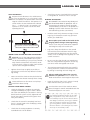
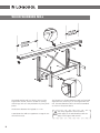
USER MANUAL TRANSLATION OF ORIGINAL USER MANUAL. Customer no: M8 serial number: LOGOSOL M8 Read through the user manual carefully and make sure you understand its contents before you use the machine. This user manual contains important safety instructions. WARnIng! Incorrect use can result in serious or fatal injuries to the operator or others. Thanks for choosing a logosol sawmill! you have demonWelcome! We are very pleased that ng this sawmill hasi strated your confidence in us by purc r t you expectations. and we will do our utmost to mee sawmills since 1988, Logosol has been manufacturing roximately 30,000 and in that time we have supplied app world over. machines to satisfied customers the ty and ensuring that We are concerned with your safe with your bandsaw you achieve the best possible results take the time to you that end mill. We therefore recomm ual and the man user ry carefully read this supplementa peace and in r cove to r standard user manual, from cove er that emb Rem . saw quiet before you begin using the uct. prod the of e valu the machine itself is just part of the e ertis exp the in d Much of the value is also to be foun a be ld wou It . uals we pass on to you in the user man pity if that were not utilised. ion from the use of We hope you get a lot of satisfact your new machine. Bengt-Olov Byström Founder and chairman, Logosol in Härnösand, Sweden LOGOSOL continuously develops its products. For this reason, we must reserve the right to modify the configuration and design of our products. Document: Logosol M8, user manual Manual, part no.: 4508-001-1004 Text: Mattias Byström Pictures: Mattias Byström, Lars Wahlström Last revised: December 2011 © 2011 LOGOSOL, Härnösand, Sweden 2 LOGOSOL M8 Table of contents Safety instructions 4 Description of machine 6 Technical data, required tools 7 Woodworkers Mill 8 Logosol sawmill components 9 Assembly: leg units 10 Assembly: sawmill beam 11 Assembly: adjustment beam and cross beam 12 Assembly: beam strut 13 Assembly: log support and log bed 14 Assembly: saddle plate & latch 15 Assembly: crank and lifting line 16 Assembly: log holder 16 Assembly: saw carriage 17 Assembly: tip guard 18 Assembly: Logosol nuts 18 Assembly: chainsaw 19 Assembly: log ladder, log support 20 Siting 21 Adjustment 22 Sawing 25 Troubleshooting 28 Cutting equipment 31 Fine tuning the M8 33 Accessories 36 Parts list 37 3 safety instructions • Read carefully through the entire manual before starting to operate the Logosol sawmill. Failure to observe these safety instructions may result in fatal injuries. • Make sure that everyone who uses the Logosol sawmill is well informed of the dangers and has read the manual. The manual must also be available to everyone who uses the sawmill. This is also applies where the sawmill is sold or loaned out. • Read the manual and safety rules for the sawing unit used on the Logosol sawmill. • Minors under 18 years of age should not be allowed to operate the Logosol sawmill. • Make sure that children and animals are not in the vicinity when the sawmill is being operated. • The Logosol sawmill is a one-person machine. Respect the safety distances to avoid injury from high noise levels and from chain thrown-off in the direction of the guide bar if the chain breaks. • • • • 4 Anyone working with the Logosol sawmill must be fit for work, healthy and in good physical condition. Make sure you take regular breaks when operating the machine. Never operate the machine while under the influence of alcohol, narcotics or other drugs or medicines that can cause drowsiness or in-attention. The Logosol sawmill is only to be operated where visibility is good. It is not to be operated in the dark or where visibility is poor. Never work alone and make sure there are other persons within earshot who you can summon if you need help. Only add extra equipment to the sawmill that is made by Logosol or that is specifically approved by Logosol for the purpose. Other equipment can cause accidents and should not be used. Logosol will not accept liability for personal injury or material damage incurred while using non-approved attachments on the sawmill. • Support legs must be fitted under the guide rail ends where the sawing unit weighs more than 15 kg. Risk of overturning! • Always wear protective clothing and use personal protective equipment: Close-fitting work overalls are appropriate. Never operate the unit wearing loose-fitting clothes, overall coats or similar. • Use safety shoes with high-grip soles and steel toecaps. Neckerchiefs, ties, jewellery or other items that can get caught in the equipment are not to be worn. • Never stretch over or under the Logosol sawmill's guide rail when the sawmill is in operation. Rotating cutting equipment. Risk of cut injuries! • Wear strong protective gloves. Risk of cut injuries when handling the guide bar and the saw chain. Cutting equipment can also be hot immediately after sawing. Remember that hearing can be damaged after relatively short periods of exposure to the high frequency noise of the motor and the cutting equipment. Key to symbols For your own safety, read through the entire user manual carefully and do not start the machine before you have understood everything. Use approved ear protectors and protective eyewear. Hearing can be damaged even after short periods of exposure Sharp rotating tools. Make sure that your fingers never are in or move into the vicinity of the cutter. This symbol means 'WARNING'. Pay particular attention where this symbol appears in the manual text. A warning comes after this symbol. Pay particular attention where this symbol appears in the manual text. LOGOSOL M8 SAFE DISTANCES Respect the safe distances. The safe distance is 8 m for the operator or 15 m for persons other than the operator. The picture below shows the Logosol sawmill from above. The operator is to remain within the area marked with a dashed line (- - - -) when the saw is in operation. The operator is not to stretch over the line when operating the unit. • During operation: The sawmill is not to be in any other position than level when in operation. Risk of overturning! The Logosol sawmill should be fastened directly to the floor or be placed on a bedding of planks which increases the area of the load bearing surface (see manual). • • Logs must always be rolled on to the sawmill level with the horizontal beam. Never lift logs from ground level directly up onto the sawmill. There is a risk of damage if the log drops or if the sawmill overturns! • Do not saw short logs that do not extend more than 0.2 m beyond each log bed. A shorter log can fall off when the log beds are raised! • The maximum permitted load for the sawmill is 500 kg. Extensions increase the maximum load by 250 kg for each leg unit with lifting unit. When using petrol driven chainsaws: • • Tighten the tank cap as tightly as possible, to minimise the risk that the cap vibrates loose during sawing. Before each work period: • Always stand to the right of the saw unit when it is in operation. Chains or bands that break can be thrown out through the chip outlet. Never saw with the chainsaw throttle locked. Always operate the throttle manually when sawing. Increased throw-out risk! Never use rip sharpened chain when cutting. Check the lifting line's condition in particular. Change immediately any sign of wear is detected. Check that bolted joints and locks in the log bed lift and lock system are fully tightened and that all the Logosol sawmill moving parts move freely and smoothly. • Check that the sawmill is completely level and that it is securely fixed to the underlying surface. Risk of overturning! • Check that the cutting equipment is correctly assembled. Risk of chain breaks! Hold the crank firmly whenever raising or lowering a log. If released, the crank may spin back and hit your hand hard. Do not place your hand on the inside of the long leg when raising or lowering the log. There is a risk that your hand can be trapped if the lifting line snaps or the crank spins. The operator's position during operation. Fire risk. Turn off the engine before refuelling. Petrol is extremely inflammable. Burn injuries can be life threatening. If you spill fuel, immediately clean the components the fuel has come in contact with. Clothes on which fuel has been spilt are to be changed immediately. Check that saw unit is pushed fully into position on the guide rail. Throw-out risk on start up! • Keep the worksite free of tools, pieces of wood, chips and other items you can trip on. Turn the chain-saw off after each cut. Never leave the Logosol sawmill unattended such that unauthorized persons can start it. Stop sawing immediately and turn off the chainsaw, if any problem occurs, until it has been resolved. Always keep this in mind. Most accidents with dangerous machines, both Logosol sawmills and other machines, happen when something goes wrong and the operator attempts to fix it while the machine is still running. A stop seldom shows up on the finished product. 5 DESCRIPTION OF MACHINE • • • • • • • • • Log ramps which make the loading of logs easier, are standard equipment. These make operation easier, particularly where the M8 is temporarily set-up. All aluminium components are anodized and completely rustproof. The outer surface is as wear resistant as tempered steel, has a low friction coefficient and is easy to keep free of resin and chips. Adjustable feet make it easy to compensate for uneven surfaces. M8 has double latches. Simple shift by hand between 1/4” (6.25 mm) and 1/8” (3.12 mm). Clear scales show the height of the log bed. Extra measuring rods are available as accessories to show sawing height settings. The cross beam between the short legs stabilizes the sawmill significantly. The crank axle runs through maintenance-free bronze bearings that do not wear out. The slide rails use low-friction plastic that has a long lifetime thanks to the superbly smooth surface anodization. The settings for sawing parallel to the grain of conical logs are quick and simple to set.(The log beds can be set at different heights so that more than half of the cuts give acceptable yields.) Many accessories for the M5 and M7 also can be used with the M8. Maintenance The Logosol sawmill should be kept clean, and all plastic parts should be lubricated with Logosol’s lubricant (7500-001-5050) or silicone lubricant (7500001-5067). Regularly check the condition of the lifting lines. Tempered parts: The ratchet cam, the ratchet cam axle and the ratchet bar are only lightly protected against rust and should be kept coated with a thin layer of Superflo (999-000-5115) to prevent rust. Service The sawmill must be inspected regularly and maintained as needed. Only carry out the maintenance and repairs specified in the manual. Other repairs must be carried out by Logosol or by authorized Logosol dealers. 6 Do not make any alterations to the construction of the sawmill as this can increase the risk of accidents. After service, the Logosol sawmill should be in its original condition. Logosol accepts no liability for damage that occurs while working on an improperly modified machine. Partially assembled M8 unit The Logosol M8 sawmill, partially assembled version. Only the beam and and the strut need to be fitted, refer to page 11-13. The partially assembled M8 unit will still need the same siting and adjustments as are described in this manual. (Page 21 ff) Assembly The Logosol M8 sawmill is designed for simple assembly and adjustment. The unit therefore has fewer parts and fewer settings than previous models of the Logosol sawmill. Set up on an underlying surface which does not scratch the surface treatment during assembly. Save time by reading through the entire assembly instruction before assembly is begun and then follow the instructions step by step. When this symbol appears, tighten the fasteners so that they still can move. When there is no symbol, tighten the bolts well. LOGOSOL M8 required tools (Tools are not supplied with the sawmill.) • • • • • • • Ring or flexible head spanner 10 mm Ring or flexible head spanner 13 mm Ring or flexible head spanner 17 mm Ring or flexible head spanner 16 mm Allen key 4 mm Allen key 8 mm Set square 2 pieces 1 piece 1 piece 1 piece 1 piece 1 piece 1 piece A battery-driven drill or screwdriver with a 10 mm hexagon socket and a ratchet key with 10 and 13 mm hexagon sockets will make assembly easier. technical data Length: Width: Width of log bed: Weight: Weight with carriage for chainsaw: Max. rec. log diam.: Max. rec. log length , standard version: Max. log weight: 5.5m. 1.25m 0.5m 52 kg 57 kg 0.6m 5m 500 kg 7 WOOD WORKERS MILL The Wood Workers Mill is a shorter version of the Logosol M8 sawmill, which is suitable for sawing shorter logs such as in the production of joinery workpieces. The leg units on the Wood Workers Mill are fitted and adjusted in the same way as on the Logosol M8 sawmill. The Wood Workers Mill is otherwise assembled as shown in the picture above. The distance between the log beds is 1.13m. A Wood Workers Mill can supplement a Logosol sawmill and vice versa. 8 The safety regulations and instructions which apply to the Wood Workers Mill also apply to the Logosol M8 sawmill. LOGOSOL M8 LOGOSOL SAWMILL COMPONENTS Below is a brief description of the Logosol sawmill components to assist in identifying them during ass embly. A more complete parts list is found at the end of the manual. 13 Left 24 Operator side 10 1 Right 12 2 21 6 7 4 5 8 1 2 3 4 5 6 7 8 9 10 11 12 13 14 15 16 17 18 19 20 21 22 23 24 Guide rail Joint coupler Long leg Horizontal beam Short leg Cross beam Adjustment strut Log bed Log holder with log clamp Beam strut Foot Log support Knee connector Carriage Line attachment Lifting beam Ratchet bar Ratchet bar stop plate Saddle plate Ratchet cam Ratchet cam axle Scale selector Scale selector plate Turn spring Crank Lockring Lockring with line attachment Plastic slide rail on log bed Indicator Log ladder Line pulley Log support 9 14 22 15 20 3 17 18 19 16 23 9 ASSEMBLY: LEG UNIT A 1 2 3 4 Part number 4508-001-1200 4508-001-1035 4508-001-1030 4508-001-1045 4508-001-1040 Description Horizontal beam Short leg Long leg Knee connector Foot The right and left leg units are assembled in the same way. The bolts listed below are for one leg unit. (1) Fit the horizontal beam to the short leg. Be careful not to damage the bevelled faces before assembly. (4 x M6x20 bolts, 4 x M6 collar nuts) (2) Fit the horizontal beam to the long leg. The scale plate is fitted to the long leg using the two lower bolts. 10 4 Tighten all four bolts loosely to allow the two beams to move in relation to each other. (4 x M6x20 collar bolts, 4 x M6 collar nuts) (3) Fit the angle fitting to the long leg and to the underside of the horizontal beam. First, tighten the four bolts on the angle fitting loosely, then gradually tighten all the four bolts until they are firmly tightened. This ensures that the leg unit is set at exactly 90°. Check using a set square. (4 x M6x20 collar bolts, collar, 4 x M6 collar nuts). Finally tighten the bolts between the horisontal beam and the long leg (2). (4) Fit the sawmill feet. Turn the foot so that the securing hole in the underlying surface is aligned with the leg beam opening. The foot's and the leg's grooves form a cross. Make sure that the foot runs straight in the leg. (4 x M8x25 allen head bolts, 4 x M8 collar nuts, 4 x M8 washers) (A) Assemble the pulley, see picture. (1x M6 collar nut) LOGOSOL M8 ASSEMBLY: SAWMILL BEAM 5 6 7 9 8 Part number 4508-001-1000 4510-720-6700 4510-723-0800 Description Guide rail 2.75 m Joint coupler 300 mm Joint plates The position of the holes in the beam part ends differ and must be turned correctly. Work on a level surface. Cut the beam cardboard in half and place the two halves after each other to form an underlay to ensure that the slide rails are not scratched. (5) Make sure that the bolts in the joint coupler are loose. They should be loosened approximately one turn from the point at which they begin to tighten. (4 x M8x35 allen head bolts, 4 x M8 square nuts) (6) Insert the joint coupler in one end of the beam so that the allen head bolts are accessible through the two holes in the side of the guide rail. Tighten the innermost bolt somewhat. The joint coupler must be turned in the correct direction. See fig. The joint opening must be turned towards the beam sliding surface. Coat the sides of the joint coupler with oil. This is important, to ensure that the joint expands in the right way when the bolts are tightened. (7) Fit the other beam over the joint coupler and push the sections completely together. If the beam cannot be easily pushed onto the joint coupler, this can be because the beam parts are not correctly aligned or that the innermost bolt is too tight. (8) Tighten the four allen head bolts. (9) Fit the joint plates. (4 x M6x20 collar bolts, 4 x M6 collar nuts) 11 ASSEMBLY: ADJUSTMENT BEAM AND CROSS BEAM B A 10 11 For extending the sawmill: C D Part number Description 4508-001-1010 Adjustment strut 4508-001-1009 Cross beam (10) Fit the adjustment strut. Use a short bolt on the side where the strut is bolted to the back of long leg (A), to pull the strut right up against the leg. (1 x M10x40 bolt, 1 x M10 washer) On the side where the strut enters the leg profile (B), use a long bolt with a nut on the inside of the leg. Screw the bolt approximately 20 mm into the adjustment strut. Do not tighten this bolt. (1 x M10x50 bolt, 1 x M10 nut, 1 x M10 washer) 12 (11) Fit the cross beam. There are six holes in each leg unit. The innermost holes are used for the standard M7 (C). (6 x M6x20 collar bolts, 6 x M6 square nuts) (D) The other three holes are used when the sawmill is extended and an additional cross beam is fitted on either side (accessory). Or when a 0.5 m central extension is used. Then 3 bars (4507-0011221) with two threaded holes are fitted instead of the 6 square nuts. LOGOSOL M8 ASSEMBLY: BEAM STRUT 12 13 A B 13 13 Part number 4508-001-1015 4508-001-2073 4507-001-1178 Description Beam strut Screw bag no.73 End plug (12) Place the beam on the long leg. Press the guide rail downwards against the long leg and tighten the bolts at the same time. (4 x M6x20 collar bolts, 4 x M6 collar nuts) Press the plastic end plugs into the beam ends. Check that the angle between the beam and the long leg is 90° in both directions. (13) Fit the strut to the inside (A) of the beam's flanges with the oval hole facing upwards. (10 x M6x20 collar bolts, 10 x M6 collar nuts) Fit the end plug to beam (B). Two struts are fastened to the same hole on the the long leg (the side facing the operator). Do not tighten the strut bolts hard. Refer to adjustment, page 22. 13 ASSEMBLY: log support & log bed (14) Fit the log support. (2 x M6x20 bolts, 2 x M6 collar nuts) 14 (15) Feed the plastic slide into the log bed track. Fit the longer scale (A) to the plastic slide on the left log bed and the shorter scale (B) to the right log bed side. Do not tighten the bolts hard. (2 x M6x30 allen head bolts, 2 x M6 collar nuts) (16) Fit the ratchet bar holder under the lifting beam. (2 x M6x25 allen head bolts) (17) Fit the line pulleys. The bolt is stiff, so press it inwards hard until it begins to move. (1 x M6x60 bolt) Part number Description 4508-001-1075 Log support 4508-200-0010 Scale 15 A C 18 B 15 19 17 Part number 4507-001-1190 4507-001-1165 4507-001-1170 4507-001-1150 4507-001-1145 4510-723-3900 4508-001-1050 4508-001-1065 14 Description 16 Setting block for log bed Short indicator D Long indicator Ratchet bar Ratchet bar holder Line pulley Log bed Lifting beam (18) Fit the log bed to the lifting beam. The bolts will be stiff to screw through the holes. Therefore use an Allen key to pull the log bed down to the lifting beam. These bolts will need to be retightened after approx. 20 hours of use. (C) Fit the bolt for additional support to the bed's bottom position. (4 x self-threading M8x30 allen head bolts, 1 x M8x16 allen head bolt, 5 x M8 collar nuts) (19) Fit the ratchet bar. Thread the adjustment bolt (D) through the ratchet bar holder and screw on the nut. Do not tighten. Place the ratchet bar in the track of the lifting beam and tighten the adjustment nut on the ratchet bar until the ratchet bar is approx. 5 mm under the upper edge of the lifting beam. (1 x M10x40 bolt, 1 x M10 nut) LOGOSOL M8 ASSEMBLY: SADDLE PLATE & RATCHET CAM (20) Thread the lifting line through the hole on the lower edge of the saddle plate and make the knot shown (A). A There should be 1 cm of line left after the knot. (21) Press the steel sleeves into the holes in the plastic glides. Place the plastic glides (B) on each side of the lifting beam and fit the saddle plate over these. (4 x M6x40 collar bolts, 4 x M6 collar nuts) 21 B 20 Part number 4507-001-1080 4507-001-1090 4508-001-1085 4507-001-1095 Description Lifting line, 2.05 m Plastic glide, saddle plate Saddle Plate, compl. Spacer sleeve 22 23 (23) Thread the spring's short wire through the ratchet's spring attachment and thread it onto the rod inside the long leg. Feed the shaft further through the saddle plate's first flange. Thread the ratchet cam in front of the opening into the saddle plate. An o-ring should be fitted on each side. Turn the shaft so that the ratchet cam locking screw is immediately in front of the milled groove in the shaft. Draw the locking screw down into the milled groove. (1 x M6x10 bolt) Draw the ratchet's locking screw down into the other milled groove. (1 x M6x10 bolt) B Part number 4507-001-1110 4507-001-1120 4507-001-1115 (22) The ends of the ratchet cam axle are different. Feed the side with the milled groove closest to the end, in through the first lower hole in the long leg. Description Ratchet cam axle Turn spring Scale selector Use protective gloves when carrying out the following: (B) Tighten around the spring's long wire and hook it so that it is securely fixed to ratchet plate's spring attachment. Part number Description 4507-001-1125 Ratchet Cam 15 ASSEMBLY: crank & lifting line (24) Thread the lifting line under the lifting beam's outer pulley, straight up and around the pulley in the horisontal beam (A) and then down under the inner line pulley in the lifting beam. A Thread the shaft through the upper hole in the long leg and through the middle flange bushing. 24 Place the lifting line in the locking ring's milled groove. Thread the bushing and line on and the other bushing on the crank rod. Push the crank rod through so that it ends around 2 mm beyond the saddle plate's outer bushing. Part number Description 4507-001-1100 Crank rod 4507-001-1105 Stop ring, track Part number Description 4507-001-1106 Stop ring 4507-001-1125 Ratchet Cam Draw the bushings' locking screws down into the crank rod's milled groove. Tighten the allen head bolts which lock the line on the opposite side. (3 x M6x6 allen head bolts) ASSEMBLY: log holder Part number Description 4507-001-1101 Crank handle 4508-001-1025 Log holder, log clamp 25 A 16 (25) Slide the log support and log clamp onto the log bed. (A) Attach the crank handle by inserting a 4 mm Allen key into the handle bolt to hold the bolt while tightening the nut. (1 x M8 locking nut) LOGOSOL M8 ASSEMBLY: CHAINSAW CARRIAGE Part number 9999-000-1032 4510-720-2800 4508-720-7402 4508-001-2901 4508-001-2900 4510-723-2002 4510-723-2904 Description Line spool Spool holder Sliding block, aluminium Chainsaw bed Pylon Chainsaw feed line Plastic carriage slide 27 29 26 28 (26) Insert bolts through the holes along the sides of the chainsaw bed and the spool holder. Turn the square nuts a few times. (8 x M6x16 bolts, 8 x M6 square nuts) (28) Feed the square nuts into the plastic slide track. Slide the the spool holder and the chainsaw plate to each end of the slides and tighten the bolts. (27) Fit the fixed pylon to the the chain guard on the carriage plate (4 X M6x16 bolts, 4 x M6 washers, 4 x M6 locking nuts.) (29) Thread the line spool onto the spool holder arm and screw on the nut (1 x M10 locking nut). 17 ASSEMBLY: CHAIN GUARD (30) Fit the chain guard on the support and bolt. (2 x M6x40 collar bolts, 2 x M6 collar nuts) 30 Part number Description 4508-723-4809 Chain guard 4508-720-3001 Chain guard mount ASSEMBLY: LOGOSOL NUTS Remove the two bolts holding the guide bar and remove the guide bar cover. (31) Remove the bark grips, but leave the bolts in place and retighten the nuts. 31 32 Part number Description 4510-723-3402 Logosol nut 066 18 (32) Refit the guide bar cover, replacing the guide bar bolts with Logosol nuts. (The guide bar nuts will later be used to fit the chainsaw to the carriage.) Only CE-approved chainsaws with two guide bar nuts may be used with the Logosol sawmill. LOGOSOL M8 ASSEMBLY: CHAINSAW & GUARD MOUNT 34 Min 55 cm 33 (33) Fit the Logosol nuts through the chainsaw plate track using the front hole. (For some chainsaw models, the rear hole has to be used to ensure that the saw cover will not extend too far out. However, this is relatively unusual.) Tighten the chainsaw into place using the chainsaw's guide bar nuts under the plate. (34) Fit the chain guard support to the guide bar plate so that the guard sits app.4 cm from the tip of the guide bar. (2 x M6x40 collar bolts, 2 x M6 collar nuts) 35 Check that the carriage runs smoothly and easily on the beam. If not: Slide the carriage onto the beam, loosen the eight screws which hold the slides in place, rock the carriage a little and then tighten the eight screws again. If this is not sufficient, check that the plastic glides on the carriage are not damaged. (35) Push the carriage onto the guide rail with the guide bar in the direction of the log beds. 19 ASSEMBLY: Log ladder, log support & line attachment (36) Assemble the two log ladders' sides plates. 37 (37) Fit the spacer sleeves between the side plates. (16 x M8 45, 32 x M8 washers, 16 x M8 loose nuts) (38) Place the foot angle pieces on the outside of the side plates. (2 x M8 x 50, 16 x M8 45, 18 x M8 washers, 18 x M8 loose nuts) 36 (39) Assemble the log support holder as shown in the picture. (2 x M6 bolt x 10, 2 x M6 washers). 38 Part number 4508-001-1402 4508-001-1406 4508-001-1404 Description Side plate, log ladder Spacer sleeve, log ladder Foot angle piece, log ladder The ratchet bar is to be later set so that the height of the support beds is aligned with the height of the log beds. (40) Fit the support bolt with spacer sleeve under the log support bed and slide it over the ratchet bar. (1 x M6x16 allen head bolt) 39 40 (41) The line attachment is attached to the operator side of the guide rail end. (M6x16 bolt, M6 collar locking nut) 41 42 (42) Attachment point for the chainsaw's feed line. Insert the bolt through the spacer sleeve and the line attachment. (M6 bolt, M6 collar locking nut) (43) The mounting for the log support is fitted under the beam. (4 x M6x16 bolts, 4 x M6 nuts) 43 20 Part number 4508-001-5310 4510-723-5800 4510-723-5803 Description End stop Cog plate Bed 4510-723-2511 Spacer sleeve 4508-001-7500 Line attachment, chainsaw 4508-001-5310 End stop holder LOGOSOL M8 Siting min. 0.5 m The Logosol sawmill is not to tilt more than 5 ° from the horizontal in any direction. The sawmill can overturn if the tilt is greater. The Logosol sawmill is not to be operated unless the feet are fixed to the underlying surface. There is a risk that the saw unit slides off the beam. The sawmill should ideally not slope away from the operator. It Example of log table for long term set-up. is easier for the block to remain upright if the sawmill is level. When setting up the sawmill directly on the ground: The surface must be firm and level enough to drive a car on. Fit a board under each pair of legs using two M6 bolts for each foot. The boards must be of good quality, at least 50x150 mm and at least 2 m long. The boards must extend at least 0.5 m out from the long legs. When bolting the Logosol sawmill to a concrete floor, asphalt surface or similar surface, a rubber underlay should be placed under each foot in order to prevent vibration damage to the sawmill. Use a reliable fastening system between the feet and the surface (not included). Secure the logs with wedges. Example of temporary log table. 21 ADJUSTMENT: GUIDE RAIL B A B C Check the guide rail's straightness. Lift the chainsaw carriage and the log grip off. Look from one of the beam's upper corners, along the beam, so that you can easily see its curvature. (A) The strut in towards the middle of the beam: Check that they have not been tightened hard on the upper bracket. 22 (B) The strut in towards the beam's ends: Tighten the bolts on the upper and lower bracket (up by the beam and down by the leg). (C) Adjust the beam's straightness with the M10 bolt and the inside nut on the adjustment strut. Tightening the legs together draws the beam ends down, pressing the legs apart presses the beam ends upwards. Tighten the adjustment strut M10 bolt and nut and all beam strut fasteners after adjusting. LOGOSOL M8 ADJUSTMENT: log bed B D A C (A) Check that when the log bed is cranked down, it moves easily through the saddle plate driven by its own weight. If this is not the case: • Set the log bed to its top position. Lock using the ratchet cam. Risk of the bed dropping down. • Loosen the saddle plate's four bolts and position it so that it is straight in relation to the lifting beam. Tighten. • Place the log bed in its lowest position. Loosen the plastic slide rail on the log bed (D) and adjust it so that it is straight in relation to the T-shaped log bed track. Tighten. (The above adjustments are carried out using the play in the screw joints) • Lubricate the lifting beam sliding surfaces and the T-track of the the log support with silicon spray (9999-000-5110) or Superflo (9999-000-5115). (B) Check the height of the log bed. Set the ratchet in the 1/4” position. Place the setting block on the log bed. Move the chainsaw so that the guide bar is right over the log bed. Move the log bed up to the notch where the setting block is nearest to the underside of the guide bar. (C) Use the bolt and inside nut on the end of the ratchet bar to move the setting block so that it just touches the underside of the guide bar. Should the adjustment be insufficient, move the ratchet cam up or down a notch and adjust again. Lock using the inside nut. (D) The scale indicator: Loosen the two bolts holding the indicator and the plastic block on the log bed, in place. Set both indicators on the scale for 2” in the position where the setting block just touches the underside of the guide bar. 23 ADJUSTMENT: the guide bar A The guide bar should be parallel with the log bed. If this is not so, then the guide bar is probably not straight. Remove the chain from the guide bar and for the saw unit with the guide bar fitted over the log bed. Use protective gloves! (A) Grasp the middle of the guide bar with both hands and bend it carefully until it is straight. Check using the setting block. (B) Guide bar straightness can vary between chainsaws. It should only be necessary to adjust a guide bar once, provided that it is not bent during sawing. If, after adjusting the guide bar, you notice that you need to adjust it again in the same direction when using the guide bar, it may be that the guide bar mount is not true. This can be compensated for by placing one or more shims between the aluminium slide rails and the chainsaw attachment plate (or electric saw bottom plate). Shims can be ordered from Logosol, part. no. 4507-001-1500. B 24 LOGOSOL M8 sawing: step by step 1.1 Roll the log onto the log bed. 1.2 Fasten the log in place using the log holders. Lock the log holders a distance from the log, place the log clamp against the log and press down so it locks. 1 1.3 Set the ratchet cam on either 1/4” or 1/8” increment using the ratchet handle. The normal choice is the 1/4”(larger increment). 1.4 Raise the log so that a suitable slab size will be cut off. Normally the top end of the log is raised 1/4” or 1/2” (one or two clicks) above the bottom end so that the cut will be parallel to the grain. 2 1.5 Tighten the log in place so that the log cannot rotate. This should be done prior to each cut. 1.6 Hook the saw's feed line onto the bolt with a spacer sleeve (does not apply to electric feed). 1.7 Saw the slab off. 3 1.8 On larger logs it is customary to raise the log bed to cut off another, wane-edged plank (i.e. 2 1/4” thick, nine clicks, to create a 2” plank). 2.1 Make the saw cut and then rotate the log 180°. 4 2.2 For small logs, now set the block size to for example 6”. The log beds would be at the same height. For larger logs, set for example to 7 1/4” or 8 1/4”, depending on whether a 1” or 2” board is to be sawed within the block size. 3.1 Rotate the block 90 degrees upwards. Fix in place using the log clamps. Set the height so that a suitable slab is sawn. Now set the top end somewhat higher than the bottom. 3.2 Raise both log beds an equal amount while retaining the height differential. Saw out planks and boards until app.10 cm remain. Do not forget to always add 1/4” to each desired board thickness to compensate for the kerf. 4.1 Rotate the cant 180° and set both log beds to the same height. If a 1” and a 2” board are to be sawed out at the end, set both log beds to 3 1/4” (2+1+1/4"). 4.2 Place the log clamps horisontally against the log so that they are less than 50 mm from log bed when they are retightened. (otherwise there is a risk that you saw the log clamps). 4.3 Saw the last slab off. High 1 1/4”. Saw out the 1” board. 4.4 What you have left is a 2” board. 5 Place the wane edged boards on their short end. Lock them in place with the log clamps and trim. As usual, adjust the log bed height for the fact that one edge is still barked. When you turn the boards so that the side down is trimmed, set the log beds to the same height. Continued on the next page. 2.3 Saw the slab off and or wane edged plank. 5 25 sawing: tips It can be a good idea at the start, to draw up what you want to saw out in the log ends. Draw using a broad felt tipped pen so the line is equivalent to the kerf Keep in mind that: • • • • • • The top end of the log bed is set higher than the bottom when log lies on an unsawed surface. The beds are set to the same height when a sawed surface faces downwards. Compensate for the kerf (1 click of 1/4”) when the board is sawed out above the guide bar. Do not compensate for the kerf when the board is sawed out under the guide bar. The last board is not to be thinner than 2”. Make sure that you do not saw the edge support log clamps. Through sawing At times it can be best to slice the log entirely into wane-edged boards. This allows a bit more to be obtained from each log. This does however take a bit more time. If fine joinery wood is required, then it might be best to trim one side before drying. The last trim is made only when you know what the board is to be used for. This is so that as much of the timber as possible is used. When slicing a log, it is best to saw off a thin slab first and then turn that side downwards so that the log lies on a flat surface on at least one of the log beds. This prevents log movement between cuts and ensuring even boards. Turn the log when you approach the centre. Figure out the height where you should start and then saw. The example shown in the picture above calls for the first cut after the log is turned to lie at 8 1/4”. It is calculated in the following way: 1+1+1+1+1+2=7 and for each ”+”, which represents a kerf, is compensated for the saw cut by 1/4”. Therefore: (5x 1/4) + 7 = 8 1/4”. This ensures that the final cut will be correct and you will have a minimum of wastage. Quarter sawing Quarter sawing provides you with the finest material. You obtain optimal grain direction in all boards, something that is a great advantage for carpentry work and the like.The price is time, difficulty and in that you obtain several different board widths. Do not quarter saw small logs. Begin by splitting the log in the middle. Then set up both halves and split these in the middle so you get ”quarters” When sawing the boards out, turn the log between each cut. Sometimes it can be easier to saw from below. The height of the log beds can therefore be left unchanged. Does this seem difficult? Many of us here at Logosol have many years of sawing experience. As a new Logosoler, if you have any questions, then please call us. We’ll be happy to provide you with useful tips. 26 LOGOSOL M8 material drying Generally, once the wood is sawn it must be dried. If this is not done in the right way, then there is a danger it will be damaged by dry or fungal rot. The best time for outdoor drying is in the spring. The relative humidity of the air is very low and the wood will dry in a couple of weeks. Cut some supportive blocks in the length that corresponds to the width of your pile. ideally larger pieces i.e. 5"5, to raise the wood from the ground which should also be dry, level and free of growth. The spacing should not exceed 1 m and should lie level and in line with each other. Cut spacers or drying sticks in the same length as the supportive blocks.They should be the same thickness (1x1” or 1x2”) and dry. (You can get material for these by making an extra cut when trimming your boards.) Place the first row of boards on the underlying surface. The board thicknesses are to be equal and are to be positioned a few centimetres apart. Then place a spacer on the boards before the next layer is laid. It is important to place the spacers exactly over each other, to keep the boards from warping or bending. there is on the lower boards. Place roofing of plastic, metal sheeting or masonite over the top to provide protection from rain, but leave the sides open. Put a weight of some sort on the roof to put pressure on the top planks. If the wood is to be used for fine carpentry, it ought to be stored in a heated facility for 3-4 weeks (longer for thicker dimensions) or be dried in a kiln for a perfect result. Once the wood is sawn it must be dried. It is possible to use undried wood in some constructions, but it must be kept in mind that the width and height will shrink 5%. Wood shrinks around 0.3% in length, which can usually be disregarded. In order to avoid rot, you should not enclose undried wood in a way that makes it hard for air to circulate. A further tip: Do not drive two nails next to each other as the board will probably crack in the middle when it dries out. Drive one nail and wait with the second until the wood has dried. One example when you ought to use undried wood is when building log structures. In such a situation, a heavy wall is a plus, as is the possibility that the logs still can be shaped when they are pressed against each other. The higher you pile the boards, the better pressure Logosol also has electric wood kilns for preparation of fine joinery wood. 27 fault tracing Reasons for wrong measurements when sawing using a Logosol sawmill: A. The sawmill is incorrectly adjusted or set-up. B. The cutting equipment does not function as it should. C. Tensions in the timber A. Control of the sawmill 1. Check that all the sawmill's four legs stand firmly and that the feet do not sink into the ground when a heavy log is loaded. 2. Sight over the log beds and cross beam to check that the sawmill is standing straight. Check both loaded and unloaded. 3. Use a set square to check very carefully that the beam is at an exact 90° angle to the long legs. Even a small deviation can lead to large measurement errors. 4. Set the distance between log bed and guide bar so that it is exactly the same as that between the guide bar and both log beds. Make sure that the guide bar and the log beds are fully parallel. Use the setting block included with the machine. 5. Check that the guide rail is absolutely straight by sighting along the beam or by running a line over the beam and using nails or similar as spacers between the line and the guide rail. Make sure you loosen the beam strut that runs towards the middle of the beam before adjusting straightness. If support legs are used for the beam, it is essential that they stand on a rigid surface such as a pole driven into the ground. Even factory-new guide bar mounts can be out of true. This is discovered if the parallel relation to the log bed changes when the guide bar is turned. A bent guide bar is most easily straightened by being pressed up or down while the saw is mounted on the sawmill. (page 24) 6. Check that the guide bar is straight in relation to the sawing direction by placing a 1.5 m strip of wood on the guide bar (without the chain). Then sight across the wood strip. It must be parallel with the 28 beam. Wood strips angled more than 5 mm forwards or backwards, can have a negative effect on sawing. An out of true guide bar is corrected by placing washers between the carriage plate and the slide rail. Non-parallel guide bars most often occur when chainsaws other than Stihl are used. 7. The sawmill settings can be checked by placing a broad board of maximum length on the log beds for trimming. First saw away a ¼” wood strip from one side of the board. Then turn the board, set both log beds to the same height and saw off a ¼” strip. Now measure the width of the board carefully. If the board is not the same width along its entire length, it can mean that the log beds are incorrectly set or that the guide rail is crooked. It is also possible that the guide rail has been pressed down by the weight of the log. When a heavy cutting unit is used, this problem can even occur if the support leg beams are not on a rigid surface. If a chainsaw is used, the same thing can happen if you extend the beam more than 0.5 m without adding support legs. B. Checking the cutting equipment The guide bar must not cut upwards or downwards during sawing. This is most obvious when the guide bar leaves the log. If the guide bar does not 'float' out of the log but springs up or down, problems can arise. There can be something wrong with the guide bar or the chain. Reasons for malfunction in the cutting equipment: 1. A common cause of Logosol sawmill sawing problems is that blunt chains are used. (See page 30) 2. The chain may be damaged on one side, such as by metal objects in the log. The chain may still cut, but pulls up or down. (See page 31) 3. The chain may have been filed incorrectly. The teeth may have been filed less on one side than on the other. To get a more even result, try to maintain the same working position when filing the left and the right sides of the chain. That individual teeth are faulty or that some are missing, such as after sawing through nails, usually has very small effect on the function. 4. When precision diminishes after a period of faultfree sawing, it is almost always due to wear on the guide bar. (See page 31) LOGOSOL M8 When the guide bar is not fitted straight On some chainsaws the bar fitting is not level, making the bar tilt sideways. Clean the bar fitting. Place a straight and approx. 1 m long board across the guide bar (without the chain) and check against the guide rail. If the guide bar is tilted sideways, place shims between the carriage plate and the aluminium slide profiles until the board above the guide bar is parallel to the beam. Tensions in the wood can sometimes result in the symptoms of faults in the cutting equipment. C. Tension in the timber The Logosol sawmill can only saw straight. If the wood twists during sawing, then precision will be lost. Tension can cause large variations in measurement. Hardwood often has higher tensions than coniferous wood. Tensions in coniferous wood can also be problematic. One example is in trees that have grown on sharp inclines, have high tensions. In such cases, a whole group of logs can be difficult to saw. Some tips for avoiding the effects of wood tensions. 1. Cut wood with tensions in as short lengths as possible. By reducing the log length to app. 2.5 m, the precision will be high even if there are high tensions in the wood. 2. Work around the log, sawing all sides in order. 3. To achieve perfect last plank measurements, use the accompanying log support to support the workpiece. You can also saw the last section with a newly sawed block as underlay. Another way is to use special accessories for the Logosol sawmill to support the ends of the block (articulated support, part.no.: 4500-070-1000 or log support part.no. 4510-7206104). If many logs over 5 m are to be sawn, it is best to extend the sawmill by 2 m and one extra log bed (F820, part. no. 4507-010-0820). Tensions can also arise in storage. If the bark and top segment begin to dry, the whole surface will begin to shrink. In such a case, when one side is trimmed, the log may bend slightly. It is easy to discover tension in logs that leads to measurement errors. Each time you pull the saw back, you can read what is happening in the log. As long as the guide bar continues to lie just above the newly sawn surface, then the log has not bent. However there is space between the guide bar and the sawn surface or if the guide bar is pressed upwards, it is time to plan how the next cut should be made to reduce the effects of tensions. When sawing from the top towards the bottom, the wood has a tendency to bend downwards at the ends. This is especially true if there is large root-end growth. It is therefore often best to turn the log after passing through the centre and saw the rest of the material from the other side. If you still want to saw logs with high tensions, a chain saw and a timber jig (4900-000-1000) to slice up the log can be a better alternative. This follows the previous saw surface and therefore gives better precision if the log bends. 29 PRECISION Precision of the Logosol Sawmill components. The Logosol Sawmill is constructed of extruded aluminium profiles. This material can, by nature, deviate somewhat when it comes to angles and flatness. When designing the sawmill, we have taken this into consideration, so possible deviations will not affect the functions of the sawmill. One place where the slightest deviation is clearly noticeable, is the joint where the ends of the guide rail meet. Often, the deviation seems bigger than it actually is. It has been shown that it is very difficult to make such a wide crosscut at a precise angle. A saw blade is quite simply not more precise then +/- a couple of tenths of a degree, which results in visible deviations. These deviations, however, are of no importance, provided that you do not press the gap closed. Press the beams sections together without using force. The joint coupler will adjust and fix the beam sections in relation to each other. Plastic is soft and difficult to process. For the Logosol Sawmill, we want to have an as exact fit as possible of the plastic slides. This can result in the log beds or the carriage slide profiles being somewhat difficult to move. If this is the case, use fine sandpaper and polish the plastic until they run easily. Usually the plastic will have worn down after a couple of days use. (Before polishing, read the section on adjusting the sawmill). Demands for precision We are convinced that the sawmill can provide as good or better results than other small-scale sawing methods. A large number of users of the Logosol sawmills have reported that they have never had better wood products than those they have sawn themselves with their Logosol mill. However, it is natural that we also meet customers who want to improve on the precision. Experience has shown us that variations in sawing results can have many explanations. The choice of raw material is vital. Cutting good boards from short, sturdy logs is considerably 30 easier than getting high precision results from thin, long ones. Tensions caused by storage or place of growth can cause problems. Some tree types cause more problems than others. The precision requirements also vary. A result that is satisfactory for someone sawing boards for rustic fence posts may not be good enough for someone sawing boards to be used in construction without being planed. If you have gone through the various steps for adjusting the sawmill, checked the cutting equipment and observed the effects of tensions in the wood, but still do not get the sawing results you expect, contact us at Logosol. Movable beam strut Fitting this strut between the side of the log and the sawmill beam, dampens the vibrations which can arise in logs, particularly at the beginning of sawing. Part no: 9999-000-1026 LOGOSOL M8 CUTTING EQUIPMENT Logosol's PMX chain provides quick length sawing using a thin blade. But it is more sensitive than normal chains. If you keep the cutting equipment in good order, timber measurements will be correct, sawing will be quicker and the cutting equipment will last longer. Regrind before the chain becomes blunt You will notice that the chain is beginning to be blunt where cutting speed falls, the guide bar becomes hot and heavier feed. Stop sawing immediately! It is however and in many ways already too late to regrind. Sawing with a blunt chain exposes the cutting equipment to high levels of mechanical stress. Therefore regrind before the chain becomes blunt! Avoid chain breaks Sawing for too long with a blunt chain result in the chain being thrown off. The chain then breaks under the cutting teeth and you will see that it is worn there. If however the drive gear fails, then this can be due to the chain and gear not being a good match. The best solution is to run 5 chains alternately on one chain drive. When the chains are worn out, then replace the entire set. A completely new chain on a worn gear can be thrown off in the first few minutes of use. An unevenly worn bar can be repaired. File bar booms so they are equally high i.e. with a UKF file (part.no.: 9999-000-0450) or Logosol's electric bar sharpener (7804-000-0005). Another more common reason for the guide bar guiding incorrectly is that it is worn out so that the drive link bottoms in the track on the guide bar and the chain loses the support provided by the bar booms. This is shown on the chain by the tip on the drive link becoming worn. The best chain oil In order for the chain oil to work well it must be viscous and thready. When you place a drop between the thumb and the index finger and then open them, long threads should form. We recommend Logosol sawmill chain oil, part no. as given below: 1 litre, no.:0718-000-1001 10 litre, no.:0718-000-1010 Manual for your cutting equipment Logosol has a separate document which we keep updated with respect to the technical specification of the latest new products. It is called 'Manual for your cutting equipment' and can be downloaded free of charge from our web site. You can also order a printed version. It is not recommended to run a normal 1.6-3/8” chain and a PMX chain on the same drive. The guide bar can run skewed If the chain has been damaged on one side or been filed unevenly, it can run incorrectly. The guide bar is pressed upwards or downwards and ”springs back” when it runs out out of the log. The chain wears more on one guide bar and the guide bar wears unevenly if you continue to saw. Even though you replace the chain, an unevenly worn bar can guide the chain incorrectly and the new chain can also be unevenly worn. 31 KEEP THE EDGE WITHIN THE CHROME LAYER! The cutting teeth on a chainsaw chain are coated with a very thin chrome layer. It gives a very sharp and hard wearing edge. The chain will remain perfectly sharp where the edge remains in the chrome layer. Edges in the chrome layer become worn after around 50 saw cuts on the Logosol sawmill. It is then time to sharpen the chain. You will notice, if you watch closely, that the sawing speed falls, the guide bar becomes hotter and the feed pressure must be increased. If you always sharpen the chain before it becomes blunt, then wear on the guide bar and chain will be minimal. If you however saw 5-10 cuts after the edge has left the chrome layer, then the chain becomes so blunt that it begins to saw poorly. The sawing speed is low and the feed pressure high. The guide bar and chain quickly overheat. It is still possible to saw, but the equipment wears very quickly. When sharpening a blunt chain, there is a real risk that you do not reach the chrome layer. The chain can be sharp, but as the edge is not in the chrome layer, then the chain quickly becomes blunt again. If you do not sharpen when the chain becomes blunt, you must also remove a large part of the tooth to achieve a sharp and strong edge. The chain‘s lifetime becomes short. If a blunt chain is used for a large part of the sawing, then higher feed pressure is required with quick guide bar wear and the risk of chain breaks. 32 To sum up: Sharpening the chain before it becomes blunt avoids a poor routine which increases the wear on the saw equipment and results in poor sawing results. Logosol grinder and sharpening equipment Grinder chain - small, part. no. 9999-000-1520 Grinder chain - large, part. no. 9999-000-1525 Automatic grinder chain, part. no. 9999-000-1515 Guide bar grinder, part. no 7804-000-0005 Diamond grinding disc 145x3.2x22.2 – suitable for professional chain grinding, part.no. 9999-000-0509 Diamond grinding disc 145x3.2x16 – suitable for the automatic grinder, part.no. 9999-000-0508 Diamond grinding disc 108x23x3.2 – suitable for the small chain grinder, part.no. 9999-000-0516 TIPS: Regular chain sharpening is particularly important when sawing timber which is hard upon the chain such as dry timber, hard wood or timber with sand dust or soil in the bark. LOGOSOL M8 FINE TUNING THE M8 Read pages 28 and 29 on possible causes of wrong measurements when sawing. • • Assuming that the Logosol sawmill is correctly adjusted as described on page 22-24, measurement deviations are usually not due to the sawmill. When you are sawing boards from a beam, without turning it over, the setting of the Logosol sawmill has no importance whatsoever as regards the thickness of the board. The deviation you get is due to movements of the log while you are sawing, or cutting equipment defects. You have to take into account that the measurements of unprocessed boards always vary. You do not get millimetre precision until you have planed the boards. In normal cases we recommend you not to carry out steps 1-5 below. In some special cases there might be need for an exactly adjusted sawmill, e.g. in case you want to cut large beams that have as exact angles between the cut surfaces as possible. There are adjustments that you can carry out on your sawmill to further increase the sawing precision. In case you want to do this, it is vital that you follow the entire instructions, and take the steps 1-5 in order. The adjustments normally take 1-3 hours, provided that you have prepared the sawmill and have all necessary tools available. However, the more meticulous you are the longer time it takes. When measuring, do not measure to an accuracy of more than 0.5 mm. To obtain a sawmill that stays adjusted regardless of vibrations and rough handling, we have designed the M8 to have as few adjusting screws as possible. Instead, you use shims, thin strips of sheet metal, as spacers. Adjustments using this method are more exact and are not affected by vibrations. Read all the steps 1-5, before starting the adjustment. Necessary measurement tools: Set square. Check your set square by placing it on a level surface and drawing a thin line along the set square. Rotate the set square 180 degrees and draw another thin line next to the first. These two lines should be exactly parallel to each other. • Setting block. Make a rod or small block that is exactly 51.5 mm. • • Thickness gauge (or a piece of shims that is 0.5 mm thick.) Two exactly straight boards, with a length of at least 1 m. Callipers. Sheet metal shims 0.2 mm and 0.5 mm. Preparations. The sawmill must be bolted to a firm surface and the feet adjusted so that the horizontal beams (between the long and the short legs) are parallel to each other. If you have fitted a support leg to the sawmill, it should also stand on a firm surface. Clean the sawmill carefully. You will attain the best precision if a guide bar shorter than 50 cm is used. Remove the saw chain but refit the guide bar to the saw. While adjusting, use the guide bar length that you will primarily be using. 1. Make sure the guide bar is straight. Even a new guide bar can be crooked. Set the chainsaw carriage (or E 5000) on a level surface and with the guide bar mounted, but not the chain. Check the distance between the bar and the surface. Note down the measurement you get closest to the chainsaw and the measurement at the bar nose. Turn the bar over and measure again. Now, the first inner measurement should agree with the second inner measurement. Likewise, the two measurements at the bar nose should agree with each other. If the measurements deviate, then the bar is crooked. (The two inner measurements do not have to be the same as the two outer ones.) Remedy: Adjust the bar before continuing the finetuning. Use protective gloves. 2. Make sure the guide rail is not warped. Lifting the saw unit. Remove any support legs, beam extensions and other accessories. Place two straight items, such wood mouldings or spirit levels, across the beam at least 2 metres apart and place for example a coin under them so that they only are in contact with the beam edges. Stand at the end of the beam and sight along the beam over the straight items. Try different positions on the beam. If the items are not parallel, the beam is warped. Continued on the next page. 33 Continuation – Fine tuning the M8 Remedy: Make sure that the angle between the beam and the long leg is 90 degrees. If this is not the case, adjust this angle. Where this is not enough to eliminate warping, loosen one beam strut at a time, press the beam straight and retighten. Recheck the straightness of the guide rail as described on page 22. Be careful not to press the beam in any direction when refitting any support legs and extensions. 3. Check the angle between log bed and log support. The play in the log bed plastic slides affects the measurement. The log bed is to therefore always be pressed out from the guide rail when you measure. The angle is to be exactly 90 degrees Remedy: If this angle is not 90 degrees, then this can be adjusted using thin shims. You can purchase shims from Logosol. You can also cut strips of thin aluminium sheet from an empty beer can or similar. Lifting the log bed tip: Unscrew the log bed from the lifting beam. Place one or more layers of shims (15x12 mm) on the top of the lifting beam, farthest out or farthest in. After fitting the 0.2 mm shims, the log bed tip will be raised around 1 mm measured from the inner end of the log bed. Carefully set the log bed in place and tighten. Repeat the process until you are satisfied with the angle. Then set the log height as described on page 23, but only measure at the far end of the log bed, closest to the guide bar mounting. To measure an exact height against the guide bar with the log bed set on 2 inches: 52.0 mm (or 2.05 inches) use your setting block and feeler gauge. 4. Checking settings made in point 2-3. Push the saw unit (without the chain mounted) onto the sawmill. Check that the deviation on both log beds is the same. Push the log bed outwards when measuring. ( I.e.: with the log bed set to 2 inches, the value of 52.0 mm will be measured farthest in and 48.5 mm farthest out on both log beds.) This indicates that you adjusted correctly in point 2-3. If this is not the case, then the guide rail is still warped or the angle between the log bed and the log support is not 90 degrees (repeat point 2 and 3). 34 5. Check the parallelity between the log bed and the guide bar. Push the saw unit (without the chain mounted) onto the sawmill. The measurement between the guide bar and the log bed is to be 52 mm (2.05”) at both the inner and the outer end of the log bed. Push the log bed outwards when measuring. If you do not get the same measurements at both the inner and the outer end of the log bed, you have to adjust this. Remedy: Place shims between the bottom plate of the saw carriage (or of the electric saw) and the aluminium slide profiles. The shims should be 1520 mm wide and of a length that allows them to fit in between the bolts that hold the slide profiles in place. Turn the bolts 3 times, so that you can insert shims from the side, but make sure that the square nuts that are in the slide profile do not come loose from the bolts. Only place shims in one slide profile. Place equally many shims between each screw and at the ends of the slide profile, to ensure that the bottom plate will not be inclined when the screws are tightened. Check the angle of the guide bar. When you get the same measurements at the inner and the outer end of the log bed, then the adjustment is correct. If necessary, adjust the height of the log bed according to the instructions on page 23. Congratulations! Now you have an exceptionally accurately adjusted M8 Sawmill. If you are careful with the sawmill, it will stay adjusted for a long time. Provided that the cutting equipment is in good condition, deviations will be due to sagging timber or tensions in the wood. We recommend the following accessories to increase accuracy when such problems occur: Articulated support no: 4500-070-1000, Log support no.: 4510-7206104. LOGOSOL M8 - + 1 2 Fin tuning guide rail joints. There often is a small edge where two guide rails are joined together, between the beams, which can result in the heavy saw action or that it jumps when it passes the joint. This can be adjusted using a joint coupler. Before you adjust the joint coupler, you must make sure that it is sitting correctly on the beam. Correct assembly of the joint is achieved as follows: A. Burring, i.e. carefully grind off any sharp edges on the ends of the guide rails using fine sand paper or a fine toothed file. B. Check the edges of the joint coupler. File down any damage that sticks up. C. Check that the beam ends are clean. D. Apply oil to the edges of the joint coupler before it is pushed onto the guide rails. E. The joint coupler must be turned in the correct direction. The screws on the joint coupler are to be visible from above before the guide rail halves are pushed together. F. Tap the guide rails lightly using your hand or a rubber mallet while tightening the joint coupler bolts. This is so that you are sure that the joint coupler expands out fully at the corners of the beam holes. 3 - + 160 mm 160 mm 4 Adjusting the joint coupler. 1. Feel the joint (by hand) and note any height differences on both sides of the beam top (deviation in the middle of the top of the beam has no effect and is to not be rectified). Write a ”+” using a pencil on the edge which is too high and a ”-” on the edge which is too low. 2. Mark the joint coupler using a felt tipped pen so that you know which end of the coupler is for which guide rail. Write for example ”X” on the inside of one beam and ”X” on one end of the joint. Also draw a line across the joint coupler so that you know where the middle of the coupler is. 3. File carefully, using a flat file, the upper edge of the joint coupler on the sides on which you want to lower the top of the beam (+) and file an equal amount on the underside of the joint on the side on which you want to raise the beam (-). File also to the edge and 160 mm in, i.e. 10 mm above the centre line. 4. Apply oil to the filed surfaces. 5. Fit the beams together as described above (A-E) and check the result. Repeat the process until the beams are at the same height. Deviations under 0.1mm should not be adjusted. 5 35 accessories Logosol offers a great range of extensions, special tools and other accessories for the sawmill. Single extensions are available in lengths of 0.5 or 1 m. The sawmill can be extend at the ends and in the middle. In the latter case, the log beds would be moved apart, a great advantage for logs exceeding 5.5 m (18 ft). You can also extend the machine with one or more 2 m extensions, plus an extra log bed so that logs around 8 m or longer can be sawn. The product catalogue is available at no cost. Cutting equipment For Stihl 064 / 066 / E4000 / E5000 / E8000: Guide bar 40 cm, 1.3 picco Ripping chain for guide bar above, 60 DL Guide bar 63 cm, 1.3 picco Ripping chain for guide bar above, 84 DL For Stihl 064 / 066: Chain drive sprocket, picco 3/8” For electric chainsaws: Star drive, 3/8” Bar nose steering, for chainsaw Bar nose steering, for Logosol’s electric saw unit Water cooling for Logosol’s electric saw unit Part number 3003-025-0040 3999-000-0060 3003-025-0063 3999-000-0084 Saw bars adapted to sawmills. 1122-640-2006 1207-642-1310 6605-000-0205 6605-000-0200 6605-000-0100 File equipment See page 32 Extensions End extension 0.5 m Mid extension 0.5 m End extension 1.0 m* Support plate leg* with adjustable foot Half M8 sawmill 2.0 m 4507-000-0600 4507-000-0500 4507-000-0800 6600-000-3001 4507-000-2000 Aids Measuring rod to check saw height setting Log grip for log ends Ramp mount to fasten a 2"5 to the knee joint Log steps to load logs up to 50 cm, 2 pieces Log holder with log clamp Log holder with turning arm, eccentric locking of the log. Loading ramp to simplify control of saw on an M7 Accessory for rounding logs, saws 16 sides Log support beam, a universal aid Log support under the log grip, supports thin workpieces X 550 articulated support for holding thin workpieces Log roller, to move logs sideways Log winch, for handling heavy logs Log turner, helps you rotate the log Hearing protection with face shield Folding rule 2 m, with millimetre and inch scales 4507-001-1300 4507-001-7600 4507-001-1304 4507-001-1302 4507-001-1025 4507-001-2010 9999-000-0920 9999-000-1100 4510-720-6104 4510-720-6103 4500-070-1000 9999-000-1420 9999-000-0561 9999-000-2702 7001-884-2233 9922-130-0000 Electric sawing unit E 5000, high capacity 3-phase saw, incl. support leg Feed for E 5000, stepless in both directions Bandsaw, 3-phase, with 320 mm opening 6601-000-0005 6600-000-1000 9999-000-7500 moulders Electric log moulder, 3-phase Log moulder powered by petrol chainsaw Solo planer/moulder, dimensions and moulder 7600-000-0230 7700-000-0230 7202-000-0230 * Guide rail support legs should be used if the Logosol sawmill is extended more than 0.5 m or if an electric saw, log moulder or band saw is used. 36 Create beautiful posts with the round sawing attachments. Ramp mounts allow you to fasten a plank to the sawmill's knee connector. The log turner makes it easier to handle logs. LOGOSOL M8 PARTS LIST 1-3 57 20 21 54, 55 46 12 15-17 7 48-51, 56 52, 53 38-45 10 11 13 5 6 4 58, 60 This list includes items that are not part of the standard construction. 9 8 22 The items are ordered one at a time. The number listed in the table indicates the number usually included. No. Article number: Qty 31 32 35 Description 1. 4508-001-1000 2 piecesBeam 2.75 m 2. 4510-720-6700 1 piece Joint coupler 300 mm 3. 4510-723-0800 2 pieces Joint plates 4. 4508-001-1015 6 piecesBeam strut 5. 4508-001-1010 1 piece Adjustment strut 6. 4508-001-1009 1 piece Cross beam 7. 4508-001-1030 2 piecesLong leg 8. 4508-001-1035 2 piecesShort leg 9. 4508-001-1040 4 piecesFoot 10. 4508-001-1200 2 piecesHorizontal beam 11. 4508-001-1045 2 pieces Knee connector 12. 4508-001-1050 2 piecesLog bed 13. 4508-001-1025 2 piecesLog holder, log clamp 14. 4507-001-0300 6 piecesLine pulley 15. 4507-001-1190 2 piecesSetting block for log bed 16. 4507-001-1165 1 piece Short indicator 17. 4507-001-1170 1 piece Long indicator 18. 4507-001-1055 2 piecesScale selector plate 19. 4507-001-1100 2 piecesCrank rod 20. 4508-001-1075 2 piecesLog support 21. 4508-001-1070 2 piecesScale 22. 4508-001-1065 2 piecesLifting beam 23. 4507-001-1080 2 piecesLifting line, 2.05 m 24. 4508-001-1085 2 piecesSaddle Plate, compl. 25. 4507-001-1090 4 piecesPlastic glide, saddle plate 26. 4507-001-1095 8 piecesSpacer sleeve. 27. 4507-001-1101 2 piecesCrank handle 28. 4507-001-1105 2 piecesStop ring, track 29. 4507-001-1106 2 piecesStop ring 30. 4507-001-1150 2 piecesRatchet bar 31. 4507-001-1115 2 piecesScale selector 32. 4507-001-1120 2 piecesTurn spring 33. 4507-001-1125 2 piecesRatchet cam 34. 4507-001-1130 4 piecesO-ring 35. 4507-001-1020 2 piecesRatchet handle 36. 4507-001-1145 2 piecesRatchet bar holder 37. 4507-001-1205 2 piecesLine pulley holder 38-45 Line attachment, log support and log ladder 46 4507-720-7502 1 piece Carriage, complete* 27 28-29 18 24-26 19 30 33 34 36 37 14 23 47. 48. 49. 50. 51. 52. 53. 54. 55. 56. 57. 58. 59. 60. xxxx-xxx-xxxx 4510-723-2002 9999-000-6010 6600-001-3063 9999-000-1032 4510-723-2904 4508-720-7402 4508-723-4809 4508-720-3000 4510-720-2800 4508-xxx-xxxx 4510-723-3402 4510-723-3404 4507-001-1500 4507-001-1500 1 piece Chainsaw bed * 1 piece Chainsaw feed line, 8 m * 1 piece Electric saw feed line 8 m * 1 piece Feed line E37, 16 m * 1 piece Line spool * 2 piecesPlastic slide, carriage * 2 piecesSliding block, aluminium, carriage * 1 piece Chain guard * 1 piece Chain guard mount * 1 piece Spool holder * 1 piece Pylon * 2 piecesLogosol nut 066 * 2 piecesLogosol nut 088 * 1 piece Sheet metal shims 0.5 mm carriage* 1 piece Sheet metal shims 0.5 mm log bed* 4508-001-1410 4508-001-5360 1 piece SKP Log ladder M8 1 piece SKP End stop M8 4508-001-2070 4508-001-2080 1 piece Complete fastener set 1 piece Replacement part fastener set * Accessories Alternative: Parts which are included under other part numbers. Parts can be ordered as replacement parts. 37 EC DECLARATION OF CONFORMITY According to the EC's Machinery Directive 98/37/EC, Annex 2A Logosol AB, Industrigatan 13, S-871 53 Härnösand, Sweden Tel. +46 611 18285, Ensures hereby that: Logosol's sawmill Type: M8 is manufactured in accordance with the following EU directives: 98/37/EC, Machinery directive 2006/95/EC, Low voltage directive 2004/108/EC, EMC directive This declaration is based on the following standards: EN ISO 12100-1:2003, EN ISO 12100-2:2003, EN 60204-1:2007 +(EMC standard) Mattias Byström, product development manager, is responsible for the technical files. Härnösand 1 November 2011 Malte Frisk, CEO 38 LOGOSOL M8 If you have not ordered directly from Logosol… To ensure that you who have bought the Logosol Sawmill M8 through dealers also will benefit from the warranty, get good service and receive the right spare parts, we ask you to send in the warranty card below within thirty days from the purchase date. If you have bought your Logosol Sawmill directly from Logosol in Härnösand, Sweden, you are already fully registered here and do not have to send in the warranty card. il ma e E- ctur @ pi info l.se to oso log Please, fill in the data, take a photo with your Smartphone and e-mail the shot to [email protected], or send by fax +46 (0) 611 182 89. 4 I have a Logosol Sawmill M8 Name: Address: Telephone: E-mail: Date of purchase: Place of purchase: Logosol Sweden Industrigatan 13, SE-871 53 Härnösand, Sweden Tel. +46 (0) 611-18285 | Fax +46 (0)611-182 89 [email protected] | www.Logosol.se