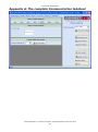
1
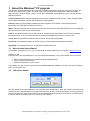
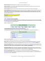
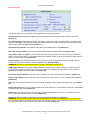
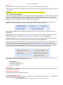
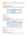
Trovan USER MANUAL LID650/665 stationary decoder READ THIS MANUAL FIRST Date: November 2010 Copyright: Dorset identification B.V. Tel. +31 (0)543 477119 Fax +31 (0)543 475355 Email: [email protected] www: http://www.dorset.nu User manual LID650/LID665 Contents CONTENTS ............................................................................................................................................................................ 2 1 ABOUT THE WINDOWS® PC PROGRAM ............................................................................................................... 3 1.1 HOW TO INSTALL THE SOFTWARE? ............................................................................................................................ 3 1.2 START THE SOFTWARE ............................................................................................................................................... 3 1.2.1 Global functions of the software ....................................................................................................................... 4 1.2.2 Communication tabsheet ................................................................................................................................... 5 1.2.3 The Settings tabsheet......................................................................................................................................... 6 1.2.4 The DBase tabsheet .......................................................................................................................................... 9 1.2.5 The History tabsheet ....................................................................................................................................... 11 1.2.6 The Trovan Flex tabsheet................................................................................................................................ 12 1.2.7 The Passwords tabsheet .................................................................................................................................. 13 1.2.8 The Upgrading tabsheet .................................................................................................................................. 13 2 FIRMWARE APPLICATION FLOW ....................................................................................................................... 14 3 ABOUT THE LID665V41 DECODER ....................................................................................................................... 15 3.1 SPECIFICATIONS LID665V41 .................................................................................................................................. 15 3.2 CONNECTABLE ANTENNAS ...................................................................................................................................... 15 3.3 HOW TO CONNECT THE LID665V41 ......................................................................................................................... 16 3.3.1 Description of connectors ............................................................................................................................... 16 3.4 LID665V20 BACKPLANE CONNECTIONS .................................................................................................................. 17 4 ABOUT THE LID650V40 DECODER ....................................................................................................................... 20 4.1 SPECIFICATIONS LID650V40 .................................................................................................................................. 20 4.2 CONNECTABLE ANTENNAS ...................................................................................................................................... 20 4.3 HOW TO CONNECT THE LID650V40 ......................................................................................................................... 21 4.3.1 Description of connectors ............................................................................................................................... 21 5 POWERSUPPLY LID650 & LID665: ........................................................................................................................ 23 6 COMMUNICATIONS ................................................................................................................................................. 24 6.1 RS232 SERIAL COMMUNICATION ............................................................................................................................. 24 6.2 RS485 NETWORK COMMUNICATION ........................................................................................................................ 24 6.2.1 RS485 bus general: ......................................................................................................................................... 24 7 FREQUENTLY ASKED QUESTIONS ...................................................................................................................... 26 APPENDIX A: THE COMPLETE COMMUNICATION TABSHEET .............................................................. 27 APPENDIX B: THE COMPLETE SETTINGS TABSHEET ............................................................................... 28 APPENDIX C: THE COMPLETE DBASE TABSHEET ....................................................................................... 29 APPENDIX D: THE COMPLETE HISTORY TABSHEET ................................................................................. 30 APPENDIX E: THE COMPLETE TROVAN FLEX TABSHEET ....................................................................... 31 APPENDIX F: THE COMPLETE PASSWORDS TABSHEET.......................................................................... 32 APPENDIX G: THE COMPLETE UPGRADING TABSHEET .......................................................................... 33 APPENDIX H: CHARACTERS THAT CAN BE USED AS PRE- OR SUFFIX (ONLY RS232). ....... 34 Dorset Identification b.v. Reserves the rights to change specifications without prior notice 2 User manual LID650/LID665 1 About the Windows® PC program ® The decoder is standard delivered with a Windows 95/98/NT/XP/Vista/7 based PC program to configure the decoder so it fits the user‟s needs. The main screen of the PC program is divided into 7 tabsheets called Communication, Settings, Dbase, History, Trovan Flex, Passwords, and Upgrading. These 7 groups have the following functions: Communication: Making settings regarding communication between decoder and PC. These settings include communication baudrate, transmit options and unit number settings. Settings: Making general settings regarding the basic operation of the reader. These settings include transponder list, read options and decoder options. DBase: When the decoder has to function as an access control system, this tabsheet allows you to manage the persons that have access to the controlled area. History: This tabsheet allows you to select whether the transponder codes have to be saved in the readers' historical memory or not. The historical data can also be downloaded and printed or saved to a file. Trovan Flex: This tabsheet contains all options to write Trovan Flex transponders. Passwords: This tabsheet contains an option to ask for a password before starting the software. Upgrading: This tabsheet allows you to upgrade the reader‟s firmware. 1.1 How to install the software? The software is delivered on cd, or you can download the latest software from our website: www.dorset.nu Software on CD: Insert the CD in your CD-ROM device. The CD will start automatically. If not, run RunHTML.exe from the CD Select “Install LID650-665 PC software Windows 98/NT/2000/XP” At pop up screen select “Open” Follow the instructions on your screen. The software can also be found under directory LID650&LID665\SOFTWARE on the CD. This can be copied to disk or CD for further use. 1.2 Start the software After the software has been installed an icon is created in the START menu. When the program is executed, the comport has to be selected where the program should search for the connected decoder(s). It is also possible to connect using the last used communication type and baudrate by depressing the open button. After depressing the search button the program will try to connect to the reader(s). Dorset Identification b.v. Reserves the rights to change specifications without prior notice 3 User manual LID650/LID665 If no reader is found the following message box will appear: Please take a look at our Frequently asked questions to solve communication issues. 1.2.1 Global functions of the software At the right side of the screen, a column of buttons is shown. The functions of these buttons will be explained here: RS485 unitnumber (network protocol only): All connected unit numbers will be available in this combo box. Here you can select a unit to change its settings. It is possible to check the amount of connected units by holding the mouse-arrow on RS485 unitnumber and wait until the hint appears. Get current settings: Get the current settings of the connected decoder. Set new settings: Depress this button to set the new settings to the selected decoder. Set settings to all (network protocol only): If more units are connected, this button can be used to set settings to all connected units. Export settings: With this button it is possible to make an export file (*.xml) of the current settings. For example to create a backup of the current settings. Dorset Identification b.v. Reserves the rights to change specifications without prior notice 4 User manual LID650/LID665 Import settings: With this button it is possible to import a settings file (*.xml). Software trigger: If the software trigger option is checked in the software, this button can be used to give a software trigger to start the readcycle. Select comport: Disconnects the current used comport and opens the select comport screen again. Disable RS485 Rx (network protocol only): By using this button, the RS485 receiver side of the units can be switched off. This can be used in large setups to prevent units from stopping the reading sequence to check communication. The receiver of the decoder can be turned on again by disconnecting the power from the units and power them up again. Reset reader: Reset the unit to factory defaults. WARNING! All the current settings will be lost Exit: Closes the software 1.2.2 Communication tabsheet The communication settings tabsheet allows you to change the communication baudrate, transmit options and the RS485 unit number. A complete overview of the communication settings tabsheet can be found in Appendix A: The complete Communication tabsheet. RS232 / RS485 Baudrate The RS232/RS485 communication speed can be adjusted here. To apply the new settings the Set new settings button has to be pressed The RS232 decoder defaults to 9600 baud after a reset. The RS485 decoder defaults to 19200 baud. RS232 Transmit options This part of the settings tabsheet allows you to change some transmit options. Send code: If a transponder code is read it can be transmitted via RS232/RS485 immediately by setting this checkbox. For RS232 the code can be transmitted together with a prefix, suffix or checkdigit. (default on) Send Prefix (RS232 only): The prefix in the editbox is sent in front of the transponder code. This option is only selectable when Send code is selected. Additional control characters can be applied by using the codes listed in Appendix H: Characters that can be used as pre- or suffix (only RS232).(default off) Send Suffix (RS232 only): The suffix in the editbox is sent behind the transponder code. This option is only selectable when Send code is selected. Additional control characters can be applied by using the codes listed in Appendix H: Characters that can be used as pre- or suffix (only RS232). (default off) Send checkdigit (RS232 only): A checkdigit is sent between the transponder code and the suffix. This checkdigit can be added to check if the transponder code is sent correctly. This option is only selectable when Send code is selected. (default off) Dorset Identification b.v. Reserves the rights to change specifications without prior notice 5 User manual LID650/LID665 Change unit number (RS485 only) Every RS485 decoder must have its own unit number so communication to this specific decoder can be established. The factory default unit number is 00 and can be renumbered by entering a new unit number between 1 and 254. When pressing „Set unit number‟ the new unit number will be assigned. After this the program will try to reconnect to all readers. 1.2.3 The Settings tabsheet To configure the reader to your requirements, you can adjust the settings in this tabsheet. This tabsheet allows you to adjust Transponder list, Read options and the Decoder options. The full settings tabsheet is shown in Appendix B: The complete Settings tabsheet. Transponder list Different transponder types can be enabled or disabled in this list. If the reading of more than one transponder type is enabled, the readcycletime will increase. This results in less reading speed. Read options Use all ID codes: Selected transponders will be read and used for saving, sending, access control etc (default on). Use only new ID: When a transponder is read more than once in a row, it will only be used once for saving, sending, access control, etc. A different transponder code has to be read first before the first transponder will be used again (default off). Use readdelay: A transponder code will be used only once for saving, sending, access control, etc. unless the specified time in the edit box has expired. After the readdelay has passed or when another transponder code has been read, the same transponder code can be used again (default off). (This is not time in seconds, but it stands for the number of readcycles) Check in/Check out: This is a combination of Use only new ID and Use readdelay. In this mode, a new transponder code is transmitted via RS232. As long as the transponder stays within range, nothing happens. If the transponder is no longer within range the 0000000000<CR> message is transmitted to the PC after readdelay time has passed. If the checkbox Use relay is activated the relay is activated during the time the tag is present. If Use access control is also active, then only those transponder code(s) present in the internal memory will activate the relay (default off). WARNING! The waittime after read must be > 0 Use sensor in/out: This option is not available on older decoder boards. In case of an older board, this option is invisible. Use this mode if in/out sensors are connected to the decoder board (see Chapter 5 and 6 for more information on how to connect in/out sensors to the decoder board). When one of the sensor inputs become high (5V) the reader starts the readcycle. When the option Save all movements is not enabled, both sensor Dorset Identification b.v. Reserves the rights to change specifications without prior notice 6 User manual LID650/LID665 inputs must become high in order to store the data in the reader‟s memory. The diagrams on the next page shows an example. Use the option Use IR sensors in combination with IR LED‟s who are controlled by the LID65x hardware (special hardware) (default all off). The antenna will always be turned off after the transponder is read, independent of the sensor states! The read delay has the following purpose: When using a tube with sensors on the both ends of the tube, it is possible that an outgoing animal does not trigger the outside sensor before leaving the inside sensor. Therefore the reader must continue reading for a small time. Depending on the length of the tube and the size of the animal this time must be shorter or longer. You can adjust this time in the box right next to the “Use sensor in/out” text. A valid “IN” sequence example: An animal enters the tube, triggering the sensor on the outside, then it travels through the tube where the transponder will be read. Eventually the animal will trigger the inside sensor and the event will be stored into the reader‟s memory. Wait time after read Start of new cycle Sensor outside Sensor inside Transponder read “Sensor in” must get high within this time frame (“Sensor out” high time + read delay time) Antenna < “sensor out” time > < Read delay > < The reader will save the “IN” event together with the transponder code. Note: The transponder may be read prior to the inside sensor getting high. In that case, the antenna will be turned off and the reader will continue waiting for the outside sensor to get high. The “Wait time after read” will start as soon as a transponder has been read and the sensors both have been high. After this time, both sensors must be low, if not the reader will turn the led on and off until these inputs are low. If the reader failed to read a transponder then it will save a null code into memory If the option “save all movements” is enabled then the reader also stores the events where only one sensor was triggered. Use Software trigger: The decoder starts reading a specified number of read cycles when the software trigger command has been received by the decoder. The trigger command can be send by clicking the Software Trigger button. The number of read cycles is specified in the edit box (default off). Use Hardware trigger: The decoder starts reading the specified number of read cycles after the hardware trigger has been occurred. For more information on the trigger input, please refer to the specifications regarding the decoder. The number of read cycles is specified in the edit box (default off). Dorset Identification b.v. Reserves the rights to change specifications without prior notice 7 User manual LID650/LID665 Decoder options The general settings of the decoder can be adjusted in this part of the screen. Use LED during read: When the LED has to flash during the read cycle, this option should be activated (default on). sec. waittime after read: After the decoder has read a transponder code, the reader waits x seconds before starting to read again. The waittime can be set between 0 and 25 seconds. During this time the LED can be lit and the relay output can be activated (default 0,1). Use LED during waittime: The LED can be lit during the waittime after read (default on). Use relay during waittime: The relay can be activated during the waittime after read (default off). Copy status relay 1 to output 2: If the optional secondary relay is placed, this option will copy the status of relays 1 to the second relays. In combination with V8xx firmware, output 2 can be configured as PWM output in order to control a RC-servo (default off). Output 2 setup: (only visible with V8xx firmware) Output 2 can be configured as Relays or PWM output, to control a RC-servo (for example to control a Rodent door) (default Relays). WARNING! Do not turn on the PWM mode if a relays is connected to OUTPUT 2! PWM output settings: (only visible if PWM mode was selected in the Output 2 setup) the angle of the RCservo can be changed by changing the values in the editboxes. Swapping of these values can be done by depressing the button next to the editboxes (default off). Use buzzer during waittime: By checking this checkbox, the buzzer will beep during waittime (default on). Read during waittime: (only visible with V8xx firmware) Force the reader to continue reading during waittime (default off). Use LCD: This checkbox should be set if the optional LC display has to display the transponder code (default off). Relay continuously on: This checkbox should be set if the relay has to be activated continuously, independent of a transponder was read (default off). Antenna on: The antenna can be turned on/off by selecting/deselecting this option. The decoder will not be able to read a tag if the antenna is turned off (default on). Fast mode (only for multicoil antennas such as the ANT610, ANT611 and ANT612): WARNING! This option can only be used with certain antennas. Contact your distributor if you are not sure! If the connected antenna can handle the fast mode, this checkbox can be set to put it into the fast reading mode. All single coil antennas are forced into fast mode automatically (default off). Dorset Identification b.v. Reserves the rights to change specifications without prior notice 8 User manual LID650/LID665 1.2.4 The DBase tabsheet When the reader will be used as an access control system, the configuration can be set in this tabsheet. The complete DBase tabsheet is shown in Appendix C: The complete DBase tabsheet. The Use access control checkbox has to be set if the reader is going to be used as access control reader (default off). The following information is shown in this tabsheet: Number of access codes: This is the number of transponders present in the memory at the moment the settings were acquired from the decoder. Dbase filename: Since you have the possibility to connect more than one reader to the PC, there are different databases that can be used for each decoder. Here you can see which database is currently used. Cardholder information: This information is shown in two ways: in a number of edit boxes, see Individual card holder information table form: Goldcard, Silvercard and records, see Goldcard and Silvercard. Search Topic: If you are looking for a certain item in the table, you can use this item to easily retrieve the required information. Just select the topic where you want to search in, for example Memo, and enter the search criteria in the Search on field. The following buttons are shown at the bottom of this tabsheet: Start new Dbase Creates a new empty table Get new codes Appends the ID cards which were entered via the Goldcard option in the current table. Print DBase Transfers data from the current table to a printer. Load DBase from file This allows the user to fill the table with information from a (*.key) file, the file open dialog will be opened after depressing this button. A file can be selected in this dialog. Save DBase to file After modifications are made in the table, this button should be pressed to store the altered information in a (*.key) file. The store file dialog will be opened to allow the user to enter a new file name if necessary. Dorset Identification b.v. Reserves the rights to change specifications without prior notice 9 User manual LID650/LID665 Clear Reader All information in the reader is erased. No cardholder can enter the controlled area. WARNING! All access codes and history codes will be lost! Save DBase to reader The current contents (active cards only) of the table will be transferred to the reader that is currently selected. Individual card holder information The Activated checkbox should be set if the current record has to be stored in the readers memory as a valid access code, after the Save Dbase to reader button is pressed. Information in Table form In this part of the screen a list is shown of the records that are present in the selected database file. With the horizontal scroll bar the type, code etc. can be made visible. With the vertical scroll bar you can walk through the records. Special in this table are the first and second record. The first card in the table is defined as the Goldcard and the second as Silvercard. Goldcard The first card in the table is the Goldcard, a normal transponder with a special function. After reading the Goldcard, the reader will automatically be set in the Save mode. All ID numbers that are read from now, are stored in the internal memory of the decoder as valid access cards. After reading the Goldcard again, the reader will return to the normal operation mode. Dorset Identification b.v. Reserves the rights to change specifications without prior notice 10 User manual LID650/LID665 Silvercard The second card in the table is the Silvercard, a normal transponder with a special function. After reading the Silvercard, the reader will erase all ID numbers from the internal memory, except for the Goldand Silvercard. WARNING! There will be no valid access card after this ID number has been read. 1.2.5 The History tabsheet The reader is capable to save max. 12800 transponder codes without date/time or 6400 transponder codes with date/time (1024kB EEPROM are optional available, default a 512kB EEPROM is mounted). The maximum number of codes in the historical memory will decrease when the access control option is used. The full History tabsheet is shown in Appendix D: The complete History tabsheet. Whether the ID codes should be stored can be set in this tabsheet. There are different ways of storing the information in the internal memory. This can be configured by the following checkboxes: Save codes in reader: Select this option if the decoder has to save the ID codes in the historical memory (default off). With date/time: If the reading date and time have to be saved together with the ID code this option has to be selected. This option is only enabled if the Save codes in reader option is selected (default off). Overwrite codes: When the historical memory is full the reader can overwrite the oldest codes or it can stop saving codes. If this option is selected the oldest codes will be overwritten (default on). Other information shown in this tabsheet is the number of saved codes present in the historical memory at the moment the settings were acquired from the decoder by depressing the Get current settings button. This number of overwritten codes is only displayed if the Overwrite codes box is selected. This number represents the number of codes that are overwritten in the historical memory after the memory went full. The number of overwritten codes will be determined at the moment all history codes are downloaded to the PC. The historical data can be downloaded from the decoder to the table by clicking on the Get codes from reader button. Other functions of the History tabsheet are: Clear Reader Clear history database Save history database to file Print history database Clear Reader The readers memory will be erased after this button has been pressed. The information stored in the reader is lost and cannot be retrieved. Clearing history database Pressing this button clears the data in the table. Save history database to file The file save dialog is opened after this button is pressed. The information stored in the file is “;” separated and can be loaded by a spreadsheet program. Dorset Identification b.v. Reserves the rights to change specifications without prior notice 11 User manual LID650/LID665 Print history database The printer dialog is opened, and the information in the table will be transferred to the selected printer after this button has been pressed. Sorting After the information is downloaded from the reader, the table can be sorted on a certain item like code, date or time. To do this, just click on the column title on top of the table. If the table should be sorted in inverted manners press on the column title again. Filtering Filtering an item in the table can be done by selecting the desired topic and enter your filter criteria in the "search on" input field. The table will be updated immediately after each character entered in the input field. If you press the Print history database or Save history database to file button after you have filtered information from the table, only the filtered information will be printed or saved. 1.2.6 The Trovan Flex tabsheet In the Trovan Flex tabsheet, all the options are available to program Trovan Flex transponders. The full Trovan Flex tabsheet is shown in Appendix E: The complete Trovan Flex tabsheet. String to send A string of maximal 15 characters can be sent to a read-write transponder. Only LID665 decoders with version L665V200 or later can write read-write transponders. Write string to RW transponder Sends the string to a read-write transponder. Dorset Identification b.v. Reserves the rights to change specifications without prior notice 12 User manual LID650/LID665 Number of blocks Here the number of blocks for a read-write transponder can be set. A 3 blocks read-write transponder can store up to 5 characters, a 5 blocks 10 characters and a 7 blocks read-write transponder can store up to 15 characters. Set number of blocks This sets the number of blocks for a read-write transponder. 1.2.7 The Passwords tabsheet In the passwords tabsheet, an optional startup password can be set. If no new password was entered, the software won't ask for a password at startup. The full window is shown in Appendix F: The complete Passwords tabsheet. Old password Field to enter the old password. New password Field to enter a new password. New password verification Extra field to enter the new password for verification. 1.2.8 The Upgrading tabsheet With the upgrading tabsheet it is possible to upload a newer firmware version to the decoder. This is possible from firmware version 710 or higher. The complete Upgrading tabsheet is shown in Appendix G: The complete Upgrading tabsheet. Filename This field shows the current selected filename. This can be changed by pressing the browse button. Browse button Button to open a *.EHX or a *.AEH file, depending on the current firmware version. Upload firmware to unit Upload the new firmware to the currently selected unit. Upload firmware to all units If the software is connected via a RS485 interface to more than one decoders, it is possible to upload new firmware to all current connected decoders. Dorset Identification b.v. Reserves the rights to change specifications without prior notice 13 User manual LID650/LID665 2 Firmware application flow A concise version of the decoders application flow is shown here: Dorset Identification b.v. Reserves the rights to change specifications without prior notice 14 User manual LID650/LID665 3 About the LID665V41 decoder The LID665V41 decoder is designed for use with single coil antennas like the ANT613(S)/ANT614/614OEM or custom made antennas. The standard decoder together with an antenna can read all Trovan™ read-only and Flex read-write transponders. Standard the LID665V41 decoder is delivered with Windows® XP/Vista/7 PC software to change the settings of the decoder, download the history data or assign access codes. 3.1 Specifications LID665V41 Dimensions decoder Weight decoder Supply voltage Supply current 51 x 50 x 8 mm 20 Gram +5VDC +/- 5% or +7,5VDC to 24VDC 70mA (antenna activated) 26mA (antenna deactivated) Reading rate 24 msec Operating frequency 128 kHz Number of ID codes with 6400 ID codes only or 3200 with date and time 32kB EEPROM Interfaces and protocols RS232 (8 data, no parity, 1 stop, 1200..57600 baud, default 9600) RS485 2-wire (8 data, no parity, 1 stop, 1200..57600 baud, default 19200) LED and buzzer output DC buzzer type (5VDC) Options Clock/Calendar with lithium battery to store date/time with ID-codes. Up to 1024kB memory for storing 25600 codes or 12800 with date and time. I2C connection for serial communication Custom serial communication. 2 TTL inputs or outputs. 3.2 Connectable antennas Reading distances chart (distance in cm) Antenna ANT614W ANT614S ANT614OEM ANT613 ANT613S Dimensions 124x76x23mm 120x45x23mm 85 x 55 x 2mm Ø18 x 165mm Ø20 x 60mm Weight 200 gram 140 gram 10 gram 60 gram 50 gram Transponder types Protection optional IP67 protection optional IP67 protection NA IP65 IP65 ID100 2 2 2 1 1 ID200 5 5 5 2,5 2,5 ID300 3,5 3,5 3,5 1,7 1,7 ID400 11 11 11 6 6 Several other complete and OEM customized antenna can be made on request. Please visit our website for more information. http://www.dorset.nu WARNING! Metal objects near the antenna increase the current consumption and reduce the reading distance. The minimum distance towards a metal surface depends on the type of antenna. Also (SVGA) monitors or switched mode power-supplies can decrease the reading distance. Dorset Identification b.v. Reserves the rights to change specifications without prior notice 15 User manual LID650/LID665 3.3 How to connect the LID665v41 3.3.1 Description of connectors J101 powersupply 1. 7-24VDC 2. +5VDC +/- 5% 3. GND, Ground J104 Serial port 1. TXD RS232 (9600,n,8,1*) 2. RXD RS232 (9600,n,8,1*) 3. RS485 B (19200,n,8,1*) 4. RS485 A (19200,n,8,1*) 5. GND, Ground Important note Depending on firmware version Vx.xx or Nx.xx, RS232 or RS485 is available. J103 Output LED/Buzzer 1. + led 2. – led 3. + buzzer (DC 20mA) 4. – buzzer Important note J102 I2C Output 1. SDA, serial DATA 2. VCC 3. GND 4. SCL, serial Clock J105 Input/output 1. Output 1 2. Input 1, used for in/out sensors or hardware trigger J108 Input/output 1. Output 3, for customized firmware only 2. Output 2, used with PWM controlled RC-servo 3. Input 2, used for in/out sensors If you connect an inductive load like an electric strike or relay, there should be a free running diode (like 1N400x type) mounted at the inductive load. JP1 Bus-end for RS485 bus (close if decoder is at the bus-end). Resistors of 680 Ohm must be placed between J101.2 and J104.3 and between J104.4 and J104.5 at one of the bus-end for RS485 communication. Grounding has to be connected between every unit for RS485 If you use the in/out sensors use pull up or pull down resistors for the sensors (depending on the sensor type). * = Baudrate can be changed by software setting (1200, 2400, 4800, 9600, 19200, 38400 and 57600 baud) J106 Antenna connection: 1. + single coil antenna 2. - single coil antenna IMPORTANT NOTE! Use a 125mA fuse in line with the 5V power input Use a max. 500mA fuse in line with the wide range input. There are no fuses on the LID665 OEM decoder board JP1 Bus-end for RS485 bus must be closed if decoder is at the end of the bus. Resistors of 680 ohm must be placed between J101.2 and J104.3 and between J104.4 and J104.5 at one of the bus-ends. Dorset Identification b.v. Reserves the rights to change specifications without prior notice 16 User manual LID650/LID665 3.4 LID665v20 Backplane connections The LID665 decoder can be combined with the LID665V20 backplane that contains connectors, two fuses, a buzzer and a potential free relay output to drive an electric lock. J1 Powersupply 1. 7-24Vdc Power supply (Vin High) 2. 5Vdc +/-5% Power supply (Vin LOW) 3. GND J2 Communication 1. Txd Transmit data RS232 2. Rxd Receive data RS232 3. B channel RS485 4. A channel RS485 5. B channel RS485 6. A channel RS485 7. GND J19 Antenna connection 1. Antenna signal 2. Antenna GND J18 External LED 1. + LED 2. – LED J20 Relay output 1 1. voltage, 5V or wide range, jumper J12 selectable. If jumper removed relay1 can be used to switch up to 125VAC, max. 1 Amp. 2. NO Normally Open 3. NC Normally Closed 4. GND J8 Input/Output direct from uP 1. TTL signal Output 2, used with PWM controlled RC-servo 2. TTL signal for Input 2, used with in/out sensors 3. GND J6 Input/Output direct from uP 1. TTL signal Output 1 2. TTL signal for input 1, used with in/out sensors 3. GND J16 Input for hardware trigger 1. TTL signal for Input 3. Used in combination with customized firmware 2. GND Important note J14 I2C Serial Bus 1. SDA Serial Data 2. VCC 3. GND 4. SCL Serial Clock J9 Relay output 2 1. voltage, 5V or wide range, jumper J11 selectable. If jumper removed relay2 can be used to switch up to 125VAC, max 1Amp. 2. NO Normally Open 3. NC Normally Closed 4. GND If you connect an inductive load like an electric strike or relay, there should be a free running diode (like 1N400x type) mounted at the inductive load. JP1(on decoder) Bus-end for RS485 bus (close if decoder is at the bus-end). Resistors of 680 Ohm must be placed between J1.2 and J2.3 and between J2.6 and J2.6 at one of the bus-end for RS485 communication. Grounding has to be connected between every unit for RS485 If you use the in/out sensors use pull up or pull down resistors for the sensors (depending on the sensor type). Dorset Identification b.v. Reserves the rights to change specifications without prior notice 17 User manual LID650/LID665 Schematic overview of Relay outputs Use of jumper J11(optional) &12 The two jumpers can be used in three different ways. 1. No jumper: External voltage can be applied to pin 1 of J20/J9 max 1A, max 150Vac (See table below) 2. Jumper on 1-2: Vin LOW is selected. 3. Jumper on 2-3: Vin HIGH is selected. Switching current vs voltage Switching voltage Switching current 30 VDC 65 VDC 150 VAC 1A 460 mA 460 mA Dorset Identification b.v. Reserves the rights to change specifications without prior notice 18 User manual LID650/LID665 In/out sensor connections Connect the sensors to input 1 and input 2. NOTE: Use pull-up or pull-down resistors for the sensors (depending on the sensor type) Never exceed VCC (5Volts) on the sensor input pins Dorset Identification b.v. Reserves the rights to change specifications without prior notice 19 User manual LID650/LID665 4 About the LID650V40 decoder The LID650V40 decoder is designed for use with multiple coil antennae like the ANT610, ANT610F, ANT611 and ANT612 antenna. Together with antenna driver TM613 it is possible to connect a single coil antenna. The standard decoder together with an antenna can read all Trovan™ read-only and Flex read-write transponders. Standard the LID650V40 decoder is delivered with Windows® XP/Vista/7 PC software to change the settings of the decoder, download the historical data or assign access codes. 4.1 Specifications LID650V40 Dimensions decoder Weight decoder Power supply Reading rate Operating frequency Number of ID codes Interfaces and protocols Standard delivered with Options 4.2 100 x 58 x 16 mm 45 Gram 12VDC +/- 5%, average 200mA, peak 700mA (Depending on connected antenna) 24 msec. 128 kHz 6400 codes only or 3200 with date and time RS232 (8 data, no parity, 1 stop, 1200..57600 baud default 9600) RS485 2-wire (8 data, no parity, 1 stop, 1200..57600 baud (default 19200) Buzzer Screw connectors to connect antenna, power i.e. Clock/Calendar with lithium battery to store date/time with ID-codes Up to 1024kB memory for storing 25600 codes or 12800 with date and time I2C connection for serial communication Custom serial communication 2 TTL inputs or outputs Connectable antennas Reading distances chart (distance in cm) Antenna ANT610F ANT611 ANT612 Dimensions 215 x 185 x 25 mm Ø50 x 165mm 405 x 405 x 35 mm Antenna 1,6 Kg 0,5 Kg 4,5 Kg Transponder types Dimensions optional IP67 IP65, optional IP67 IP54, optional IP67 ID100 18 7 35 ID200 28 17 50 ID300 20 10 40 ID400 40 25 80 With the optional TM613 single coil antenna driver it is also possible to connect single coil antennas like the ANT613, ANT614 and custom made antennas. Please visit our website (http://www.dorset.nu) for more information. WARNING Metal objects near the antenna increase the current consumption and reduce the reading distance. The minimum distance towards a metal surface depends on the type of antenna. Also (SVGA) monitors or switched mode power-supplies can decrease the reading distance. Dorset Identification b.v. Reserves the rights to change specifications without prior notice 20 User manual LID650/LID665 4.3 How to connect the LID650v40 4.3.1 Description of connectors J104 Multi coil antenna connector 1. Shield data signal 2. White, data signal 3. Brown, 12VDC antenna 4. Pink, GND antenna 5. Blue, synchronization signal 6. Yellow, Txon antenna on/off signal J103 LED/Input connector 1. + Led, (green wire antenna ANT610) 2. -Led, (Grey wire antenna ANT610) 3. Input 1, TTL level used for in/out sensors and hardware trigger 4. Input 2, TTL level used for in/out sensors J100 Power supply (VCC) 1. 12VDC +/- 5% regulated, 1 Amp. 2. GND J401 Potential free relay output 1. Potential free output (or 12VDC if JP3 closed) 2. NC, normally closed contact (12VDC if JP3 closed) 3. NO, normally open contact (12VDC if JP3 closed) 4. GND J107 TM613 Single coil driver connector Attach the optional TM613 single coil driver board to this connector J101 I2C Output 1. SDA, serial data 2. VCC 3. GND 4. SCL, serial clock Important note J106 I2C Output 1. Output 4, for customized firmware only 2. Output 3, for customized firmware only J403 Optional potential free relay output 1. Potential free output (or 12VDC if JP2 closed) 2. NC, normally closed contact (12VDC if JP2 closed) 3. NO, normally open contact (12VDC if JP2 closed) 4. GND J102 Communication port 1. TXD RS232 (9600,n,8,1*) 2. RXD RS232 (9600,n,8,1*) 3. RS485 B (19200,n,8,1*) 4. RS485 A (19200,n,8,1*) 5. RS485 B (19200,n,8,1*) 6. RS485 A (19200,n,8,1*) 7. GND, Ground If you connect an inductive load like an electric strike or relay, there should be a free running diode (like 1N400x type) mounted at the inductive load. JP1 Bus-end for RS485 bus (close if decoder is at the bus-end). Resistors of 2K7 Ohm must be placed between J100.1 and J102.3 and 680 Ohm between J102.6 and J102.7 at one of the bus-end for RS485 communication. Grounding has to be connected between every unit for RS485 If you use the in/out sensors use pull up or pull down resistors for the sensors (depending on the sensor type). * = Baudrate can be changed by software setting (1200, 2400, 4800, 9600, 19200, 38400 and 57600 baud) Important note Depending on firmware version Vx.xx or Nx.xx RS232 or RS485 is available. Dorset Identification b.v. Reserves the rights to change specifications without prior notice 21 User manual LID650/LID665 Schematic overview of Relay outputs Use of jumper J2 &J3 (optional) The two jumpers can be used in two different ways. 1. No jumper: External voltage can be applied to pin 1 of J20/J9 max 1A, max 150Vac (See table below) 2. Jumper on 1-2: VCC12 is selected. Switching current vs voltage Switching voltage Switching current 30 VDC 65 VDC 150 VAC 1A 460 mA 460 mA Dorset Identification b.v. Reserves the rights to change specifications without prior notice 22 User manual LID650/LID665 5 Powersupply LID650 & LID665: The powersupply can be used for 240Vac or 120Vac. When using 240Vac R1 has to be placed and fuse F1 is T125mA (slow type). When using 120Vac R2 and R3 have to be placed and fuse F1 is T250mA (slow type). J1: 240Vac/130Vac Power input 1. Protective earth ground 2. Neutral 3 120/240Vac J3: Output 12V 1. 12V 2. GND F1: Input fuse (slow type) T125mA fuse for 240Vac T250mA fuse for 120Vac. F2: Output fuse (fast type) F800mA fuse Dorset Identification b.v. Reserves the rights to change specifications without prior notice 23 User manual LID650/LID665 6 Communications The decoders can be connected to a PC or other devices directly via RS232 or via a network using a 2-wire RS485 connection. The type of communication to be used depends on the firmware inside the decoder. 6.1 RS232 serial communication The direct RS232 connection is the easiest way to connect a decoder to the PC. It is especially used for applications with a low number of readers (1..4). The RS232 communication can only be used if a decoder is situated close to the PC (up to 14 meters / 46ft). PC Decoder 1 Decoder 2 Decoder 3 6.2 RS485 network communication A 2-wire RS485 network connection is necessary when larger numbers of decoders have to be connected via the same communication port on the PC, or when the distance between decoder and PC is too far for a direct RS232 connection. Decoder 1 Uport Decoder 2 Decoder 3 Up to 32 units PC The LID665N decoders and the LID650N decoders can be used together in the same RS485 network. 6.2.1 RS485 bus general: The total bus length may not exceed 1200 meters (4000ft). All decoders in the RS485 bus are connected by a RS485 compatible shielded twisted pair cable. The voltage over the A and B lines has to be between 0,2 to 0,4 Volts. The ground of all the decoder have to be connected. Decoder: 1, first in the bus The first unit in the bus has fail safe resistors and the 120 Ohm Jumper set. The resistors of 2K7 Ohm must are placed between VCC12 (or 680 Ohm between the VCC5) and the B line and 680 Ohm between GND and the A line. The first decoder on the bus needs a termination resistor. This resistor is already available on the decoder and can used by placing the jumper JP3 on the decoder board. Conversion from RS485 to USB by Uport (Moxa Uport 1130) The Uport is used to convert the RS485 data to USB. This device should be placed somewhere between the first and last decoder in the bus. Dorset Identification b.v. Reserves the rights to change specifications without prior notice 24 User manual LID650/LID665 The UPort 1130 comes with a DB9 to terminal block converter, with pin assignments as shown below: Terminal Block Pin 1 2-wire RS485 - 2 - 3 4 5 Data+(B) Data-(A) GND Follow the U-port instructions to install the Uport! Decoder: 2,3…n-1 The bus has to go from decoder to decoder. Do not use branches from the bus to a decoder but make the connection on the decoder itself. The maximum number of decoders on each bus is 32. Multiple RS485 busses can be used with only one PC. By using more RS485 adaptors like the Uport 1130. The 120 Ohm jumper JP3 is NOT set in these decoders. Decoder: n, last in the bus The decoder on the end of the bus needs a termination resistor. This resistor is already available on the decoder and can used by placing the 120 Ohm termination jumper on the decoder board. Dorset Identification b.v. Reserves the rights to change specifications without prior notice 25 User manual LID650/LID665 7 Frequently asked questions q: The LED in the antenna flashes very fast a: The reader is probably in save mode, read the Goldcard once more or use the PC software q: A card is not recognized as a valid keycard. a: Make sure the checkbox use access control is set, the reader is not in the save mode and the active checkbox is set. q: The reader is not recognized at start up time a: Make sure the RS232/RS485 connection is made properly and that the reader is powered. q: The activation time of the relay is to short or to long a: Check the value of the wait time after read, perhaps you'll have to reconfigure this value. q: An ID number is only transmitted once, I need it more often a: Check in the Read options if the Use all ID codes or Use readdelay checkbox is checked. q: I choose a new Transmit option but the reader doesn't seem to apply the new settings a: After the settings have been changed, you should depress the Set new settings button on the right side of the screen otherwise the new settings are not being used. Make sure the reader isn‟t in the Disable RX mode by repower it. q: Although the reader scans the tag, the LED does not show the readcycle. a: The checkbox Use LED during read is not set. q: The LID665 reader doesn‟t write a read-write transponder: a: Probably the transponder is too far away from the antenna or distance to another reader is too small. Dorset Identification b.v. Reserves the rights to change specifications without prior notice 26 User manual LID650/LID665 Appendix A: The complete Communication tabsheet Dorset Identification b.v. Reserves the rights to change specifications without prior notice 27 User manual LID650/LID665 Appendix B: The complete Settings tabsheet Dorset Identification b.v. Reserves the rights to change specifications without prior notice 28 User manual LID650/LID665 Appendix C: The complete DBase tabsheet Dorset Identification b.v. Reserves the rights to change specifications without prior notice 29 User manual LID650/LID665 Appendix D: The complete History tabsheet Dorset Identification b.v. Reserves the rights to change specifications without prior notice 30 User manual LID650/LID665 Appendix E: The complete Trovan Flex tabsheet Dorset Identification b.v. Reserves the rights to change specifications without prior notice 31 User manual LID650/LID665 Appendix F: The complete Passwords tabsheet Dorset Identification b.v. Reserves the rights to change specifications without prior notice 32 User manual LID650/LID665 Appendix G: The complete Upgrading tabsheet Dorset Identification b.v. Reserves the rights to change specifications without prior notice 33 User manual LID650/LID665 Appendix H: Characters that can be used as pre- or suffix (only RS232). The prefix and suffix string can each be 4 characters long. All ASCII characters can be used except for the hexadecimal values 0Dh and 00h. The control characters, the hexadecimal values and the way to enter them in the prefix or suffixbox are shown below. CHARACTER NUL SOH STX ETX EOT ENQ ACK BEL BS TAB LF VT FF CR SO SI DLE DC1 DC2 DC3 DC4 NAK SYN ETB CAN EM SUB ESC FS GS RS US HEX 00h 01h 02h 03h 04h 05h 06h 07h 08h 09h 0Ah 0Bh 0Ch 0Dh 0Eh 0Fh 10h 11h 12h 13h 14h 15h 16h 17h 18h 19h 1Ah 1Bh 1Ch 1Dh 1Eh 1Fh HOW TO ENTER NOT ALLOWED <SOH> <STX> <ETX> <EOT> <ENQ> <ACK> <BEL> <BS> <TAB> <LF> <VT> <FF> NOT ALLOWED <SO> <SI> <DLE> <DC1> <DC2> <DC3> <DC4> <NAK> <SYN> <ETB> <CAN> <EM> <SUB> <ESC> <FS> <GS> <RS> <US> Dorset Identification b.v. Reserves the rights to change specifications without prior notice 34