1
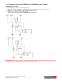
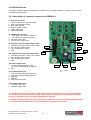
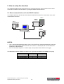
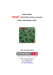
Installation manual trovan Access Guard DATE: 5 November 2008 Copyrights: DORSET IDENTIFICATION B.V. The Netherlands Tel. +31 543 477119 Fax +31 543 475355 Email : [email protected] www.dorset.nu Contents: CONTENTS: ...........................................................................................................................................................................2 1. INTRODUCTION ................................................................................................................................................3 2. GENERAL DESCRIPTION OF TROVAN ACCESS GUARD.....................................3 2.1 IDENTIFICATION LABELS ..................................................................................................................................................3 2.2 READERS .........................................................................................................................................................................3 2.2.1 Antenna ....................................................................................................................................................................3 2.2.2 Decoder....................................................................................................................................................................3 2.3 PC ...................................................................................................................................................................................4 2.3.1 RS232 communication .............................................................................................................................................4 2.3.2 RS485 communication .............................................................................................................................................4 3. TECHNICAL SPECIFICATIONS OF THE DECODERS. ..................................................5 3.1 LID665A DECODER AND LID665 BACKPLANE ................................................................................................................5 3.1.1 LID665A V2.X decoder and LID665A V3.X decoder...............................................................................................5 3.1.2 Description of connector connections LID665BPv14 / LID665BPv20 Backplane..................................................6 3.1.3 Schematic overview of LID665BPv14 / LID665BPv20 relay outputs: ....................................................................7 3.1.4 How to connect: .......................................................................................................................................................8 3.2 LID650A DECODER .........................................................................................................................................................9 3.2.1 Description of connector connections LID650v3.0 .................................................................................................9 3.2.2 How to connect: .....................................................................................................................................................10 4. POWERSUPPLY LID650 & LID665: .................................................................................................11 5. HOW TO SETUP THE DECODERS ..................................................................................................12 5.1 DIRECT COMMUNICATION VIA 3-WIRE RS232 INTERFACE .............................................................................................12 5.2 NETWORK COMMUNICATION VIA 2-WIRE RS485 INTERFACE.........................................................................................13 6. PC SOFTWARE ..................................................................................................................................................14 Dorset identification b.v. Reserves the rights to change specifications without prior notice 2 1. Introduction This manual contains the installation instructions for the trovan access guard system. Following subjects will be explained: • • • • General description of the trovan access guard system. Technical specifications of the decoders How to set-up the trovan access guard system Installation of the PC Software. 2. General description of trovan access guard. This chapter gives a brief explanation of all different components of the trovan access guard system. 2.1 Identification labels All trovan identification labels or transponders are guaranteed to be world-wide unique. This means that every identification number will be produced only once regardless to the type of transponder. The reading distance of each transponder depends on its size and shape. Reading distances up to 120cm (47 inch) can be achieved when the right combination between transponder and reader is used. 2.2 Readers The basic components of the entire system are the access control readers. Every reader consists of an antenna and a decoder. 2.2.1 Antenna When a transponder is held within the reading distance of the antenna, the transponder signals will be received by the antenna and are passed through to the decoder. Because the entire system is based on inductivity the antenna may not be placed upon or near to any metal. This will decrease readingdistance and can even destroy the antenna. 2.2.2 Decoder The decoder is the intelligent part of the reader. It calculates the actual identification code of the transponders and can perform different actions with these codes depending on the location of the decoder, date and time etc. Dorset identification b.v. Reserves the rights to change specifications without prior notice 3 2.3 PC The PC is used for making all the decoder settings. The PC can communicate with the decoders via its standard internal RS232 comport(s). Another option is using RS485 communication, which allows the decoders to be put in a network. Only connect one type of communication. 2.3.1 RS232 communication The direct RS232 connection is the easiest way to connect a decoder to the PC. It is especially used for access control systems with a low number of readers (1..4). The RS232 communication can only be used if a decoder is situated close to the PC (up to 14 meters / 46ft). Decoder 3 PC Decoder 1 Decoder 2 Figure 1: RS232 communication. 2.3.2 RS485 communication The 2-wire RS485 network connection is used when larger numbers of decoders are used or when the distance between decoder and PC is too far for a direct RS232 connection. A RS485 network connection requires a RS485 comport-card in the PC, which is normally not present in a standard PC. An external RS232 to RS485 converter can also be used. Decoder 1 PC Decoder 2 Decoder 3 Up to 31 units Figure 2: RS485 communication using internal RS485 port card. Decoder 1 RS232/RS485 converter Decoder 2 PC Figure 3: RS485 communication via RS232/RS485 converter. Dorset identification b.v. Reserves the rights to change specifications without prior notice 4 Decoder 3 Up to 31 units 3. Technical specifications of the decoders. This chapter describes the connections of the decoders LID665A and LID650A. 3.1 LID665A decoder and LID665 backplane The LID665A proximity decoder is designed for antennas with a reading distance up to 12cm (4.5 inch) with a creditcard size transponder. The decoder is placed on the LID665BP backplane, which contains the physical connections. 3.1.1 LID665A V2.X decoder and LID665A V3.X decoder LID665 V2.X LID665 V3.X R12 Note: Note: 1. JP1 Solder jumper must be closed when the 1. decoder is at the RS485 bus-end. See chapter 3.2 for more information regarding RS485. Jumper JP1 should also be set when using RS232 communication. 2. If you want to use the hardware trigger input, R12 should be removed. Dorset identification b.v. Reserves the rights to change specifications without prior notice 5 JP1 Solder jumper must be closed when the decoder is at the RS485 bus-end. See chapter 3.2 for more information regarding RS485. Jumper JP1 should also be set when using RS232 communication. J9 J6 J8 3.1.2 Description of connector connections LID665BPv14 / LID665BPv20 Backplane J1 J18 J2 J19 J20 J14 J16 = PIN1 J1 Powersupply 1. 7-24Vdc Wide range power supply (Vin High) 2. 5Vdc +/-5% stabilized power supply (Vin LOW) 3. Gnd J19 Antenna connection 1. Antenna signal 2. Antenna Gnd J18 External LED 1. + LED (red antenna LED +) 2. – LED (red antenna LED -) J2 Communication 1. Txd Transmit data RS232 2. Rxd Receive data RS232 * 3. RS485 B * 4. RS485 A 5. RS485 B (parallel to pin 3)* 6. RS485 A (parallel to pin 4)* 7. Gnd J9 Relay output 2 (Optional)** 1. Voltage, 5VDC (Vin LOW, max. 50mA) or wide range (Vin HIGH, max. 400mA), jumper J11 selectable. 2. NO Normally Open 3. NC Normally Closed 4. GND J16 Hardware trigger with internal pull up resistor 1. GND 2. TTL signal input 3, connect to GND to activate or leave open. ** J20 Relay output 1 1. Voltage, 5VDC (Vin LOW, max. 50mA) or wide range (Vin HIGH, max. 400mA), jumper J12 selectable. 2. NO Normally Open 3. NC Normally Closed 4. GND J8 Input/Output direct from uP 1. TTL signal Output 2 (parallel to relay output 2, Green antenna LED) 2. TTL signal for input 2 3. Gnd J6 Input/Output direct from uP 1. TTL signal Output 1 (parallel to relay output 1) 2. TTL signal for input 1 3. Gnd * For RS485 communication resistors of 680 ohm must be placed between J1.2 and J2.3 and between J2.6 and J2.7 at one of the bus-ends. Jumper JP1 must be set at both bus-ends (120 Ohm termination resistor) ** If jumper removed relay can be used to switch up to 125VAC, max. 1 Amp with external powersupply. If an inductive load is connected a free running diode has to be placed at the load. Dorset identification b.v. Reserves the rights to change specifications without prior notice 6 3.1.3 Schematic overview of LID665BPv14 / LID665BPv20 relay outputs: Use of jumper J11** &12 The two jumpers can be used in three different ways. • No jumper: External voltage can be applied to pin 1 of J20/J9 (Max. 125VAC, max. 1 Amp) • Jumper on 1-2: Vin LOW 5Vdc +/-5% is selected (Max. 50mA). • Jumper on 2-3: Vin High 7-24Vdc is selected (Max. 400mA, with EID part number. PWS12V-1A 12V/1000mA). Important note: If you connect an inductive load like an electric lock or relay, there should be a free running diode (like 1N400x type) mounted at the inductive load. Dorset identification b.v. Reserves the rights to change specifications without prior notice 7 3.1.4 How to connect: Connecting the Power supply: 1. Connect Vcc (7-30V regulated) to J1.1 2. Connect Gnd to J1.3 Connecting an antenna ANT614 (4 wires): 1. Connect the brown wire to J19.1 2. Connect the yellow wire to J19.2 3. Connect the green wire to J18.1 4. Connect the white wire to J18.2 Connecting an antenna ANT614W or ANT614S (6 wires): 1. Connect the brown wire to J19.1 (Antenna coil) 2. Connect the yellow wire to J19.2 (Antenna coil) 3. Connect the pink wire to J18.1 (antenna +5V) 4. Connect the green wire to J18.2 (red antenna LED) 5. Connect the blue wire to J8.2 (green antenna LED) Connecting RS232 communication: Only connect RS232 communication OR RS485 communication. Do NOT connect both 1. Connect the TX line to J2.1 2. Connect the RX line to J2.2 3. Connect the GND line to J2.7 Connecting RS485 communication: Only connect RS232 communication OR RS485 communication. Do NOT connect both 1. Connect the RS485 B line coming from the previous decoder to J2.3 2. Connect the RS485 A line coming from the previous decoder to J2.4 3. Connect the RS485 B line going to the next decoder to J2.5 4. Connect the RS485 A line going to the next decoder to J2.6 5. Connect the groundline to J2.7 6. When this decoder is the first or last on the bus then jumper JP1 should be set on the LID665. This jumper sets the termination resistor of 120 Ohm which is on the circuit board 7. When this decoder is the first on the bus, 2 resistors should be placed to get a predefined voltage on the bus. Place 680 Ohm between J2.3 and J1.2 (+5V) Place 680 Ohm between J2.4 and J2.5 (GND) Connecting the doorlock: 1. Set jumper J12 to use the on board power to switch the doorlock. If external power is used connect it to J20.1 and leave Jumper J12 open 2. Connect the lock to J20.2 when the lock is normally closed. Connect the lock to J20.3 when the lock is normally open. 3. Connect the GND of the doorlock to J20.4 Optional: When a hardware trigger is used follow the steps below. The sensor should turn low to trigger: 1. Connect the sensor output to J8.2 2. If necessary connect the Vcc and GND of the sensor. Optional: When a doorswitch is used to indicate a door ‘open’ alarm then follow the steps below. The sensor should turn low to indicate the ‘Door open’ status. 1. Connect the switch output to J8.2 2. If necessary connect the Vcc and GND of the sensor. Optional: Connecting an extra signal light or buzzer to output 2 (onboard relay 2 should be placed) 1. Set jumper J11 to use the on board power to switch the light or buzzer. If external power is used connect it to J9.1 and leave Jumper J11 open. 2. Connect the light or buzzer to J9.2 3. Connect the GND of the light or buzzer to J9.4 Dorset identification b.v. Reserves the rights to change specifications without prior notice 8 3.2 LID650A decoder The LID650 handsfree decoder is designed for antennas with a reading distance up to 80cm (31 inch) with a creditcard size transponder. 3.2.1 Description of connector connections LID650v3.0 J1: 1. 2. 3. 4. 5. 6. Antenna connector Yellow, Antenna on/off signal (TXON) Blue, synchronization signal Pink, GND antenna Brown, 12VDC antenna White, data signal Shield data signal J2: LED/Buzzer connector 1. + Led, (green wire antenna ANT610) 2. - Led, (Grey wire antenna ANT610) 3. Not used, leave open 4. Input 2, Door contact input. J10 JP3 ** J8: Potential free relay output (Signal light) 1. Potential Free input (or VCC if JP2 closed) 2. NC, normally closed contact 3. NO, normally open contact 4. Gnd ** J16: Potential free relay output (Doorlock) 1. Potential Free input (or VCC if JP4 closed) 2. NC, normally closed contact 3. NO, normally open contact 4. Gnd J1 J11 J14 J2 J16 J14 Power supply (VCC) 1. +12VDC linear regulated, 1 Amp., Do not use a switched power supply!!! 2. Gnd JP2 J8 JP4 = PIN1 J11 Communication port 1. Txd, transmit signal RS232 serial port 2. Rxd, receive signal RS232 serial port * 3. RS485 B * 4. RS485 A 5. Gnd, Ground interface J10 Communication port 1. Not used, leave open 2. Hardware trigger input * For RS485 communication resistors of 680 ohm must be placed between J1.2 and J2.3 and between J2.6 and J2.7 at one of the bus-ends. Jumper JP2 must be set at both bus-ends (120 Ohm termination resistor). A groundline has to be connected between all decoders. ** If jumper removed relay can be used to switch up to 125VAC, max. 1 Amp with external powersupply. If an inductive load is connected a free running diode has to be placed at the load. Dorset identification b.v. Reserves the rights to change specifications without prior notice 9 3.2.2 How to connect: Connecting the Power supply: 1. Connect Vcc (12V regulated) to J12.1 2. Connect Gnd to J12.2 Connecting an antenna ANT610 or ANT612 (6 or 8 wires): 1. Connect the yellow wire to J1.1 (Antenna on/off signal) 2. Connect the blue wire to J1.2 (Synchronization signal) 3. Connect the pink wire to J1.3 (Antenna GND) 4. Connect the brown wire to J1.4 (Antenna Vcc) 5. Connect the white wire to J1.5 (Antenna data signal) 6. Connect the copper wire to J1.6 (Antenna data shield) 7. Connect the green wire to J2.1 (Antenna LED +, only ANT610) 8. Connect the green wire to J2.2 (Antenna LED -, only ANT610) Connecting RS232 communication: Only connect RS232 communication OR RS485 communication. Do NOT connect both 1. Connect the TX line to J11.1 2. Connect the RX line to J11.2 3. Connect the GND line to J11.5 Connecting RS485 communication: Only connect RS232 communication OR RS485 communication. Do NOT connect both 1. Connect the RS485 B line to J11.3 2. Connect the RS485 A line to J11.4 3. Connect the groundline to J11.5 4. When this decoder is the first or last on the bus then jumper JP1 should be set on the LID650. This jumper sets the termination resistor of 120 Ohm which is on the circuit board. 5. When this decoder is the first on the bus, 2 resistors should be placed to get a predefined voltage on the bus. Place 1.5 KOhm between J11.3 and J14.1 (+12V) Place 1.5 KOhm between J11.4 and J11.5 (GND) Connecting the doorlock: 1. Set jumper JP4 to use the on board power to switch the doorlock. If external power is used connect it to J16.1 and leave Jumper JP4 open 2. Connect the lock to J16.2 when the lock is normally closed. Connect the lock to J16.3 when the lock is normally open. 3. Connect the GND of the doorlock to J16.4 Optional: When a hardware trigger is used follow the steps below. The sensor should turn low to trigger: 1. Connect the sensor output to J10.2 2. If necessary connect the Vcc and GND of the sensor. Optional: When a doorswitch is used to indicate a door ‘open’ alarm then follow the steps below. The sensor should turn low to indicate the ‘Door open’ status. 1. Connect the switch output to J2.4 2. If necessary connect the Vcc and GND of the sensor. Optional: Connecting an extra signal light or buzzer to output 2 (onboard relay 2 should be placed) 1. Set jumper JP2 to use the on board power to switch the light or buzzer. If external power is used connect it to J8.1 and leave Jumper JP2 open. 2. Connect the light or buzzer to J8.2 3. Connect the GND of the light or buzzer to J8.4 Dorset identification b.v. Reserves the rights to change specifications without prior notice 10 4. Powersupply LID650 & LID665: The powersupply can be used for 220Vac or 110Vac. When using 220Vac R1 has to be placed and fuse F1 is T125mA (slow type). When using 110Vac R2 and R3 have to be placed and fuse F1 is T250mA (slow type). J1: 220Vac/110Vac Power input J3: Output 12V 1. +12V 2. Gnd F1: Input fuse (slow type): T125mA fuse for 220Vac T250mA fuse for 110Vac. F2: Output fuse (fast type): F1 Amp fuse Dorset identification b.v. Reserves the rights to change specifications without prior notice 11 5. How to setup the decoders This chapter describes how the decoders can be connected to the PC. This can be done via a direct connection via RS232 communication or by using the RS485 network interface. 5.1 Direct communication via 3-wire RS232 interface The LID665A proximity decoders and the LID650A handsfree decoders can communicate via a direct 3-wire RS232 connection. ANT610 Unit 2 LID650A Unit 1 LID665A ANT614 Unit 3 LID665A ANT614 NOTES: • • Use a 4-wire double twisted pair cable. Put the Txd and Rxd in 2 separate twisted pairs, where the other wire of each twisted pairs will be Gnd. This results in 1 twisted pair with Txd and Gnd and 1 twisted pair of Rxd and Gnd. Don’t exceed cable lengths of 14 meters (46ft). Use repeaters when distances are bigger. The table below shows the RS232 connection to the general used SUBD-9 and SUBD-25 PC plugs Function Txd, Transmit RS232 Rxd, Receive RS232 Gnd, Ground RS232 Dorset identification b.v. Reserves the rights to change specifications without prior notice SUBD-9 pinning 2 3 5 12 SUBD-25 pinning 3 2 7 5.2 Network communication via 2-wire RS485 interface. ANT610 Unit 2 LID650 Unit 1 LID665 PC with RS485 Card ANT614 Unit 3 LID665 ANT614 Ground RS485 B 750 750 Gnd +5V RS485 A The LID665A proximity decoders and the LID650A handsfree decoders can be used in the same 2wire RS485 network. NOTES: • Use twisted pair cable. • Both decoders on the end of the bus (here unit 1 and 3) need a termination resistor. This resistor is already available on the decoder and can be used by placing the solder-jumper on the 1) 1) decoder board. The position of the solder jumper is shown in chapter 2.1 note & 2.2 note of this manual. • One decoder on the end of the bus needs 2 fail-safe resistors (here unit 1). These 680 ohm resistors are placed between line A and Gnd and line B and +5V. LID665OEM decoders: resistor 1 between J1.2 and J2.3, resistor 2 between J2.4 and J2.5. LID665BPv14 backplane: resistor 1 between J1.2 and J2.3, resistor 2 between J2.6 and J2.7. LID650 decoders: resistor 1 between J6.3 and J8.1, resistor 2 between J6.4 and J6.5 • The PC should not be placed at the end of the bus. When the PC is detached from the RS485 network, the termination resistor on the RS485 PC-card will be disconnected and the network will not work. • The bus length may not exceed 1200 meters (4000ft). • Do not use branches from the bus to a decoder, but make the connection on the decoder itself. The bus must go directly from decoder to decoder. • The maximum number of decoders on each bus is 31. Multiple RS485 busses can be used with only one PC. • The PC software requires a RS485 PC-card or Converter with automatic data direction control. • One decoder can be used for switching on an alarmsystem. All other decoders in the same network can switch the alarm off when a valid transponder is read. See appendix A for more information on using a decoder to switch the alarmsystem. For connecting the RS485 bus to the PC card/converter please use the manual of this converter. Dorset identification b.v. Reserves the rights to change specifications without prior notice 13 6. PC software trovan access guard is delivered with free Windows™ 95/98/ME/2000/NT/XP based PC software. The software uses a Firebird database server, which is installed on a server PC. See the manual of the software for more information. Dorset identification b.v. Reserves the rights to change specifications without prior notice 14 Appendix A: Connecting a reader to an alarmsystem. Five readers can be used to switch an alarmsystem on and off. All other units on the same bus can only switch the alarm off. For the system to work properly following considerations should be taken care of • • • • • • All readers which are allowed to switch off the alarmsystem have to be on the same RS485 communication bus. One reader is connected directly to the alarmsystem. The relay of this decoder will switch the alarm on and off. This reader is often placed in the housing of the alarm system and is connected to the battery of the alarmsystem, so that it will function even when main power is disconnected. Four other readers near exits can be used to switch the alarm on. These readers should have a unitnumber in the range of 250 till 253. These readers are only for switching the alarm on and off and can not be used for opening doors. All other readers connected on the same bus can only switch the alarm off. The alarmsystem has to be switched on and off by a pulse. The alarm must have a potential free alarmstatus output which indicates if the alarm is on or off. Follow the steps below to connect a LID665 decoder on LID665BP backplane to an alarm system. Connector numbers are described on page 6. • • • • • • • • • Place one decoder into the housing of the alarmsystem and connect the antenna and RS485 communication bus. This is the actual alarmunit. Connect the potential free relay output J20.1 and J20.2 to the alarmsystems’ input. This potential free contact switches the alarmsystem on and off. Connect a wire to J14.2 (GND) and lead it towards the potential free relay P-contact of the alarmstatus-relay. The ground level is switched by the alarmsystem to the decoder to indicate the alarm is on or off. Connect a wire to J16.1 (GND) and lead it towards the potential free relay NO-contact of the alarm-status-relay. This wire is the inputsignal for the decoder from the alarmsystem to indicate the alarm is switched on or off. Connect a pull-up resistor (1k till 10k) between connector J16.1 and J14.3. This pull-up resistor is connected to the decoders’ input. Startup the Trovan Access Guard software and select the Alarm tabsheet under menuitem General/General settings. Select the option ‘Pulse triggered’ and check the option ‘Turn the alarm on/off via RS485 bus’. Renumber all units allowed to switch the alarm on and off to a number in the range from 250 till 253. This does not include the decoder which is placed inside the alarmsystems’ housing. Select Units and Settings/Settings per unit and select the alarmunit which is placed inside the alarmsystems’ housing. Check the option ‘Alarmunit’. Update the entire system. Dorset identification b.v. Reserves the rights to change specifications without prior notice 15