1
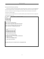
Revised January 2011
SERVICE MANUAL FOR FF 0.4 – 5 E MODELS
(Evaporator Only)
380v – 415v 3 phase 50hz
Revised January 2011
Table of Contents
I. Overview .............................................................................................................................4
II. Operation Conditions & Performance Parameters
1. Conditions for Operation ................................................................................................................ 4
2. Diagram of Ice Output of Ice Machines. ......................................................................................... 4
3. Dimensions ..................................................................................................................................... 6
4. Specifications .................................................................................................................................. 7
III. Packing, Transportation, Storage & Installation
1. Transportation and Handling .......................................................................................................... 7
2. Installation ...................................................................................................................................... 7
3. Pipe Connection Diagram ............................................................................................................. 8
IV. Operating Procedures ....................................................................................................... 9
V. Operating Principles
1. Refrigeration System .................................................................................................................... 11
2. Water Circulation System ............................................................................................................. 11
3. Ice Level Control Assembly ........................................................................................................... 12
4. The Gear Box ................................................................................................................................ 12
5. P.C. Board Control System ............................................................................................................ 12
VI. Safety Precautions .......................................................................................................... 13
VII. Cleaning Procedures .................................................................................................................... 14
VIII. Trouble-Shooting .......................................................................................................... 15
IX. Wiring Diagram............................................................................................................... 16
Wiring Diagram with Timer ............................................................................................17
X.PC Board Explained .........................................................................................................18
1. Circuit Board Layout ................................................................................................18
a) Ice making machine PC Board layout (back) ......................................................18
b) ice making external indicator small board layout ..............................................18
c) Ice full sensor sensitivity small board layout .....................................................19
Revised January 2011
2. Fault Indicator ...........................................................................................................19
3. Dip Switch ..................................................................................................................20
a) 8-bit DIP Switch ..................................................................................................20
b) 4-bit DIP Switch ..................................................................................................21
4. Electrical Wiring Diagram ..........................................................................................22
a) Ice machine PC Board wiring diagram ...............................................................22
b) Ice Machine external indicator (small board) wiring diagram ...........................22
c) Ice Making sensor wiring diagram .....................................................................23
5.Ice Full Sensor sensitivity and DIP switch settings .....................................................24
a)Full sensor sensitivity settings ............................................................................24
b) Ice Full sensor sensitivity and adjustment method ...........................................24
c) DIP Switch settings method................................................................................24
XI. Timer Switch.......................................................................................................... 25
XII. Technical Notes ..................................................................................................... 35
XIII. Service Bulletins................................................................................................... 36
Revised January 2011
I. Overview
Read this service manual carefully before installation and operation of this ice machine.
This Service Manual gives an introduction of operating conditions, performance parameters, installation
and troubleshooting procedures of the FFE series ice machine . The ice making system has a vertical, static
evaporator with a rotating auger. The machine is equipped with a P.C. board, which controls and monitors
the functionality, indicating:
(1) Ice level
(2) Water level in water tank
(3) Motor and gearbox operation
(4) Temperature of Evaporator
II. Operation Conditions & Performance Parameters
1. Conditions for Operation
Ambient Temperature
Water Temperature
Water Pressure
Deviation from Voltage Rating
Minimum
Conditions
Operating
Maximum Operating Conditions
5°
5°
40°
40°
0.15MPa
-10%
0.5MPa
+10%
4
Revised January 2011
2. Diagram for Ice Output of Ice Machine
FF0.4E
FF0.6E
FF1.2E
FF1.5E
FF2.5E
FF3.2E
The parameters are subject to change without notice.
5
FF1 E
FF2 E
Revised January 2011
3. Dimensions (see figure 1)
Pipe Connection (Front View)
Standard
Ice Output
Type
1000kg
/24h
Dimension
mm
(L×W×H)
Gear
Box
Motor
Power
(W)
Pipe Connection (Top View)
Water
Water
Inflow
Water
Water
Air
Inlet
Pump
Refrigeratio Tube
Weight
over
Suction
Consum
Pipe
Motor
(t)
n Power
OD
flow
ption
Tube OD
(female
Power
Ф(mm
kg
(kW)
Pipe
l/h
Ф(mm)
threade
(W)
)
(OD)
d)
10
17
2.2
20
25
170
¾”
Ф21
FF0.4E
0.4
1090*700*720
120
FF0.6E
0.6
1250*750*820
120
10
25
3.3
20
30
160
1
1050*850*870
180
10
42
5.5
12.7
22
FF1.2E
1.2
1050*850*880
180
10
50
6.6
12.7
FF1.5E
1.5
1050*850*1050
180
10
63
8.5
2
1050*850*1080
180
20
83
FF2.4E
2.4
1050*850*1250
180
20
FF3.2E
3
1050*850*1300
180
FF5E
5
1850*1150*1250
370
FF1E
FF2E
Ф21
170
¾”
¾”
22
180
¾”
Ф21
12.7
28
200
Ф21
11.0
12.7
28
230
¾”
¾”
100
13.5
12.7
28
240
¾”
Ф21
20
125
16.5
12.7
28
280
¾”
Ф21
65
208
28.0
28
54
800
1”
2*Ф21
Ф21
Ф21
4. Specifications
Notes:
1. Standard operating conditions: Ambient temperature 25° air and water temperature 16°.
2. The evaporator temperature shall be -22° and condenser temperature + 45° (air-cooled) or
40° (water-cooled).
An EPR valve is recommended with multi compressor/ evaporator systems.
3. Power supply: 415V/50HZ/3N
4. Refrigerant: R404A
5. Supply water pressure: 0.15-0.5MPa
6
Revised January 2011
III. Packing/ Transportation/ Storing and Installation
1. Packing, Transportation and Storing The ice machine is packed in plywood.
Beware of collision, vibration, tilting, inversion, etc. in transportation and storage. Ice machine should
be kept below 40C, dry, and well-ventilated
Before you begin:
A. Check your paperwork to determine the model received matches your order.
B. After uncrating and removing all packing material, inspect equipment for any shipping damage.
C. Check whether all connections (water system, refrigerant system, etc.), electrical connections (wires,
PC board, etc.) and mechanical system are in good condition.
2. Installation
A. Electrical connections must comply with local standards and requirements on the rating plate of the
machine.
B. An isolation switch must be installed
C. Constant water supply (Pressure between 0.15 kPa to 0.5 MPa) and stop cock shall be supplied within
1 mtr of the ice machine. Suitable drainage point shall be within 1 mtr of ice machine. Two separate
water drainage lines shall be required for draining the ice machine and the ice storage bin.
D. The ice machine shall not be placed (1) without suitable ventilation; (2) next to heat sources; or (3)
outdoors.
E. To ensure ice quality a water filter should be installed in icemaker inlet water line.
7
Revised January 2011
3. Pipe connection Diagram and Machine dimensions and Ice Outlet Dimensions
Pipe
connection
Pipe
(Front
connection
(Top
Dimension of ice outlet
Refrigeran
D
t
Mounting
Hole
Refrigeran
t
W
Figure 3
Type
A
B
C
D
E
D
W
H
Φ
FF0.4E
87
395
658
447
216
1050
850
870
326
FF0.6E
95
450
665
430
419
1250
750
820
326
FF1E
150
750
198
490
310
1050
850
870
480
FF1.2E
150
750
198
490
310
1050
850
880
480
FF1.5E
150
750
198
490
310
1050
850
1050
480
FF2E
150
750
198
490
310
1050
850
1080
480
FF2.4E
150
750
198
490
310
1050
850
1250
480
FF3.2E
150
750
198
490
310
1050
850
1300
480
8
Revised January 2011
IV. Operating Procedures
1. Before start up check the following:
1) Power connections are safe, reliable and complies with local standards and requirements on the rating
plate on the machine
2) Water pressure is within the specified range of 0.15-0.5MPa.
3) The earth wire is securely connected.
4) All fastening bolts have been tightened.
2. Start
1) Open water supply valve to fill up the water tank, the float valve will automatically close when water
reaches the desired level.
2) During testing turn on the circuit breaker, Turn Manual “Off/Auto” button on the electrical cabinet to
Start position, enabling the ice-maker to enter a 5-minute-delay state (Start Delay indicator light blinks)
which is followed by the automatic start of gear box and water pump (1) Check that the ice blade is
rotating in the right direction (2) water level in distributor pan is aligned with the red mark and water
flow is adequate. If operation is normal then switch Stop / Start switch to Stop.
3) Ice production stage: Switch the Start/Stop button of ice machine to Start, which enables the ice
machine to start ice production after a 5-minute delay. Start refrigeration system and open suction and
liquid line valves. When refrigeration system reaches an evaporator temperature of -20c, Ice will be
produced.
3. Stop
When the Manual “Off/Auto” button is switched off, water pump and liquid line solenoid valve stop
working immediately, and the gear box stops working after a 3-minute delay so as to remove ice left on
the interior of the evaporator cylinder.
4. Failure due to alarm
1) Unit stopped due to ice full level alarm (normal stop):
When PC board detects full level of ice in storage bin, Water pump and solenoid valve are stopped first,
and then the gear box motor stops after a 3-minute delay and ice full level indicator turns on at the
same time. Now the system is in stand-by mode. After the ice is removed from bin full sensor, the
system will return to normal operating status: gear box motor, water pump and solenoid valve will be
started in sequence.
2) Failure due to low water level alarm:
When PC board detects low water level in the storage tank: water pump and solenoid valves stop first,
and then gear box motor stops after a 1-minute delay and low water level indicator turns on at the
same time. Now the system is in stand-by mode. After the water tank is refilled, the system
automatically returns to normal operating status: gear box motor, water pump and solenoid valve will
be started in sequence.
3) Failure due to low speed of gear box motor (Fault Light ON)
When PC board sensor detects suspension, reversal or low speed of gear box motor, Gear box motor,
water pump and solenoid valve stop and give alarms simultaneously. Fault will need to be diagnosed,
eliminated and PC fault reset for system to return to service.
9
Revised January 2011
4) High evaporator temperature alarm (Fault Light FLASHING)
After 10-minutes of operation, PC board begins temperature detection program: when evaporator
temperature exceeds a set point, the microprocessor implements a Hi-temp fault program: water pump
and solenoid valve stop immediately and gear box stops after a 6-minute delay and gives alarm signal
simultaneously. The fault will need to be diagnosed, rectified and fault reset for system to return to
service.
Other notes: This machine does not indicate condenser temp.
A. Electric box Panel Diagram 5:
Manual Off/Auto switch
install on ITS
Figure 5
B. Manual “Off/Auto” Switch
a. Starts or Stops the machine.
b. Restarts the machine after a fault has been rectified.
C. “DIP” Switch: P.C. board is equipped with 8“DIP” switches, which do not need to be adjusted in normal
operation, all switches are set to OFF position except No.2, No.3 and No.6 switch to ON position, as
shown in Figure 6 below.
DIP
ON
OFF
Figure 6
No.1 Switch: When the switch is set to ON position, the machine will be started without a 5-minute delay;
when it is set to OFF position, the machine will be started with a 5-minute delay. The switch is set to OFF
position at factory.No.2 & No.3 switches: are in ON position for sub zero ice production.
No.6 switch: Alarm buzzer, factory set in On position.
10
Revised January 2011
V. Operating Principles
1. Refrigeration System(See Figure7)
When liquid refrigerant flows through evaporator cylinder, the refrigerant lowers the temperature of
the evaporator cylinder through heat exchange, meanwhile water in contact with the evaporator
surface freezes, and ice detaches from the surface from the action of the ice blade rotation and falls
into ice storage bin.
2. Water Circulation System(See Figure7)
Supply water flows into the water tank via the float valve. Water is pumped into the distributor pan
and then flows to the evaporator’s interior surface. The cooling process occurs gradually and part of
the water turns into ice. The ice is detached from the interior by the rotating blade and falls into the
ice storage bin.
Note:
1) Feed water level is monitored by a sensor. In case water tank runs out of water or has soft water
(demineralized), P.C. board stops the operation of the machine and the yellow LED turns on to indicate
low water level alarm. The machine will reset to normal operation after water level recovers.
2) When being tested at the factory, the water level in water distributor pan has been set in line with the
red mark on the water level indicating bolt, If the water level is not in line with the red mark, the
specified water level can be achieved through adjusting the valve in water tank or the valve fixed on
the top of evaporator(with the depth of water in the pan being 26mm for 10-ton and smaller ice
machine, 38mm for 15-ton and bigger ice machine).
Gear motor
Gearbox
Water Tray
H (Water Level)
Ice blade
Suction line
Water pump
Main shaft
Water tank
Evaporator
Liquid line
Water inlet
Drip pan
Lower strut
Figure 7
11
Revised January 2011
3. Ice Level Control.
Between ice machine and ice storage tank there is an optical ice level control sensor. When the ice
reaches the sensor and blocks the optical beam, the red LED at the center of the P.C. board goes out
immediately. After the light beam has been blocked for a given time, production of ice stops and the
yellow LED turns on to indicate ice full state. When ice is removed from the sensor, the light beam
resumes and the red LED on the P.C. board lights immediately. Ice machine restarts in 10 seconds and
ice full, yellow LED goes out.
4. Gear box system
This system consists of gearbox motor and gearbox. The former drives the latter, and the gearbox
output shaft propels the rotating ice blade and water distributor pan. When gearbox motor runs in the
wrong direction or its speed is less than 1300rpm, a signal is sent by the sensor to the P.C. board, which
stops the operation of ice machine. The cause of fault must be identified and the fault eliminated
before ice machine will restart. Press the Reset button on the P.C. board once or turn the Start/Stop
button to reset the unit.
5. P.C. Board Control System (See Figure 8)
THE P.C. Board controls the entire process of ice machine operation based on the signals transmitted by
different sensors.
Water level
Detection electrode
Water level judgment
circuit 1
Ice level sensor
Ice level judgment
Circuit 2
Motor operation
Sensor
Motor rotation
signal circuit 3
Evaporation temperature
Sensor
P/C
Evaporation temperature
t circuit 4
High-temperature protection
circuit 5
Condensation temperature
Sensor
Not used on FFE
Compressor controlling
circuit 9
Ice level sensor
state indication
Low-temperature Protection
circuit
Fan on-off judgment
Circuit 7
Gear motor controlling
circuit 10
Fan controlling
circuit 11
Figure 8
12
Compressor
Contactor
Gear motor
Fan motor
Revised January 2011
VI. Safety Precautions:
Warning: Main power supply must be cut before conducting any operation for cleaning and
maintenance,Especially when the ice-machine is in the “bin full” and “no water” states. In this case, DO
NOT do any maintenance or repair of the ice-machine (especially the inner part of the machine),
Ice-machine may automatically start at any time.
Special care for the following safety precautions shall be taken into account
during commissioning, normal operation and maintenance of ice machine.
1) No repair or maintenance shall be carried out before ice machine has been confirmed not in operation
and disconnected from main power supply.
2) With ice machine in operation or energized, no body part or other object shall be allowed to enter the
evaporator barrel.
3) After a power loss or outage, Take care to check rotation of gearbox
4) During installation, commissioning and operation be sure not to allow body to contact discharge pipes.
5) All refrigerant pipe work needs to be inspected and fully pressure tested before commissioning.
6) All state and local guide lines and standards must be adhered to.
13
Revised January 2011
VII. Cleaning Procedures
Warning:
No cleaning or maintenance shall be carried out on the machine prior,
to carrying out correct isolation procedures to isolate the machine
from the power and water supply. Coast Distributors recommends the
use of PPE when carrying out a service or maintenance on either the
ITS, BIN, or Grant ice machine.
1. Carry out correct isolation procedures and test unit for power loss.
2. Isolate the water supply to the machine.
3. Remove and replace the water filter cartridge and purge approx 4ltrs of water through
filter.
4. Carry out visual inspection of the unit.
5. Remove the black top plastic cover on the evaporator.
6. Check condition of water distributor and tubes.
7. Check condition of plastic water pan at the bottom of evaporator.
8. Check water float operation and water level. Adjust or replace if required.
9. Check water trough for foreign matter and clear if required.
10. Check water reservoir.
11. Check for any water leaks.
12. Isolate the refrigeration circuit, so as no refrigeration of the evaporator occurs this can
be done by either separating the compressor overload from the contactor ( all AR
models )or isolating the power to the liquid line solenoid valve coil on (all FFE models)
13. Drain the water from the water reservoir via the drain tap on rear of tank and measure
water quantity. This is to ascertain how much cleaning solution is required.
14. Make up correct amount of cleaning solution as per manufacturer’s directions and
empty solution into the water reservoir.
15. Re-energize the power to the machine and set dip switch 1of 8 (time delay override)
to the up position and turn the machine on.
16. Run the machine for the correct indicated time as per chemical manufactures
directions (usually 20 min). During this time the machine will fault on high evaporator
temp alarm (10 min delay) and will require a reset to start the alarm delay over again.
17. Once the cleaning time has elapsed, turn unit off and drain the water and flush the
system 4 times.
18. Clean the bin and flush / check the drain.
19. Drain the water from the water reservoir via rear drain tap.
20. Mix up and add sanitizer solution to the system, turn unit back on.
21. Sanitize bin.
22. Follow the manufactures directions on the sanitization procedure.
23. After 10 min reset and wait another 10 min. Once this time has elapsed, turn the unit
off and drain the water and flush the system 4 times.
24. Carry out correct isolation procedure and test unit for power loss.
25. Re-connect the compressor overload or solenoid valve coil power.
26. Reset the delay timer dip switch (no 1 of 8) back to the off position “Down”.
27. Clean the unit, condenser and covers where fitted.
28. Turn the water back on to the machine.
29. Re-energize the power and turn the machine on.
30. Check operation of unit.
31. Check Auto/Off/Man operation and time clock setting.
32. Check bin legs, door and trolleys where applicable.
The above procedure takes approx 1.5 to 2 hrs depending on, if is on a slope front bin or a
Follett ITS.
14
Revised January 2011
VIII. Trouble-shooting
Fault Description
Possible Causes
Recommendations
Machine inactive
(1) PC board Power indicator not
on
Main switch is set to OFF position
P.C. board’s fuse blown (750mA)
Malfunction of P.C board
Selector switch needs to be set to
ON position
Replace the fuse and diagnose the
cause of fuse fault
Replace the P.C.Board
(2) Ice full level indicator on
Connection wire loose
Malfunction of ice level control assy.
(3) Low water level indicator on
Low water level or water too soft
(4) Evaporator temp indicator
( flashing )
Evaporator temp. sensor damaged
Low gas charge
High ambient temp
Replace
Check/ leak test and repair
(5) Low rotation speed indicator
( on )
Gear box motor’s rotation reversed
Check motor wiring and capacitor/
phase rotation
Compressor runs intermittently
Low ice production
Ice machine in operation but no
ice is being produced
Water leak
Noisy gearbox
Low water level
Gear box motor’s spinning speed is too
low
Check the wiring
Clean or replace ice level control
assembly
Please refer to recommendations for
low water level alarm
Check motor bearing, evaporator
cylinder bearings, TX adjustment
Voltage is too low
Non condensables
Loose compressor contact terminals
Expansion valve partially blocked or
not adjusted properly
Moisture in the system
Low water level in distributor pan
Low refrigerant charge
No water in water cylinder for ice
production
Gear box not rotating
Water level is too high in water tank
Water level is too high in distributor
pan
Motor’s bearings worn out
Gear box low in lubrication oil
Gear box’s bearing and gears worn
Check supply power and wiring
Eliminate the fault
Check and tighten all wiring
Adjust TX valve
Feed water pipe blocked
Dismantle and clean the pipe
15
Reclaim gas, evacuate and charge
Adjust it to the specified water level
Check for leaks and charge
Check water pump , flow valve and
pipe work
Check, repair or replace it
Adjust
Adjust
Check or replace it
Check gear box and add lube oil
Check and replace the worn parts
Revised January 2011
X.Wiring Diagram
Gear box motor sensor
Vaporizer temperature sensor
Condenser temperature sensor
Ice level sensor
Water level sensor
16
16
16
RD3
RD2
RD1
YA
M2
M1
KT
XJ
H1
H2
H3
H4
H5
H6
H7
RJ1
KM2
KM1
K2
QF
Fuse for power supply indicator
Fuse for solenoid valve power
Fuse for water pump power
Solenoid valve
Water pump
Speed reducer
Delay contactor
Protector for phase breaking
P.C. board power supply indicator
Ice full indicator
water shortage indicator
Hi condensation temperature/start delay indicator
Low speed/high vaporization temperature indicator
Breaking phase malfunction indicator lamp
Power supply indicator
Thermal overload protector for speed reducer
AC contactor of water pump
AC contactor of speed reducer
P.C. board switch
Air switch
Notes: This machine does not use condenser temperature sensor
Revised January 2011
17
Revised January 2011
X. PC BOARD EXPLAINED
1、Ice making PC board layout (back)
b) Ice making external indicator small board layout
18
Revised January 2011
c) Ice full sensor sensitivity small board layout
2. Fault Indicator
* When the power frequency is lower than 45Hz more than five seconds all the indicator lights flash at
the same time
19
Revised January 2011
3. Dip Switch
1. 8-bit DIP switch (Attention: Please press reset button before resetting DIP switch.)
Cancel the buzzer (off)
Start up delay function on
Open the buzzer (on)
Cancel start up delay
function
Select 1440RPM model
Cancel the test
parameters (factory)
Select sub zero ice machines
ice full sensor
Open the test
parameters (factory)
Eight-bit DIP switches on the centre of the PC board (Figure 3-1) are from left to right. Override is when
dip switch is in the on position.
The function of the first bit DIP switch: Selects the starting up delay function. When the first bit DIP switch
is on, the unit will start up with no delay. (This feature is used during maintenance of the ice machine).
When dip switch is in the off position the unit will have a five minute delay, which is to ensure the sensor
is clear of ice.
The function of the second and third bit DIP switch: Select the ice full sensor to suit ice type. To select sub
zero machine ice-full sensor, both dip switch`s 2 and 3 are in the on position.
.
The function of the fourth bit DIP switch: DIP switch invalid.
The function of the fifth bit DIP switch: Selects the models of the gear motor.
1440 RPM when the dip switch is in the off position ( the location of switch has been set up at the factory,
the user should not be touched)
The function of the sixth bit DIP switch: Selects the buzzer alarm. When the sixth bit DIP switch is in the
on position, the buzzer will alarm when a fault is triggered, in contrast, the buzzer is silent when the dip
switch is in the off position.
The function of the seventh bit DIP switch: DIP switch is invalid.
The function of the eighth bit DIP switch: Selects the test parameters .(testing the PC board design
parameters at factory).( the switch has been set off at the factory)
20
Revised January 2011
b) 4-bit DIP switch (Warning: Please press reset button before resetting DIP switch.)
Turns on the low-rotating speed fault
protection
Turns on the evaporating temperature
protection
Cancels the low-rotating speed fault
protection
Cancels the evaporator temperature
protection
Turns on the condensing temperature
protection
Turns on the ice full protection
Cancels the condensing temperature
protection
Cancels the ice full protection
Four-bit DIP switches on the center of the PC board (Figure 3-2) are in order from left to right.
The function off the 4 dip switch’s are to bypass any of the 4 sensors so the machine can continue to
function until the fault is rectified. When a bypass is activated the fault light for that sensor will continue
to be activated until the fault is rectified and the unit is reset.
21
Revised January 2011
4.Electrical wiring diagram
a). Ice machine PC board wiring diagram
Ice making PC board layout (front) figure 4-1
22
Revised January 2011
Power Indicator
Ice full fault indicator
Water shortage fault indicator
Condenser fault indicator / delay indicator
Rotating speed fault indicator / evaporator
Fault Indicator
b) Ice machine external indicator (small board) wiring diagram
c) Ice making sensor wiring diagram
5.Ice full sensor sensitivity and DIP switch settings
a)、Ice full sensor sensitivity settings
Flake ice machine:XB70—XB550 model
5 indicator.
Sub Zero machine:PB0.4F/A—PB50F/A model
5 indicator.
23
Revised January 2011
b) setup of ice full sensor sensitivity
Ice full sensor sensitivity may diminish after a certain period of time. At this time, It can be adjusted by
the ice full sensitivity resistor on the PC board. Clockwise rotation will increase the number of lights; ice
full sensor sensitivity will increase accordingly. Anti clockwise rotation will decrease sensitivity and
decrease the number of lights
The LED 1 next to the 8 dip switches is the sensitivity indicator, when the LED is lit the bin is empty, when
the LED is off the bin is full.
3、DIP switch setting methods table
1(ON): Cancel ice full protection.
2(ON): Cancel evaporation temperature protection.
3(ON): Cancel condensing temperature protection.
4(ON): Cancel low rotating speed protection.
1 (ON): Cancel starting up delay.
2,3 (ON):Select sub zero ice machine’s ice-full sensor
4 (OFF): Not Used
5 (OFF): Select 1440RPM model.
6 (ON): Turn on the buzzer.
Warning: Please press reset button before resetting DIP switch
24
Revised January 2011
Grant Timer with remote switch
The Grant unit can be fitted with a remote switch and timer, the function of this is twofold.
As the electrical control board is placed on the unit, this can make access to the factory fitted switches difficult.
The remote switch allows the ON/OFF/AUTO switch to be placed in an easily accessible location, such as when
the unit is placed on a large ice bin or transport system i.e. Follet ITS or DEV.
The timer is designed to reduce the ice clumping found with storing scale type ice for long periods. The theory
is to supply only the ice needed for the demand, an example would be:
Grant one ton FFE on a Follett DEV. (ice bin)
Customer requires 400 kg of ice at 7am and 200kg at 4pm.
Timer will require to be set from 10pm to 7am and 11am to 4pm
Grant 1 ton FFE = 1000kg/24hrs = 41kg/1hr
400kg will require the unit to run for 10hours.
200kg will require the unit to run for 5hours.
Of course this is only an example and every application will vary but the principal is the same, it will be up to
the technician to consult with the customer and set timer to suit their needs.
With the timer set up correctly, the machine will produce Ice on demand and prevent clumping of ice in the
storage bin.
a) Parts Identification
25
Revised January 2011
b) Operating Instructions
Before turning power ON, Check that your unit conforms to the operating voltage.
If the unit has not been in operation for a long period the battery may have discharged and may not work
immediately. Connect the unit and switch power source on, wait for approximately ten minutes before
setting the timer. Full power reserve is built up after approximately 72 hours.
1. Setting the timer
Set the setting pin between the desired times to the left or right of the dial.
Set the setting pin to the right of the dial; ON position
If the setting pin is set to the ON position continuously, it will continue only for the number of setting pins x
15 minutes.
Set the setting pin to the right until a click is heard
Set the setting pin to the left of the dial; OFF position
2. Adjust the present time
Turn the dial until the index is on the current time
3. Set the manual switch:
Use this switch to select either ON or OFF in manual or ON/OFF in the operation program.
“Auto”; output is turned ON and OFF according to the set program
Manual “ON”; output is turned ON irrespective of the program (Use this mode for
test operation)
Manual “OFF”; output is turned OFF irrespective of the program.
After completing test operation set the manual switch to “AUTO”
26
Revised January 2011
c) Specifications
Rated Voltage
240VAC
Voltage tolerance
220-260VAC
Frequency
50hz
Power consumption
1w
Drive Method
Quartz controlled stepping motor
Cycle
24 hours
Time precision
+/-3 sec/ day at 22 degrees Celcius
Circuit
Separate
Switch construction
SPST
Manual ON/OFF
ON/AUTO/OFF switch
Load
Capacity
Resistive Load
16A
Incandescant lamp
10A
Inductive
12A
Motor
220v AC 1500W
Present Time Setting
Setting
Turn dial until the index is at the current time
ON/OFF program setting
15 minutes
Minimum Unit
15 minutes
Minimum interval
15 minutes
No of ON/OFF operation
96 operations
Working reserve time
72 hours
Ambient temperature
-10 degrees celcius ~ +50 degrees celcius
Ambient humidity
Max 85%
Weight
85g
27
Revised January 2011
XII . Technical Notes
1. All PC boards after November 2009 will be the bypass model which will allow all sensors to be bypassed for
diagnostic purposes.
2. All Grant ice machines up to 10 ton use the same PC board.
3. All grant ice machines 10 ton and over use a PLC.
4. All the old style PC boards have no bypass on any faults except by bridging using the correct ohm resister.
5. Bin full sensor can be bypassed by bridging terminals 2 and 3.
6. All sensors can be bypassed with the correct resister.
7. Low temp sensor can be bypassed with a 10 ohm resister.
8. High condenser temp sensor can be bypassed with a 91 ohm resister.
9. Gear motor speed sensor cannot be bypassed.
10. The square blue potentiometer on the PC board is to set/adjust the sensitivity of the bin full sensor. A
correct setting is 5 lights on the small circuit card on the front of the board. If the sensitivity is set to high the
sensor can burn out.
11. Speed sensor operates at 1440rpm with a 7% differential.
12. Speed of the gearbox is governed by the hertz and should be checked on every installation.
13. Hertz under 45 will cause low rotation fault.
14. Phase fail control requires a voltage of not less than 380 or greater than 450 volts, but can be set at 10%
lower to get out of trouble but is not recommended.
15. Scraper must always be set at 0.3mm off evaporator shell, use a set of feeler gauges.
16. Incorrect ice thickness will trip speed sensor and cause shuddering.
17. If gearbox / scrapper shuddering occur water flow is too great and should be reduced and or TX valve may
need adjusting.
18. TX feed can be checked by ice formation on evaporator, i.e. ice forming lines in evaporator increase TX feed.
19. The core dryer fitted to the suction line has no core fitted; the dryer is there for quality control at the
factory and is removed after testing.
28
Revised January 2011
XIII. Service Bulletins
Coast tip of the week:
Blocked water filter bypass
If you need to bypass the water filter in an emergency you can carry out the following to get
you out of trouble until you can replace the cartridge.
1.
2.
3.
4.
5.
Isolate water to filter
Remove filter cartridge
Remove small O ring
Re-install filter cartridge
Turn water back on
By caring out the above, this bypasses the cartridge and allows water to flow to your
machine.
NOTE: return and replace the filter cartridge as soon as possible
29
Revised January 2011
Water regulating valve
If there is water dripping or flowing into the bin from under the evaporator,
check the water flow over the evaporator.
Ball float adjustment under
Water flow regulator valve
To adjust the water flow so as not to overflow the drain catchment tray, adjust
this valve slowly to regulate the water flow. If the flow is too high, the water
overflows the drain tray. If the flow is insufficient there will be little ice
production.
30
Revised January 2011
31
Revised January 2011
1800 688 590
Ph: 02 9524 1234
Fax: 02 9524 0968
Email: [email protected]
Web: www.coastdistributors.com.au
32