1
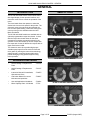
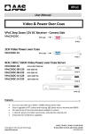
SERVICE MANUAL
Legacy TM
HL300
ML-134351
HL300C
ML-134358
HL400
ML-134348
HL400C
ML-134359
- NOTICE This Manual is prepared for the use of trained Hobart Service
Technicians and should not be used by those not properly
qualified. If you have attended a Hobart Service School for this
product, you may be qualified to perform all the procedures
described in this manual.
This manual is not intended to be all encompassing. If you have not
attended a Hobart Service School for this product, you should read,
in its entirety, the repair procedure you wish to perform to
determine if you have the necessary tools, instruments and skills
required to perform the procedure. Procedures for which you do
not have the necessary tools, instruments and skills should be
performed by a trained Hobart Service Technician.
Reproduction or other use of this Manual, without the express
written consent of Hobart, is prohibited.
A product of HOBART
Troy, Ohio 45374
F25250 (August 2007)
HL300 AND HL400 LEGACY MIXERS
TABLE OF CONTENTS
GENERAL . . . . . . . . . . . . . . . . . . . . . . . . . . . . . . . . . . . . . . . . . . . . . . . . . . . . . . . . . . . . . . . . . . . . . . . . . . . . . . . .
Introduction . . . . . . . . . . . . . . . . . . . . . . . . . . . . . . . . . . . . . . . . . . . . . . . . . . . . . . . . . . . . . . . . . . . . . . . . . . . .
Reference Material . . . . . . . . . . . . . . . . . . . . . . . . . . . . . . . . . . . . . . . . . . . . . . . . . . . . . . . . . . . . . . . . . . . . . .
Timer Options . . . . . . . . . . . . . . . . . . . . . . . . . . . . . . . . . . . . . . . . . . . . . . . . . . . . . . . . . . . . . . . . . . . . . . . . . .
Specifications . . . . . . . . . . . . . . . . . . . . . . . . . . . . . . . . . . . . . . . . . . . . . . . . . . . . . . . . . . . . . . . . . . . . . . . . . .
Lubrication . . . . . . . . . . . . . . . . . . . . . . . . . . . . . . . . . . . . . . . . . . . . . . . . . . . . . . . . . . . . . . . . . . . . . . . . . . . .
Tools . . . . . . . . . . . . . . . . . . . . . . . . . . . . . . . . . . . . . . . . . . . . . . . . . . . . . . . . . . . . . . . . . . . . . . . . . . . . . . . . .
3
3
3
3
4
5
5
COVERS . . . . . . . . . . . . . . . . . . . . . . . . . . . . . . . . . . . . . . . . . . . . . . . . . . . . . . . . . . . . . . . . . . . . . . . . . . . . . . . . . 6
BOWL GUARD ASSEMBLY . . . . . . . . . . . . . . . . . . . . . . . . . . . . . . . . . . . . . . . . . . . . . . . . . . . . . . . . . . . . . . . . . . 7
BOWL SWITCH . . . . . . . . . . . . . . . . . . . . . . . . . . . . . . . . . . . . . . . . . . . . . . . . . . . . . . . . . . . . . . . . . . . . . . . . . . . . 9
TIMER BOARD . . . . . . . . . . . . . . . . . . . . . . . . . . . . . . . . . . . . . . . . . . . . . . . . . . . . . . . . . . . . . . . . . . . . . . . . . . . 10
SPEED SELECTOR SWITCH . . . . . . . . . . . . . . . . . . . . . . . . . . . . . . . . . . . . . . . . . . . . . . . . . . . . . . . . . . . . . . . . 11
MOTOR DRIVE . . . . . . . . . . . . . . . . . . . . . . . . . . . . . . . . . . . . . . . . . . . . . . . . . . . . . . . . . . . . . . . . . . . . . . . . . . . 13
MOTOR . . . . . . . . . . . . . . . . . . . . . . . . . . . . . . . . . . . . . . . . . . . . . . . . . . . . . . . . . . . . . . . . . . . . . . . . . . . . . . . . . 15
PLANETARY . . . . . . . . . . . . . . . . . . . . . . . . . . . . . . . . . . . . . . . . . . . . . . . . . . . . . . . . . . . . . . . . . . . . . . . . . . . . . 17
TRANSMISSION / ATTACHMENT HUB . . . . . . . . . . . . . . . . . . . . . . . . . . . . . . . . . . . . . . . . . . . . . . . . . . . . . . . . 19
WRAP . . . . . . . . . . . . . . . . . . . . . . . . . . . . . . . . . . . . . . . . . . . . . . . . . . . . . . . . . . . . . . . . . . . . . . . . . . . . . . . . . . . 26
TRANSMISSION CASE . . . . . . . . . . . . . . . . . . . . . . . . . . . . . . . . . . . . . . . . . . . . . . . . . . . . . . . . . . . . . . . . . . . . . 27
BASE . . . . . . . . . . . . . . . . . . . . . . . . . . . . . . . . . . . . . . . . . . . . . . . . . . . . . . . . . . . . . . . . . . . . . . . . . . . . . . . . . . . 28
BOWL SUPPORT . . . . . . . . . . . . . . . . . . . . . . . . . . . . . . . . . . . . . . . . . . . . . . . . . . . . . . . . . . . . . . . . . . . . . . . . . 29
BOWL LIFT ASSEMBLY . . . . . . . . . . . . . . . . . . . . . . . . . . . . . . . . . . . . . . . . . . . . . . . . . . . . . . . . . . . . . . . . . . . . 30
BOWL TO BEATER CLEARANCE ADJUSTMENT . . . . . . . . . . . . . . . . . . . . . . . . . . . . . . . . . . . . . . . . . . . . . . . . 31
ELECTRICAL OPERATION . . . . . . . . . . . . . . . . . . . . . . . . . . . . . . . . . . . . . . . . . . . . . . . . . . . . . . . . . . . . . . . . . .
Component Function . . . . . . . . . . . . . . . . . . . . . . . . . . . . . . . . . . . . . . . . . . . . . . . . . . . . . . . . . . . . . . . . . . .
Component Location . . . . . . . . . . . . . . . . . . . . . . . . . . . . . . . . . . . . . . . . . . . . . . . . . . . . . . . . . . . . . . . . . . .
Motor Drive Layout . . . . . . . . . . . . . . . . . . . . . . . . . . . . . . . . . . . . . . . . . . . . . . . . . . . . . . . . . . . . . . . . . . . . .
Sequence of Operation . . . . . . . . . . . . . . . . . . . . . . . . . . . . . . . . . . . . . . . . . . . . . . . . . . . . . . . . . . . . . . . . . .
Schematic Diagrams . . . . . . . . . . . . . . . . . . . . . . . . . . . . . . . . . . . . . . . . . . . . . . . . . . . . . . . . . . . . . . . . . . .
Wiring Diagrams . . . . . . . . . . . . . . . . . . . . . . . . . . . . . . . . . . . . . . . . . . . . . . . . . . . . . . . . . . . . . . . . . . . . . . .
32
32
33
34
38
40
44
TROUBLESHOOTING . . . . . . . . . . . . . . . . . . . . . . . . . . . . . . . . . . . . . . . . . . . . . . . . . . . . . . . . . . . . . . . . . . . . . .
Quick Reference Flow Chart . . . . . . . . . . . . . . . . . . . . . . . . . . . . . . . . . . . . . . . . . . . . . . . . . . . . . . . . . . . . .
General - All Models . . . . . . . . . . . . . . . . . . . . . . . . . . . . . . . . . . . . . . . . . . . . . . . . . . . . . . . . . . . . . . . . . . . .
Alarm Codes . . . . . . . . . . . . . . . . . . . . . . . . . . . . . . . . . . . . . . . . . . . . . . . . . . . . . . . . . . . . . . . . . . . . . . . . .
46
46
47
49
INDEX . . . . . . . . . . . . . . . . . . . . . . . . . . . . . . . . . . . . . . . . . . . . . . . . . . . . . . . . . . . . . . . . . . . . . . . . . . . . . . . . . . 52
© HOBART 2007
F25250 (August 2007)
Page 2 of 52
HL300 AND HL400 LEGACY MIXERS - GENERAL
GENERAL
INTRODUCTION
TIMER OPTIONS
The HL300 and HL400 mixers utilize a timer board
with digital display for the operator interface; and
electronic motor drive to control the operation of the
mixer.
The timer board allows the operator to select the
desired mix time and mix speed for the product. The
electronic motor drive stores the last selected mix
time for each speed setting. Continuous mixing with
count up timing is also available when the Hold
Mode is selected.
The HL300 and HL400 models are available with an
optional programmable recipe timer board. A mixer
with the recipe timer board allows for the same
operation but includes programing options for the
operator to store and retrieve up to four recipes with
five steps each for the HL300 and six recipes with six
steps each for the HL400.
The electronic motor drive provides high torque
variable speed output from the motor to fixed ratio
drive gears. By utilizing the motor drive technology,
agitator speed is controlled electronically which
permits changing mixing speeds anytime during
mixer operation.
REFERENCE MATERIAL
•
HL300 Catalog of Replacement
Parts
- F43136
•
HL400 Catalog of Replacement
Parts
- F43137
•
Instruction Manual for Installation,
Operation and Care
- F34975
•
Lubrication Manual for current
lubricants and quantities
- F20067
•
Use and Applications Handbook
- F34901
•
Mixer Capacity Chart - All Models
- F7701
HL300 STANDARD TIMER BOARD
HL300 RECIPE TIMER BOARD
HL400 STANDARD TIMER BOARD
HL400 RECIPE TIMER BOARD
Page 3 of 52
F25250 (August 2007)
HL300 AND HL400 LEGACY MIXERS - GENERAL
SPECIFICATIONS
HL300 ELECTRICAL DATA
200-240/50/60/1
200-240/50/60/3
5.7
2.8
0.75 H.P.
0.75 H.P.
2.5HP,
2.5HP
Voltage*
Amps
Mixer
100-120/50/60/1
9.5
0.75 H.P.
2.5HP,
380-460/50/60/3
1.4
0.75 H.P.
2.5HP,
Motor
230/460V,
230/460V,
230/460V,
230/460V,
3 phase
3 phase
3 phase
3 phase
*Tolerance +/- 10%
HL400 ELECTRICAL DATA
Voltage*
200-240/50/60/1
200-240/50/60/3
380-460/50/60/3
Amps
9.3
5.6
2.4
Mixer
1.5 H.P.
1.5 H.P.
1.5 H.P.
3.0HP.
3.0HP.
3.0HP.
208-230/460V,
208-230/460V,
208-230/460V,
3 Phase
3 Phase
3 Phase
Motor
*Tolerance +/- 10%
OPERATING SPEEDS AND RPM
Model Speed
HL300
HL400
Planetary
Beater
Attachment
STIR
25
58
34
1
41
94
55
2
77
174
101
3
140
317
185
STIR
25
58
34
1
41
94
55
2
77
174
101
3
140
317
185
BOWL SIZE
F25250 (August 2007)
HL300
30 qt. bowl
HL400
40 qt. bowl
Page 4 of 52
HL300 AND HL400 LEGACY MIXERS - GENERAL
MIXER TORQUE VALUES
Component
Torque
Base to Pedestal
900-1100 in*lb
Transmission Case to
372-465 in*lb
Pedestal
Slideways to Pedestal
175-275 in*lbs
Internal Gear to
175-275 in*lbs
Transmission Case
Transmission Cover Bolts
175-275 in*lbs
Motor to Transmission Case 24-30 in*lbs
Bottom Planetary Screw
372-465 in*lbs
TOOLS
Standard
LUBRICATION
Lubrication
Standard set of hand tools.
•
Digital Multi-meter (DMM) with sensitivity of at
least 20,000 ohms per volt.
•
Clamp-on ammeter
Special
MOTOR DRIVE TORQUE VALUES
Screw
Location
Torque
Size
Main Circuit Screws:
M3.5
10.5 in*lb
L1/L, L2/N, GND; U, V & W
Control Circuit Screws:
Y1, Y1E, PLC, X1, X2, X3
M2
1.8 in*lb
11, 12, 13, FWD, & CM
Control Circuit Screws:
M2.5
3.5 in*lb
30B & 30C
Component
•
Quantity
Transmission Case
Mobilith
40 oz.
AW- 2 grease
Planetary
Chevron FM
EP-2 grease
Coat
beater
pinion
Planetary Casting Void
(area between agitator
shaft bearings)
Chevron FM
EP-2 grease
2/3 full
Internal Gear
Chevron FM
EP-2 grease
Coat
Motor bearings
Prelubricated
---
Slideways
Lubriplate
630-AA
Light coat
mating
surfaces
Beater Shaft Bearings
Prelubricated
—
•
Permatex #2 Part No. 508462. Used to seal
cover to transmission case.
•
RTV 732 Dow clear silicone Part No. 513886 or
equivalent. Used to secure bowl guard switch to
switch holder.
•
RTV 732 Dow grey silicone Part No. 515194
or equivalent. Used to fill seam between wrap
and column.
•
Drive Bleeder Tool Part No. 874561 (wire
wound resistor in PVC housing with probes).
Used to bleed down motor drive bus circuit
voltage.
•
Field service grounding kit Part No. TL-84919.
•
2.0" long bolts (2) required (full thread,
hardened preferred). Used as jack screws to lift
transmission cover.
•
Torque wrench capable of measuring up to
1200 in*lb.
Page 5 of 52
F25250 (August 2007)
HL300 AND HL400 LEGACY MIXERS - COVERS
COVERS
TOP COVER
WARNING: DISCONNECT THE
ELECTRICAL POWER TO THE
MACHINE AND FOLLOW LOCKOUT /
TAGOUT PROCEDURES.
1.
Remove top cover screws.
PEDESTAL COVER
2.
3.
1.
Remove pedestal cover.
2.
Reassemble in reverse order.
Raise top cover and remove.
Reassemble in reverse order.
NOTE: When re-assembling top cover to mixer, be
sure top cover seal is properly seated on mixer.
F25250 (August 2007)
Page 6 of 52
HL300 AND HL400 LEGACY MIXERS - BOWL GUARD ASSEMBLY
BOWL GUARD ASSEMBLY
REMOVAL AND REPLACEMENT
WARNING: DISCONNECT THE
ELECTRICAL POWER TO THE
MACHINE AND FOLLOW LOCKOUT /
TAGOUT PROCEDURES.
1.
Rotate wire cage until the three carriers align
with slots in drip cup.
4.
Reassemble in reverse order and check for
proper operation.
BOWL GUARD SWITCH - 1LS
WARNING: DISCONNECT THE
ELECTRICAL POWER TO THE
MACHINE AND FOLLOW LOCKOUT /
TAGOUT PROCEDURES.
A.
Lift wire cage until carriers clear the slots
and remove cage.
2.
Lower bowl support and remove agitator.
3.
Remove drip cup.
1.
Remove TOP COVER.
2.
Remove screws securing timer control
assembly to wrap.
3.
Page 7 of 52
A.
Remove timer control assembly from wrap.
B.
Support timer control assembly.
Note connection points of bowl guard switch
connector and wiring harness connector.
Disconnect both connectors.
F25250 (August 2007)
HL300 AND HL400 LEGACY MIXERS - BOWL GUARD ASSEMBLY
4.
Pull bowl guard switch by the lead wires to
remove from switch holder.
NOTE: Bowl guard switch is inserted into switch
holder and held in place with a light application of
RTV.
5.
To install:
A.
Check switch holder for loose debris in the
bottom and remove debris.
B.
Insert bowl guard switch into switch holder.
Ensure the switch is fully inserted.
C.
Apply a bead of RTV 732 at the top of bowl
guard switch to secure the switch to the
switch holder.
6.
Connect bowl guard switch to timer control
board.
7.
Re-connect wiring harness connector.
8.
Reinstall timer control assembly.
9.
Reinstall drip cup, wire cage, bowl and top
cover.
10. Raise bowl into mix position.
11. Check unit for proper operation.
F25250 (August 2007)
Page 8 of 52
HL300 AND HL400 LEGACY MIXERS - BOWL SWITCH - 2LS
BOWL SWITCH - 2LS
REMOVAL
WARNING: DISCONNECT THE
ELECTRICAL POWER TO THE
MACHINE AND FOLLOW LOCKOUT /
TAGOUT PROCEDURES.
1.
Lower bowl and remove.
2.
Remove wire cage and beater.
3.
Disconnect bowl switch at 2 pin connector.
4.
Remove nuts from mixer pedestal.
6.
Remove screws securing bowl switch to splash
cover.
7.
Remove bowl switch.
INSTALLATION
NOTE: When reinstalling splash cover to mixer,
make sure spacers are in place.
5.
1.
Reassemble in reverse order.
2.
Check mixer for proper operation.
Remove splash guard from mixer.
Page 9 of 52
F25250 (August 2007)
HL300 AND HL400 LEGACY MIXERS - TIMER BOARD
TIMER BOARD
NOTE: HL400 timer board shown.
WARNING: DISCONNECT THE
ELECTRICAL POWER TO THE
MACHINE AND FOLLOW LOCKOUT /
TAGOUT PROCEDURES.
CAUTION: Certain components in this system
are subject to damage by electrostatic discharge
during field repairs. A field service grounding kit
is available to prevent damage. The field service
grounding kit must be used anytime the control
board is handled.
1.
Remove TOP COVER.
2.
Loosen set screws then pull knobs from shaft.
3.
Remove mounting nut and lock washer from
speed selector shaft.
4.
Remove screws securing timer control
assembly to wrap.
5.
Disconnect wiring harness connector, speed
selector switch and bowl guard switch
connector from timer board.
6.
Remove timer board.
7.
Reassemble in reverse order.
NOTE: HL300 timer board shown.
F25250 (August 2007)
Page 10 of 52
HL300 AND HL400 LEGACY MIXERS - SPEED SELECTOR SWITCH
SPEED SELECTOR SWITCH
WARNING: DISCONNECT THE
ELECTRICAL POWER TO THE
MACHINE AND FOLLOW LOCKOUT /
TAGOUT PROCEDURES.
CAUTION: Certain components in this system
are subject to damage by electrostatic discharge
during field repairs. A field service grounding kit
is available to prevent damage. The field service
grounding kit must be used anytime the control
board is handled.
REMOVAL AND REPLACEMENT
1.
Loosen set screw then pull knob from shaft.
5.
Reassemble in reverse order and check for
proper operation.
SPEED SELECT SWITCH TEST
HL300
NOTE: This test will check the speed selector switch.
2.
Remove mounting nut and lock washer.
3.
Remove screws securing timer control
assembly to wrap.
4.
Disconnect speed selector switch connector
from timer board.
1.
Remove CONTROL PANEL.
2.
Disconnect speed select switch wiring from
timer board.
3.
Set meter to measure continuity or resistance
(Ω).
Page 11 of 52
F25250 (August 2007)
HL300 AND HL400 LEGACY MIXERS - SPEED SELECTOR SWITCH
A.
Check continuity between pin 6 (wiper) and
pins 1 thru 4.
Pin 1
to 6
Open
Closed
Open
Closed
Speed
Stir
1
2
3
Pin 2
to 6
Open
Closed
Open
Closed
Pin 3
to 6
Open
Open
Closed
Closed
Pin 4
to 6
Open
Open
Closed
Closed
1)
If readings agree then the speed
selector switch is functioning properly.
2)
If readings do not agree then check
the speed selector switch, wiring
harness connections and terminal
connections at the motor drive.
Speed
Stir
1
2
3
SPEED SELECT SWITCH TEST
HL400
NOTE: This test will check the speed selector switch.
1.
Remove CONTROL PANEL.
2.
Disconnect speed select switch wiring from
timer board.
3.
Set meter to measure continuity or resistance
(Ω).
A.
Check continuity between pin 6 (wiper) and
pins 1 thru 3.
F25250 (August 2007)
Page 12 of 52
Pin 1 to 6
Open
Closed
Open
Closed
Pin 2 to 6
Open
Open
Closed
Closed
Pin 3 to 6
Closed
Closed
Closed
Closed
B.
If readings agree then the speed selector
switch is functioning properly.
C.
If readings do not agree then check the
speed selector switch, wiring harness
connections and terminal connections at
the motor drive.
HL300 AND HL400 LEGACY MIXERS - MOTOR DRIVE
MOTOR DRIVE
WARNING: DISCONNECT THE
ELECTRICAL POWER TO THE
MACHINE AND FOLLOW LOCKOUT /
TAGOUT PROCEDURES.
CAUTION: Certain components in this system
are subject to damage by electrostatic discharge
during field repairs. A field service grounding kit
is available to prevent damage. The field service
grounding kit must be used anytime the control
board is handled.
REMOVAL AND REPLACEMENT
1.
Remove PEDESTAL COVER.
2.
Perform BUS VOLTAGE BLEED DOWN.
3.
Disconnect lead wires from motor drive.
NOTE: Refer to MOTOR DRIVE TORQUE VALUES
for proper tightening of terminal screws.
5.
Reassemble in reverse order and check for
proper operation.
BUS VOLTAGE BLEED DOWN
WARNING: DISCONNECT THE
ELECTRICAL POWER TO THE
MACHINE AND FOLLOW LOCKOUT /
TAGOUT PROCEDURES.
WARNING: WAIT ONE MINUTE FOR THE
CAPACITIVE BUS VOLTAGE TO BLEED DOWN.
4.
1.
Remove PEDESTAL COVER.
2.
Set DMM to DC voltage.
Remove nuts securing motor drive to mounting
plate.
Page 13 of 52
F25250 (August 2007)
HL300 AND HL400 LEGACY MIXERS - MOTOR DRIVE
A.
B.
Measure bus voltage across P (+) & N (-)
terminals on motor drive to ensure the
voltage is below 50VDC.
If bus voltage is higher than 50VDC:
1) Verify jumper is in place between
terminals P (+) and P1 on motor drive.
NOTE: Terminal spacing on motor drive
does not permit the drive bleeder tool to
connect with terminals P (+) & N (-) for
bleed down. However, with the jumper
connecting P (+) and P1 the same voltage
potential exists at both terminals.
2) Place drive bleeder tool across the
jumper at P1 & N (-) terminal for at
least one minute to discharge the bus
circuit.
A.
If not correct, see TROUBLESHOOTING.
B.
If correct, proceed to next step.
3.
Perform BUS VOLTAGE BLEED DOWN.
4.
Set DMM to DC voltage.
A.
5.
Connect power.
A.
6.
Connect BLK meter lead on N (-) and RED
meter lead on P (+) terminals of motor
drive.
The DC voltage reading of the meter
should be approximately 340VDC. The
acceptable DC bus voltage range is
256VDC to 372VDC.
Start mixer in Stir (lowest speed) with no load in
bowl.
A.
Repeat procedure operating the mixer in
each speed with no load in bowl.
MOTOR DRIVE INTERNAL
RESISTANCE TEST
3.
4.
1.
Perform BUS VOLTAGE BLEED DOWN.
2.
Disconnect lead wires from motor drive
terminals U, V & W.
3.
Measure resistance (ohms) between motor
drive terminals U, V & W.
Remove drive bleeder tool.
Recheck bus voltage with meter. If necessary,
bleed bus circuit until voltage is below 50 VDC.
BUS VOLTAGE TEST
1.
2.
Remove PEDESTAL COVER.
Verify input voltage to motor drive at terminals
L1/L & L2/N. Check data plate for correct
voltage.
A.
F25250 (August 2007)
Page 14 of 52
If resistance measured is below 1 M Ω ,
replace motor drive.
HL300 AND HL400 LEGACY MIXERS - MOTOR
MOTOR
WARNING: DISCONNECT THE
ELECTRICAL POWER TO THE
MACHINE AND FOLLOW LOCKOUT /
TAGOUT PROCEDURES.
REMOVAL AND REPLACEMENT
1.
Remove TOP COVER and PEDESTAL
COVER.
2.
Disconnect motor lead wires T1 thru T9.
3.
Remove motor mounting screws.
4.
Coat worm gear with Mobilith AW-2
grease.
C.
Position motor with lead wires down and
install motor to transmission case. Tighten
motor mounting screws in an alternating
pattern to 24-30 in*lb of torque.
D.
Turn motor shaft manually (opposite drive
end) to ensure it rotates freely.
6.
Connect motor lead wires.
7.
Check for proper operation.
Pull motor from transmission case.
A.
5.
B.
Remove locknut from motor shaft then
remove the worm gear assembly parts.
To Install:
A.
Install worm gear assembly parts onto
motor shaft and secure with locknut.
Page 15 of 52
F25250 (August 2007)
HL300 AND HL400 LEGACY MIXERS - MOTOR
MOTOR CURRENT
MOTOR WINDING RESISTANCE
If unable to check current draw using the motor
current test and the motor is suspect, check the
motor winding resistance.
NOTE: Because of the nature of electronic motor
drive technology (variable switching frequencies),
accurate output voltage measurements from the
motor drive to the motor cannot be made with a
standard DMM or analog VOM.
NOTE: Motor current draw is not the same as the
line service current draw of the mixer.
For checking current draw of each phase of the
motor, use a clamp-on ammeter.
Press stop.
2.
Remove PEDESTAL COVER.
3.
Select the speed setting of Stir and press start.
4.
Measure current on each phase of the motor
lead wires. Use the motor wiring table to identify
motor lead wires.
MOTOR WIRING
5.
Perform BUS VOLTAGE BLEED DOWN.
2.
Disconnect motor lead wires:
3.
1.
Motor Lead Wires
Marked
1.
T1 & T2 from 1CR at terminals 2 & 6.
B.
T3 from motor drive terminal W.
Measure resistance (ohms) between all three
motor leads. Use the motor wiring table to
identify motor lead wires.
Motor Lead Wires
Resistance (Ohms)*
T1-T2
3.40
T1-T3
3.40
T2-T3
3.40
* Resistance values at 77°F room ambient.
Tolerance is ±15%.
Motor Drive
Terminals
A.
If resistance is out of tolerance for the
room ambient temperature, replace motor.
T1
U
(thru 1CR 8/6 )
T2
V
(thru 1CR 4/2 )
Measure resistance between motor leads and
unpainted motor frame surface (ground).
T3
W
(1MTR to terminal)
A.
4.
Repeat procedure for all mixer speeds.
A.
A.
Current may vary between phases but
should be balanced. If current draw on any
phase is 5% higher or lower than the other
phases, verify that the motor drive is
properly wired.
1)
If wiring is correct, check motor
winding resistance.
2)
If motor checks ok, replace motor
drive.
F25250 (August 2007)
Page 16 of 52
If resistance measured is below 500K ohm,
replace motor.
HL300 AND HL400 LEGACY MIXERS - PLANETARY
PLANETARY
WARNING: DISCONNECT THE
ELECTRICAL POWER TO THE
MACHINE AND FOLLOW LOCKOUT /
TAGOUT PROCEDURES.
PLANETARY DISASSEMBLY
1.
Remove friction plug, retaining ring, agitator
shaft pinion, and key from agitator shaft.
2.
Drive agitator shaft, lower ball bearing, and
lower seal from planetary.
REMOVAL
1.
Remove wire cage and drip cup as outlined
under BOWL GUARD ASSEMBLY.
2.
Remove screw, lock washer and planetary
washer.
3.
Remove planetary from mixer.
NOTE: When removing use a brass drift to remove.
3.
Page 17 of 52
Drive upper bearing and upper shaft seal from
planetary.
F25250 (August 2007)
HL300 AND HL400 LEGACY MIXERS - PLANETARY
INTERNAL GEAR
WARNING: DISCONNECT THE
ELECTRICAL POWER TO THE
MACHINE AND FOLLOW LOCKOUT /
TAGOUT PROCEDURES.
1.
Remove PLANETARY.
2.
Remove internal gear from transmission case.
3.
To Install:
ASSEMBLY AND INSTALLATION
NOTE: Ensure all parts are clean before assembly.
Remove old grease from parts being reused.
1.
Slide agitator shaft seal and lower ball bearing
onto agitator shaft.
2.
Press lower bearing onto agitator shaft until
inner race of bearing seats against shoulder of
agitator shaft.
3.
Press agitator shaft with lower bearing seated
on the shaft into planetary casting until bearing
seats against shoulder inside the casting.
4.
Fill planetary casting void 2/3 full with Chevron
FM EP-2 grease.
5.
Press upper bearing into planetary casting until
bearing seats against shoulder inside the
casting.
6.
Install upper seal into planetary casting until the
seal is flush with casting.
7.
Insert key and beater pinion onto agitator shaft
with shoulder against upper bearing race then
secure with friction plug.
8.
Coat beater pinion with Chevron FM EP-2
grease.
9.
Check for proper operation.
F25250 (August 2007)
A.
Install internal gear with threaded holes for
drip cup screws (3) to the front and sides of
mixer. Tighten internal gear mounting
screws in an alternating pattern to 175-275
in*lb of torque.
B.
Coat internal gear with Chevron FM EP-2
grease.
4.
Install PLANETARY.
5.
Check for proper operation.
Page 18 of 52
HL300 AND HL400 LEGACY MIXERS - TRANSMISSION / ATTACHMENT HUB
TRANSMISSION / ATTACHMENT HUB
WARNING: DISCONNECT THE
ELECTRICAL POWER TO THE
MACHINE AND FOLLOW LOCKOUT /
TAGOUT PROCEDURES.
7.
Remove screws from transmission cover.
8.
To remove transmission cover, use fully
threaded (hardened if possible) bolts (2) as jack
screws. Turn each bolt 1-2 revolutions and
alternate until transmission cover separates
from case.
9.
Remove upper planetary spacer and input shaft
spacer.
REMOVAL AND DISASSEMBLY
1.
Lower bowl support.
2.
Remove BOWL GUARD.
3.
Remove top cover and front cover strap.
4.
Place drive into the service position and ensure
capacitive bus voltage is below 50VDC.
5.
Perform PLANETARY REMOVAL as outlined in
PLANETARY.
6.
Remove planetary upper bearing retainer.
Remove worm wheel upper bearing retainer.
Page 19 of 52
F25250 (August 2007)
HL300 AND HL400 LEGACY MIXERS - TRANSMISSION / ATTACHMENT HUB
10. Remove bevel gear and worm gear.
NOTE: In order to remove remaining parts from
transmission and attachment hub, it will be
necessary to slide motor shaft out of the way.
NOTE: Retain key from planetary shaft for use
during transmission assembly.
12. Remove bevel pinion from attachment hub.
13. Remove helical gear.
11. Drive planetary shaft from transmission case
and remove.
NOTE: Use a block of wood or a soft face/ special
hammer when removing planetary shaft.
F25250 (August 2007)
Page 20 of 52
HL300 AND HL400 LEGACY MIXERS - TRANSMISSION / ATTACHMENT HUB
14. Remove worm gear shaft.
17. Remove planetary seal and ring.
NOTE: Retain key from worm gear shaft for use
during transmission assembly.
18. Remove thumb screw and attachment plug.
15. Remove loading spring.
19. Remove screws and front panel.
16. Remove ball bearing.
Page 21 of 52
F25250 (August 2007)
HL300 AND HL400 LEGACY MIXERS - TRANSMISSION / ATTACHMENT HUB
20. Remove cap screws.
4.
Install washer and gear drive attachment.
5.
Install spring loading washer.
6.
Install ball bearing and worm shaft.
21. Remove attachment hub.
ASSEMBLY AND INSTALLATION
NOTE: Ensure all parts are clean before assembly.
Remove old grease from parts being reused.
1.
Clean sealant from flat and rounded surfaces of
attachment hub and transmission case.
2.
Coat surface of attachment hub casting with
gasket sealer (Permatex #2) before reassembly.
3.
Install attachment hub to transmission case.
NOTE: Be certain to install hub with opening towards
bottom.
F25250 (August 2007)
Page 22 of 52
HL300 AND HL400 LEGACY MIXERS - TRANSMISSION / ATTACHMENT HUB
NOTE: Be certain to install key onto worm shaft.
10. Install input shaft spacer on worm gear shaft.
7.
Install helical gear.
11. Install upper input shaft spacer.
8.
Install planetary shaft.
NOTE: Be certain to install key onto planetary shaft.
12. Install bevel gear onto planetary shaft.
NOTE: Be certain key is in place on planetary shaft.
9.
Install worm gear on worm gear shaft.
Page 23 of 52
F25250 (August 2007)
HL300 AND HL400 LEGACY MIXERS - TRANSMISSION / ATTACHMENT HUB
15. Add 40 oz. Of Mobilith AW-2 grease to
transmission case. Coat all gears throughly with
grease.
13. Install upper planetary spacer.
16. Clean and dry the mating surfaces of the
transmission case and the transmission cover.
17. Apply gasket sealer (Permatex #2) to the
perimeter of the transmission cover.
14. Install motor to transmission case.
NOTE: Position motor with lead wires down. Tighten
motor mounting screws in an alternating pattern to
24-30 in*lb of torque.
18. Install cover onto transmission case. Tighten
screws in an alternating pattern to 175-275 in*lb
of torque.
F25250 (August 2007)
Page 24 of 52
HL300 AND HL400 LEGACY MIXERS - TRANSMISSION / ATTACHMENT HUB
19. Install lock nut on planetary shaft.
1.
Remove attachment hub plug.
20. Install lock washer and lock nut on worm gear
shaft.
2.
To determine if clearance is within tolerance,
use bevel gear assembly movement as an
indicator. Push on the bevel gear assembly
while checking for movement (.005" to .020").
3.
If movement is out of tolerance then access the
bevel gears as outlined under TRANSMISSION
/ ATTACHMENT HUB.
A.
Inspect bevel gear teeth for wear; and
bevel gear alignment.
1)
If the gear teeth are excessively worn
or damaged, install replacement bevel
gears and check clearance and
alignment.
a.
2)
21. Install front cover mounting strap and tighten
two screws to 175-275 in*lb.
4.
22. Install PLANETARY.
5.
If the gears are not worn or damaged,
continue with procedure.
To adjust clearance:
A.
BEVEL GEARS MESHING
ADJUSTMENT
If ok, reassemble and check for
proper operation.
Remove the bevel gear assembly and add
or remove thrush washer(s) behind the
spacer until clearance is within tolerance.
Reassemble as outlined under
TRANSMISSION / ATTACHMENT HUB.
WARNING: DISCONNECT THE
ELECTRICAL POWER TO THE
MACHINE AND FOLLOW LOCKOUT /
TAGOUT PROCEDURES.
NOTE: For proper gear meshing, the teeth between
the bevel gear assembly (attachment hub) and the
planetary shaft bevel gear should engage with a
clearance of .005" to .020" and be aligned as shown
below.
Page 25 of 52
F25250 (August 2007)
HL300 AND HL400 LEGACY MIXERS - WRAP
WRAP
Removal Replacement
WARNING: DISCONNECT THE
ELECTRICAL POWER TO THE
MACHINE AND FOLLOW LOCKOUT /
TAGOUT PROCEDURES.
9.
Fill seam between wrap and column with
aluminum colored RTV-732.
10. Reinstall remaining components that were
removed to access wrap.
11. Check for proper operation.
1.
Remove top cover.
2.
Remove timer control assembly.
3.
Remove attachment hub and motor.
4.
To prevent paint damage to column, cut through
sealant with a sharp knife near column.
5.
Remove hardware securing wrap to
transmission case.
6.
Remove wrap.
7.
Clean old sealant from column.
A.
8.
Clean wrap if it is to be reused.
Install wrap onto column and secure with
hardware.
F25250 (August 2007)
Page 26 of 52
HL300 AND HL400 LEGACY MIXERS - TRANSMISSION CASE
TRANSMISSION CASE
WARNING: DISCONNECT THE
ELECTRICAL POWER TO THE
MACHINE AND FOLLOW LOCKOUT /
TAGOUT PROCEDURES.
1.
Remove top cover.
2.
Remove control panel.
3.
Remove bowl guard cage, bowl, agitator, and
back splash guard.
4.
Remove motor.
5.
Remove TRANSMISSION / ATTACHMENT
HUB.
6.
Remove WRAP.
7.
Support transmission case.
8.
Remove hardware securing transmission case
to pedestal.
9.
Remove transmission case from pedestal.
10. Reassemble in reverse order.
11. Check for proper operation.
Page 27 of 52
F25250 (August 2007)
HL300 AND HL400 LEGACY MIXERS - BASE
BASE
WARNING: DISCONNECT THE
ELECTRICAL POWER TO THE
MACHINE AND FOLLOW LOCKOUT /
TAGOUT PROCEDURES.
1.
Remove PEDESTAL COVER.
2.
Perform BUS VOLTAGE BLEED DOWN.
3.
Disconnect input voltage lead wires from motor
drive terminals L1/L, L2/N and GND.
4.
At the joint between base and pedestal, cut
through paint with a sharp knife to prevent paint
damage.
5.
Position mixer to gain access to mounting
hardware.
6.
Remove hardware.
7.
Remove base from pedestal.
8.
Reassemble in reverse order. Tighten bolts in
an alternating pattern to 900-1100 in*lb of
torque.
9.
Check for proper operation.
F25250 (August 2007)
Page 28 of 52
HL300 AND HL400 LEGACY MIXERS - BOWL SUPPORT
BOWL SUPPORT
WARNING: DISCONNECT THE
ELECTRICAL POWER TO THE
MACHINE AND FOLLOW LOCKOUT /
TAGOUT PROCEDURES.
1.
Remove PEDESTAL COVER.
2.
Remove bowl guard, bowl, agitator and back
splash guard.
3.
Place bowl lift handle in up position.
4.
Remove LOWER APRON.
7.
Remove mounting screws from right side
slideway.
NOTE: If paint fills the joint between the slideway
and pedestal, cut through paint at the joint with a
sharp knife to prevent paint damage.
5.
8.
Remove stop nut, spring, and washers from
bowl lift rod.
9.
Remove right side slideway then remove bowl
support.
Remove bowl lift springs.
10. Remove old grease from slideways and mating
surfaces of bowl support.
6.
Lower bowl lift handle.
11. Apply light coat of Lubriplate 630-AA to mating
surfaces of slideways.
12. Reassemble in reverse order. Tighten slideway
mounting screws to 175-275 in*lb of torque.
13. Perform BOWL LIFT HANDLE ADJUSTMENT
as outlined under SERVICE PROCEDURES
AND ADJUSTMENTS.
Page 29 of 52
F25250 (August 2007)
HL300 AND HL400 LEGACY MIXERS - BOWL LIFT ASSEMBLY
BOWL LIFT ASSEMBLY
WARNING: DISCONNECT THE
ELECTRICAL POWER TO THE
MACHINE AND FOLLOW LOCKOUT /
TAGOUT PROCEDURES.
REMOVAL AND REPLACEMENT
1.
Remove bowl guard, bowl, agitator and back
splash guard.
2.
Remove TOP COVER.
3.
Remove MOTOR.
4.
Remove roll pin from bowl lift arm.
NOTE: The bowl lift handle is in the up position when
bowl is down. To raise the bowl, pull the bowl lift
handle down. When the bowl support stops against
the pedestal, the spring on the bowl lift rod is
compressed to exert spring tension on the bowl lift
arm and hold the bowl in position.
1.
5.
Remove bowl lift handle from pedestal.
6.
Reassemble in reverse order.
7.
Perform BOWL LIFT HANDLE ADJUSTMENT.
F25250 (August 2007)
BOWL LIFT HANDLE
ADJUSTMENT
Raise bowl. Verify bowl stays in the up position.
A.
If force required is not too difficult for the
operator and bowl stays in the up position,
bowl is adjusted properly.
B.
If adjustment is required, continue with
procedure.
2.
Verify BOWL TO BEATER CLEARANCE
ADJUSTMENT before adjusting bowl lift arm.
3.
Remove PEDESTAL COVER.
4.
Raise bowl to access the bowl lift rod stop nut.
Page 30 of 52
A.
To increase lift handle force, turn nut
clockwise approximately ½ turn. To
decrease lift handle force, turn nut
counterclockwise approximately ½ turn.
B.
Verify bowl lift arm operation and repeat
the adjustment as necessary.
HL300 AND HL400 LEGACY MIXERS - BOWL TO BEATER CLEARANCE ADJUSTMENT
BOWL TO BEATER CLEARANCE ADJUSTMENT
WARNING: DISCONNECT THE
ELECTRICAL POWER TO THE
MACHINE AND FOLLOW LOCKOUT /
TAGOUT PROCEDURES.
6.
Check for proper operation.
NOTE: Set the bowl to beater clearance using B
beater.
1.
Verify bowl to beater clearance is between
0.054" to 0.115" (allowable tolerance).
A.
If adjustment is required, continue with
procedure.
2.
Remove beater, unlock bowl and swing out of
way.
3.
Remove apron from pedestal.
4.
Adjust each bowl height screw equally to obtain
the correct bowl to beater clearance.
5.
A.
Turn screw clockwise to increase or
counterclockwise to decreases the
clearance. Each half turn of the set screw
equals approximately 0.025" of travel.
B.
Swing bowl into locked position and install
beater.
C.
Check bowl to beater clearance for correct
dimension.
D.
Repeat the adjustment as necessary until
the correct bowl to beater clearance is
achieved.
Install apron.
Page 31 of 52
F25250 (August 2007)
HL300 AND HL400 LEGACY MIXERS - ELECTRICAL OPERATION
ELECTRICAL OPERATION
COMPONENT FUNCTION
Motor Drive . . . . . . . . . . . . . . . . . . Supplies power to 1MTR motor thru 1CR contacts, stores mixing time for
each speed setting and controls motor speed. Removes power from control
circuit thru N.C. timer ready contacts 30 B/C when mix time expires and
sounds buzzer (countdown mode only). Monitors current, voltage, frequency
and temperature during operation. Removes power from motor and displays
alarm code on timer board if value exceeds the alarm setting.
1MTR Motor . . . . . . . . . . . . . . . . . Turns transmission to mix product.
Timer Board . . . . . . . . . . . . . . . . . Provides remote motor drive control and operator interface. Displays mix
time and alarm codes. Includes: 1PB start switch, 2PB stop switch, time
adjustment potentiometer, 1K relay and buzzer.
Recipe Timer Board . . . . . . . . . . . Provides the same control functions as the timer board but includes a
programing option for the operator to store and retrieve up to four recipes with
five steps each (various mix speeds & times). Includes: 3PB recipe mode
switch, 4PB standard mode switch and 2K relay.
1PB Start Switch . . . . . . . . . . . . . N.O. - Provides initial power to control circuit (momentary on).
2PB Stop Switch . . . . . . . . . . . . . . N.C. - Removes power from control circuit (momentary off).
Time Adjustment
Potentiometer . . . . . . . . . . . . . . . . Sets mix time from 00:10 seconds to 15:00 minutes (countdown mode only)
or selects Hold Mode (continuous mixing with count up timing).
Buzzer . . . . . . . . . . . . . . . . . . . . . . Signals end of mix time (countdown mode only) or signals 15:00 minutes of
continuous mix time has elapsed (count up mode only). Buzzer sounds for
one second then stops.
Speed Selector
Switch . . . . . . . . . . . . . . . . . . . . . . Sets agitator speed; or recipe number 1 thru 4 (recipe timer board only).
1CR Control Relay . . . . . . . . . . . . Removes power from 1MTR motor when relay coil is de-energized by motor
drive timer ready contacts 30 B/C (mix time expires or alarm), 2PB stop
switch, 1LS bowl guard switch or 2LS bowl switch.
1LS Bowl Guard Switch . . . . . . . N.O. - Ensures bowl guard covers mixing bowl (reed switch closed) before
mixer operation can begin.
2LS Bowl Switch . . . . . . . . . . . . . . N.O. - Ensures bowl is raised into mixing position (reed switch closed)
before mixer operation can begin.
F25250 (August 2007)
Page 32 of 52
HL300 AND HL400 LEGACY MIXERS - ELECTRICAL OPERATION
COMPONENT LOCATION
MIXER WITH STANDARD TIMER BOARD - HL300 SHOWN
Page 33 of 52
F25250 (August 2007)
HL300 AND HL400 LEGACY MIXERS - ELECTRICAL OPERATION
MOTOR DRIVE LAYOUT HL300
F25250 (August 2007)
Page 34 of 52
HL300 AND HL400 LEGACY MIXERS - ELECTRICAL OPERATION
MOTOR DRIVE LAYOUT HL400
Page 35 of 52
F25250 (August 2007)
HL300 AND HL400 LEGACY MIXERS - ELECTRICAL OPERATION
TIMER BOARD LAYOUT - HL300
F25250 (August 2007)
Page 36 of 52
HL300 AND HL400 LEGACY MIXERS - ELECTRICAL OPERATION
TIMER BOARD LAYOUT - HL400
Page 37 of 52
F25250 (August 2007)
HL300 AND HL400 LEGACY MIXERS - ELECTRICAL OPERATION
A.
SEQUENCE OF OPERATION
HL300 Mixer - Standard Timer Board
1K relay coil initially energized thru 2PB
stop switch and 1LS bowl switch.
1)
1K run contacts close and provide the
common signal (0VDC) to motor drive
FWD.
2)
When 1PB start switch is released, 1K
relay coil remains energized thru 1K
latching circuit contacts.
Refer to wiring diagram AI2036 for the electrical
sequence of operation.
NOTE: The position of the time knob selects timer
mode (countdown or count up). Set mix time
between 00:10 seconds and 15:00 minutes, press
1PB start switch and timer counts down to zero then
stops.
Rotate the time knob CCW until timer displays Hold
and enters count up mode. Press 1PB start switch
and the timer counts up continuously until 2PB stop
switch is pressed.
1.
B.
7.
A.
Mixer connected to correct supply voltage
and is properly grounded.
1)
2)
With the common signal (0VDC) present at
FWD, motor drive controls and monitors mixer
operation.
A.
Conditions.
4)
B.
Motor drive energized and self check
performed.
B.
Motor drive passes self check and
displays mix time or Hold.
1K N.O. latching circuit contacts open.
2)
1K N.O. run contacts open.
D.
1CR relay N.O. contacts 8/6 & 4/2 open.
E.
1LS bowl guard switch open.
1)
Wire cage of bowl guard open.
2LS bowl switch open.
1)
D.
Timer starts (countdown or count up).
1)
8.
9.
Bowl down and swung out.
2.
Bowl placed on support as instructed in
operator manual.
3.
Bowl swung in, raised to mix position and
locked.
4.
1M motor is energized thru 1CR contacts.
1PB start switch N.O. contacts open.
1)
A.
2PB stop switch opened.
B.
1LS bowl guard switch opened.
C.
2LS Bowl switch opened.
D.
Timer reaches 00:00.
When 2PB stop switch is opened; or bowl guard
is opened; or bowl is unlocked or lowered.
1CR relay coil de-energized and 1CR 8/6 &
4/2 contacts open.
1)
B.
1)
1LS Bowl guard switch closed.
5.
Set time and speed.
6.
1PB start switch operated (closed).
F25250 (August 2007)
Power removed from 1M motor.
1K relay coil de-energized and 1K latching
circuit contacts open.
Wire cage of bowl guard closed.
A.
Depending on time knob position, the
time adjustment potentiometer
provides 0VDC to 10VDC from J-6 to
motor drive 12.
Motor remains energized until one of the
following occurs.
A.
2LS bowl switch closed.
Motor drive evaluates the voltage
signals at X1 & X2 and selects the
speed.
C.
Motor drive timer ready N.C. contacts
30 B/C provide the common to control
circuit (common = 0VDC).
2PB stop switch N.C. contacts closed.
A.
Speed selector switch routes the motor
drives internal voltage signals of 0VDC or
24VDC to motor drive X1 & X2.
1)
Motor drive PLC provides 24VDC to
control circuit.
C.
F.
Motor drive activates U, V, & W 3 phase
voltage output to 1M motor.
NOTE: The motor drive varies the frequency
and voltage output depending on speed setting
and mix load.
NOTE: The mix time will be the last time
setting used for the speed selection (stir,
speed 1, speed 2, speed 3).
3)
1CR relay coil energized and 1CR contacts
8/6 & 4/2 close.
1K run contacts open and remove
common signal (0VDC) from motor
drive FWD.
With signal removed from FWD,
motor drive stops mixer operation.
2)
Page 38 of 52
Motor drive de-activates U, V, & W 3
phase voltage output.
HL300 AND HL400 LEGACY MIXERS - ELECTRICAL OPERATION
3)
Motor drive timer ready contacts 30
B/C open for 1 second to remove
common signal (0VDC) from control
circuit and then re-close.
4)
Remaining mix time is shown in
display.
10. When timer reaches 00:00 minutes (countdown
mode only).
A.
Motor drive timer ready contacts 30 B/C
open for 1 second to remove common
signal (0VDC) from control circuit and then
re-close.
B.
1CR relay coil is de-energized and 1CR
8/6 & 4/2 contacts open.
1)
C.
Power is removed from 1M motor.
1K relay coil de-energized and 1K latching
circuit contacts open.
1)
1K run contacts open and remove
common signal (0VDC) from motor
drive FWD.
With signal removed from FWD, motor
drive stops mixer operation.
2)
Motor drive de-activates U, V, & W 3
phase voltage output.
3)
Motor drive activates Y1 and provides
the common for 1 second to energize
buzzer (buzzer sounds) then turns off.
NOTE: The common from Y1 is
provided thru the electronic control
circuit of the motor drive and the
external jumper connection between
Y1E and CM.
4)
D.
Mix time shown in display.
Mixer is ready for next time and speed
operation or bowl removal.
11. When timer reaches 15:00 minutes (count up
mode only).
A.
Motor drive activates Y1 and provides the
common for 1 second to energize buzzer
(buzzer sounds) then turns off.
B.
Timer resets to 00:00. Timer and mixer
operation continue until 2PB stop switch is
pressed or power is removed from mixer.
Page 39 of 52
F25250 (August 2007)
HL300 AND HL400 LEGACY MIXERS - ELECTRICAL OPERATION
SCHEMATIC DIAGRAMS
HL300 Mixer - Standard Timer Board
F25250 (August 2007)
Page 40 of 52
HL300 AND HL400 LEGACY MIXERS - ELECTRICAL OPERATION
HL300 Mixer - Recipe Timer Board
Page 41 of 52
F25250 (August 2007)
HL300 AND HL400 LEGACY MIXERS - ELECTRICAL OPERATION
HL400 Mixer - Standard Timer Board
F25250 (August 2007)
Page 42 of 52
HL300 AND HL400 LEGACY MIXERS - ELECTRICAL OPERATION
HL400 Mixer - Recipe Timer Board
Page 43 of 52
F25250 (August 2007)
HL300 AND HL400 LEGACY MIXERS - ELECTRICAL OPERATION
WIRING DIAGRAMS
HL300 Mixer
F25250 (August 2007)
Page 44 of 52
HL300 AND HL400 LEGACY MIXERS - ELECTRICAL OPERATION
HL400 Mixer
Page 45 of 52
F25250 (August 2007)
HL300 AND HL400 LEGACY MIXERS - TROUBLESHOOTING
TROUBLESHOOTING
QUICK REFERENCE FLOW CHART
F25250 (August 2007)
Page 46 of 52
HL300 AND HL400 LEGACY MIXERS - TROUBLESHOOTING
NOTE: If ALARM code is displayed on timer board, refer to ALARM CODES for complete description.
GENERAL - ALL MODELS
SYMPTOM
POSSIBLE CAUSE
1.
2.
3.
4.
Mixer will not run (no timer board display).
No voltage to machine.
Timer board malfunction.
Wiring harness connections loose or malfunction.
Motor drive malfunction.
1. 1LS bowl guard switch open or malfunction. Verify
magnet in place on bowl guard and bowl guard
switch operation.
2. 2LS bowl switch open or malfunction. Verify magnet
in place on bowl (rear) and bowl switch operation.
3. Timer board malfunction. 1K run contacts are open
(no input signal to motor drive FWD terminal); 1PB
start switch or 2PB stop switch malfunction.
4. 1CR control relay malfunction.
5. Motor drive malfunction (timer ready contacts 30
B/C are open).
6. Motor malfunction.
7. Wiring harness connections loose or malfunction.
Mixer will not run (timer board display on).
Mixer will not run, but timer board counts up/down
when start button is pushed.
1.
2.
3.
4.
Mixer runs, but stops when 1PB start switch is
released.
1. Timer board malfunction (1K latching contacts not
closing).
Mixer runs continuously, but will stop when 2PB stop
switch is held IN, or bowl guard is opened, or bowl is
lowered.
1. Timer board malfunction (1PB start switch
momentary contacts not opening; or 1K latching
contacts not opening).
Mixer motor hums and does not run.
Mixer shuts off during operation.
1CR control relay malfunction.
Wiring harness connections loose or malfunction.
Timer board malfunction.
Motor drive malfunction (timer ready contacts 30
B/C are open).
5. Motor malfunction.
1.
2.
3.
4.
5.
6.
Supply voltage out of tolerance.
1CR control relay malfunction.
Motor drive malfunction.
Motor malfunction.
Transmission malfunction.
Batch size too large. See REFERENCE MATERIAL
under GENERAL.
1. Supply voltage out of tolerance.
2. Batch size too large. See REFERENCE MATERIAL
under GENERAL.
3. Wiring incorrect from motor drive to motor.
4. Motor overheated or malfunction.
5. Motor drive overheated or malfunction.
6. Timer board malfunction.
7. 2LS bowl switch open or malfunction.
8. 1LS bowl guard switch open or malfunction.
Page 47 of 52
F25250 (August 2007)
HL300 AND HL400 LEGACY MIXERS - TROUBLESHOOTING
GENERAL - ALL MODELS
SYMPTOM
POSSIBLE CAUSE
1. Supply voltage out of tolerance.
2. Batch size too large. See REFERENCE MATERIAL
under GENERAL.
3. Wiring incorrect from motor drive to motor.
4. Motor drive malfunction.
5. Motor malfunction.
6. Transmission malfunction.
Mixer lacks power.
Mixer motor runs backwards.
1. Wiring incorrect from motor drive to motor.
2. Motor drive malfunction.
Mixer noisy.
1. Motor malfunction.
2. Transmission gears worn (improperly meshing), low
on grease or damaged.
3. Bevel gear assembly or planetary shaft bevel gear
worn (improperly meshing) or damaged.
4. Internal gear and beater pinion of planetary are
worn (improperly meshing) or low on grease.
5. Worn bearings (agitator shaft, planetary shaft or
worm wheel shaft).
6. Wiring incorrect from motor drive to motor.
7. Motor drive malfunction.
Mixer motor runs, but planetary does not rotate.
1. Key sheared at:
A. Worm on motor shaft.
B. Worm wheel shaft.
C. Middle key on planetary shaft.
D. Lower key on planetary shaft.
2. Planetary or worm wheel shaft broken.
Mixer planetary operates, but attachment hub does not
rotate.
1. Upper key sheared on planetary shaft.
2. Bevel gear assembly or planetary shaft bevel gear
worn (improperly meshing) or damaged.
Agitator will not turn.
1. Key sheared at beater pinion on agitator shaft.
Not mixing ingredients at bottom of bowl.
1. Bowl to beater clearance set incorrectly.
2. Batch recipe incorrect. See REFERENCE
MATERIAL under GENERAL.
3. Incorrect agitator for recipe.
Mixer appears to run in wrong speed.
1. Speed selector switch malfunction.
2. Motor drive X1, X2, X3 or CM terminal connections
loose, wired incorrectly or wiring harness
malfunction.
3. Motor drive malfunction.
4. Motor malfunction.
Mixer runs in one speed only.
(Changing speed selector switch has no affect)
F25250 (August 2007)
1. Speed selector switch malfunction.
2. Motor drive X1, X2, X3 or CM terminal connections
loose, wired incorrectly or wiring harness
malfunction.
3. Motor drive malfunction.
4. Motor malfunction.
Page 48 of 52
HL300 AND HL400 LEGACY MIXERS - TROUBLESHOOTING
GENERAL - ALL MODELS
SYMPTOM
POSSIBLE CAUSE
Timer board problems:
Can not adjust time.
Can not select Hold Mode (continuous mixing
with count up timing).
Timer display does not count up.
Timer display does not count down.
Timer display blank.
Segment missing from timer display.
Mixer will not shut off at end of timed cycle.
1. Timer board malfunction (time adjustment
potentiometer; or other problems with the board).
2. Wiring harness connections from motor drive
RS485 to timer board are disconnected or
malfunctioning.
3. Motor drive malfunction (timer ready contacts 30
B/C are not opening for 1 second at the end of
timed cycle.
Grease leaking from planetary.
1. Spacer o-ring on planetary shaft.
Grease leaking from attachment hub.
1. Quad ring in attachment hub.
NOTE: The motor drive constantly monitors its operation while the mixer is running. If an alarm occurs during
mixer operation, the motor drive recognizes a fault condition and immediately tries to reset the fault twice within
0.5 second intervals. If mixer operation continues, the automatic reset was successful. If the alarm was not reset,
the motor drive enters Alarm Mode and displays a 3-digit alarm code that corresponds to the fault. The mixer will
not operate until the alarm is cleared. To manually reset, cycle power to mixer. Wait till display goes out then
reconnect power.
ALARM CODES
Alarm
Code
Fault Description
OC1
Over current
OC2
(Protects motor drive)
OC3
OU1
Over voltage
OU2
(DC Bus voltage
$373V)
OU3
LU
Under voltage
Possible Causes
Suggested Actions
1. Low supply voltage.
2. Momentary power
interruption.
1. Check supply voltage to mixer.
2. Cycle power to mixer. Wait till display
goes out then reconnect power.
3. Batch size too large.
3. Reduce batch size. See REFERENCE
MATERIAL under GENERAL.
4. Motor drive terminals U, V or
W short-circuited or
grounded.
4. Check motor lead wire connections.
5. Check motor resistance.
6. Check resistance between motor drive
terminals U, V & W.
1. High supply voltage.
1. Check supply voltage to mixer.
1. Low supply voltage.
1. Check supply voltage to mixer. Leave
DMM connected and check for sudden
drops in supply voltage when mixer is
turned ON (under load) along with
other equipment on the same line.
2. Momentary power
interruption.
2. Cycle power to mixer. Wait till display
goes out then reconnect power.
3. Motor drive malfunction.
3. Check DC bus circuit voltage at
terminals P(+) & N (-). If voltage
reading is consistently low and supply
voltage is within tolerance, replace
motor drive.
(DC Bus voltage
#255V)
Page 49 of 52
F25250 (August 2007)
HL300 AND HL400 LEGACY MIXERS - TROUBLESHOOTING
ALARM CODES
Alarm
Code
OPL
or
OP1
Fault Description
Output phase loss to
motor.
Possible Causes
1. Lead wire or connection
malfunction to motor.
2. Open circuit in motor
windings.
OH1
Suggested Actions
1. Check motor lead wire connections for
tightness and continuity. If connections
are loose then tighten. If a problem is
found with the lead wires from motor
drive to motor, replace the
malfunctioning component (wiring
harness; or motor).
2. Check motor resistance.
3. Single phase motor installed;
or motor not wired for 3
phase.
3. Motor drive requires a 3 phase AC
motor. Verify this type of motor is
installed and is wired for 3 phase.
4. 1CR control relay
malfunction.
4. Check for 24VDC at 1CR relay coil. If
voltage is present but 1CR contacts
6/8 or 2/4 are not closing, replace 1CR
control relay. If 24VDC is not present,
check voltage at motor drive terminals
30C to PLC and verify 1LS bowl switch
and 2LS bowl guard switch are closed.
If a problem is found with 1LS, 2LS or
motor drive, replace the malfunctioning
component.
5. Motor drive malfunction (no
output voltage; or output
voltage phase lost).
5. Replace motor drive.
Over heating at heat
sink.
1. Motor drive heat sink
temperature above 194°F.
1. Disconnect power to mixer and allow
motor drive to cool.
(Protects motor drive)
2. Motor drive malfunction.
2. Check bottom cover vent for clogging.
Check motor drive heat sink fins for
clogging. Remove debris.
3. Reduce room ambient temperature; or
move mixer to a cooler location (away
from heat sources).
4. If over heating occurs repeatedly,
replace motor drive.
OL1
OL2
Electronic thermal
overload relay
tripped.
1. Mixing in Stir speed.
1. Select Speed 1 or Speed 2 for mixing.
2. Batch size too large.
2. Reduce batch size. See REFERENCE
MATERIAL under GENERAL.
3. Low supply voltage causing
low motor torque.
3. Check supply voltage to mixer.
4. Motor malfunction.
4. Check motor resistance.
5. Motor drive malfunction.
5. Replace motor drive.
(Protects motor )
F25250 (August 2007)
Page 50 of 52
HL300 AND HL400 LEGACY MIXERS - TROUBLESHOOTING
ALARM CODES
Alarm
Code
OLU
Fault Description
Motor drive over
loaded.
(Protects motor drive)
Possible Causes
1. Batch size too large.
2. Motor drive ambient
temperature above 122°F.
Suggested Actions
1. Reduce batch size. See REFERENCE
MATERIAL under GENERAL.
2. Check bottom vent cover for clogging.
Check motor drive heat sink fins for
clogging. Remove debris.
3. Reduce room ambient temperature; or
move mixer to a cooler location (away
from heat sources).
Er1
Memory error.
1. Momentary power
interruption or power loss
while motor drive was storing
data.
1. Cycle power to mixer. Wait till display
goes out then reconnect power. If this
does not clear the alarm code, replace
motor drive.
Er2
Timer board
communication error.
1. RS485 wiring connections
loose, disconnected or
malfunctioning.
1. Check plugs for proper insertion into
sockets (RJ45 and 16 pin).
2. Timer board malfunction.
2. Check RS485 lead wire connections
J1-1 thru J1-4 for tightness and proper
insertion into 16 pin sockets and plugs
from motor drive to timer board. If no
continuity, replace the malfunctioning
harness.
3. Motor drive malfunction.
3. Replace timer board (if harness ok).
4. Replace motor drive (if timer board
and harness ok).
Er3
CPU error.
1. Motor drive malfunction.
1. Cycle power to mixer. Wait till display
goes out then reconnect power. If this
does not clear the alarm code, replace
motor drive.
ErF
Data save error
during undervoltage.
1. Momentary power
interruption or power loss
while motor drive was storing
data.
1. Cycle power to mixer. Wait till display
goes out then reconnect power. If this
does not clear the alarm code, replace
motor drive.
Lin
Input phase loss
1. Main circuit power input
wires broken.
1. Measure input voltage.
2. Terminal screws for the main
circuit power input at the
inverter are not tight enough.
2. Tighten terminal screws to the
recommended torque.
3. Single-phase voltage applied
to three phase input of
inverter.
3. Check the inverter type. Apply threephase power. Three phase inverter
cannot be driven by single-phase
power supply.
Page 51 of 52
F25250 (August 2007)
HL300 AND HL400 LEGACY MIXERS - INDEX
INDEX
-ABCAttachment Hub . . . . . . . . . . . . . . . . . . . . . . . . . . 19
Bevel Gears Meshing Adjustment . . . . . . . . . . . 25
Base . . . . . . . . . . . . . . . . . . . . . . . . . . . . . . . . . . . 28
Bowl Guard Assembly . . . . . . . . . . . . . . . . . . . . . . 7
Bowl Guard Switch . . . . . . . . . . . . . . . . . . . . . . . 7
Drip Cup . . . . . . . . . . . . . . . . . . . . . . . . . . . . . . . . 7
Removal and Replacement . . . . . . . . . . . . . . . . . 7
Wire Cage . . . . . . . . . . . . . . . . . . . . . . . . . . . . . . 7
Bowl Lift Assembly . . . . . . . . . . . . . . . . . . . . . . . . 30
Bowl Lift Handle Adjustment . . . . . . . . . . . . . . . 30
Removal and Replacement . . . . . . . . . . . . . . . . 30
Bowl Support . . . . . . . . . . . . . . . . . . . . . . . . . . . . 29
Bowl Switch . . . . . . . . . . . . . . . . . . . . . . . . . . . . . . 9
Component Function . . . . . . . . . . . . . . . . . . . . . 32
Installation . . . . . . . . . . . . . . . . . . . . . . . . . . . . . . 9
Removal . . . . . . . . . . . . . . . . . . . . . . . . . . . . . . . . 9
Bowl to Beater Clearance . . . . . . . . . . . . . . . . . . 31
Bowl Height Screw . . . . . . . . . . . . . . . . . . . . . . 31
Control Relay . . . . . . . . . . . . . . . . . . . . . . . . . . . . 32
Covers . . . . . . . . . . . . . . . . . . . . . . . . . . . . . . . . . . 6
Pedestal Cover . . . . . . . . . . . . . . . . . . . . . . . . . . 6
Top Cover . . . . . . . . . . . . . . . . . . . . . . . . . . . . . . 6
-DEFElectrical Operation . . . . . . . . . . . . . . . . . . . . . . .
Component Function . . . . . . . . . . . . . . . . . . . . .
Component Location . . . . . . . . . . . . . . . . . . . . .
Motor Drive Layout . . . . . . . . . . . . . . . . . . . . . . .
Schematic Diagrams . . . . . . . . . . . . . . . . . . . . .
Sequence of Operation . . . . . . . . . . . . . . . . . . .
Wiring Diagrams . . . . . . . . . . . . . . . . . . . . . . . .
32
32
33
34
40
38
44
-GHIGeneral . . . . . . . . . . . . . . . . . . . . . . . . . . . . . . . . . . 3
Introduction . . . . . . . . . . . . . . . . . . . . . . . . . . . . . . . 3
-JKLLubrication . . . . . . . . . . . . . . . . . . . . . . . . . . . . . . . 5
-PQRPedestal . . . . . . . . . . . . . . . . . . . . . . . . . . . . . . . . 27
Planetary . . . . . . . . . . . . . . . . . . . . . . . . . . . . . . . 17
Assembly and Installation . . . . . . . . . . . . . . . . . 18
Internal Gear . . . . . . . . . . . . . . . . . . . . . . . . . . . 18
Removal and Disassembly . . . . . . . . . . . . . . . . 17
Reference Material . . . . . . . . . . . . . . . . . . . . . . . . . 3
-STUSchematic Diagrams . . . . . . . . . . . . . . . . . . . . . . 40
Sequence of Operation . . . . . . . . . . . . . . . . . . . . 38
Specifications . . . . . . . . . . . . . . . . . . . . . . . . . . . . . 4
Bowl Size . . . . . . . . . . . . . . . . . . . . . . . . . . . . . . . 4
Electrical Data . . . . . . . . . . . . . . . . . . . . . . . . . . . 4
Motor Drive Torque . . . . . . . . . . . . . . . . . . . . . . . 5
Operating Speeds and RPM . . . . . . . . . . . . . . . . 4
Torque Values . . . . . . . . . . . . . . . . . . . . . . . . . . . 5
Speed Selector Switch . . . . . . . . . . . . . . . . . . . . . 11
Component Function . . . . . . . . . . . . . . . . . . . . . 32
Removal and Replacement . . . . . . . . . . . . . . . . 11
Speed Select Switch Test . . . . . . . . . . . . . . 11, 12
Timer Board . . . . . . . . . . . . . . . . . . . . . . . . . . . . . . 9
Component Function . . . . . . . . . . . . . . . . . . . . . 32
Timer Options . . . . . . . . . . . . . . . . . . . . . . . . . . . 3
Timer Options . . . . . . . . . . . . . . . . . . . . . . . . . . . . . 3
Tools . . . . . . . . . . . . . . . . . . . . . . . . . . . . . . . . . . . . 5
Transmission / Attachment Hub . . . . . . . . . . . . . . 19
Assembly and Installation . . . . . . . . . . . . . . . . . 22
Bevel Gears Meshing Adjustment . . . . . . . . . . . 25
Removal and Disassembly . . . . . . . . . . . . . . . . 19
Transmission Case . . . . . . . . . . . . . . . . . . . . . . . . 26
Troubleshooting . . . . . . . . . . . . . . . . . . . . . . . . . . 46
Alarm Codes . . . . . . . . . . . . . . . . . . . . . . . . . . . 49
General - All Models . . . . . . . . . . . . . . . . . . . . . 47
Quick Reference Flow Chart . . . . . . . . . . . . . . . 46
-VWXYZWiring Diagrams . . . . . . . . . . . . . . . . . . . . . . . . . . 44
-MNOMotor . . . . . . . . . . . . . . . . . . . . . . . . . . . . . . . . . . 15
Component Function . . . . . . . . . . . . . . . . . . . . . 32
Motor Current . . . . . . . . . . . . . . . . . . . . . . . . . . . 16
Motor Winding Resistance . . . . . . . . . . . . . . . . . 16
Removal and Replacement . . . . . . . . . . . . . . . . 15
Motor Drive . . . . . . . . . . . . . . . . . . . . . . . . . . . . . . 13
Bus Voltage Bleed down . . . . . . . . . . . . . . . . . . 13
Bus Voltage Test . . . . . . . . . . . . . . . . . . . . . . . . 14
Component Function . . . . . . . . . . . . . . . . . . . . . 32
Internal Resistance Test . . . . . . . . . . . . . . . . . . 14
Motor Drive Layout . . . . . . . . . . . . . . . . . . . . . . . 34
Motor Drive Torque Values . . . . . . . . . . . . . . . . . 5
Removal and Replacement . . . . . . . . . . . . . . . . 13
F25250 (August 2007)
Printed in U.S.A.