1
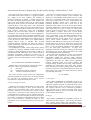
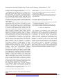
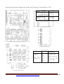
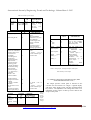
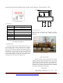
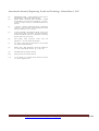
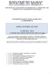
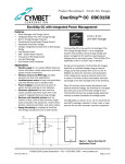
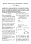
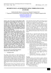
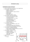
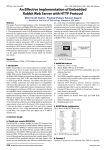
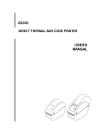
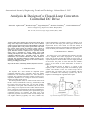
International Journal of Engineering Trends and Technology- Volume3Issue3- 2012
Analysis & Design of a Closed-Loop ConverterControlled DC Drive
Santosh S. raghuwanshi#1, Kamlesh Gupta#2, Sagar Manjrekar#3, Deeksha Choudhary#4 , Yamini Mokhariwale#5
Electrical Engineering Department, RGPV, Bhopal(M.P.)
Sch. No-74C, Sector-D, Vijay Nagar, Indore(M.P.), India
Abstarct- This paper describes the speed control of DC drive
using closed loop control method. In DC drive Armature
voltage control is preferred because of high efficiency and good
speed regulation. But it can provide speed control only below
base (rated) speed because the armature voltage cannot be
allowed to exceed rated value. For speed control above base
speed, field flux control is employed. In a separately excited
motor, flux is controlled by varying voltage across field
winding. The thyristor D.C. drive remains an important speedcontrolled industrial drive, especially where the higher
maintenance cost associated with the D.C. motor brushes is
tolerable. The controlled (thyristor) rectifier provides a lowimpedance adjustable 'D.C.' voltage for the motor armature,
thereby providing speed control.
Keywords- DC Drive, Closed loop method, Thyristor converter
I. INTRODUCTION
The thyristor D.C. drive remains an important speedcontrolled industrial drive, especially where the higher
maintenance cost associated with the D.C. motor brushes is
tolerable. The controlled (thyristor) rectifier provides a lowimpedance adjustable 'D.C.' voltage for the motor armature,
thereby providing speed control.
The motor/generator (MG) set could be sited remote from
the D.C. motor, and multi-drive sites (e.g. steelworks) would
have large rooms full of MG sets, one for each variablespeed motor on the plant. Three machines (all of the same
power rating) were required for each of these 'Ward Leonard'
drives, which was good business for the motor manufacturer.
For a brief period in the 1950s they were superseded by gridcontrolled mercury arc rectifiers, but these were soon
replaced by thyristor converters which covered cheaper first
cost, higher efficiency (typically over 95%), smaller size,
reduced maintenance, and faster response to changes in set
speed. The first and major part of this paper is devoted to
thyristor-fed drives, after which we will look briefly at
chopper-fed drives that are used mainly in medium and small
sizes, and finally turn attention to small servo-type drives.
II. THYRISTOR D.C. DRIVES
For motors up to a few kilowatts the armature converter
can be supplied from either single-phase or three-phase
mains, but for larger motors three-phase is always used. A
separate thyristor or diode rectifier is used to supply the field
of the motor: the power is much less than the armature
power, so the supply is often single-phase, as shown in
Figure a.
The arrangement shown in Figure a. is typical of the
majority of D.C. drives and provides for closed-loop speed
control. The function of the two control loops will be
explored later, but readers who are not familiar with the
basics of feedback and closed-loop systems may find it
helpful to read through the Appendix at this point.
Fig a Schematic diagram of speed-controlled D.C. motor drive
ISSN: 2231-5381 http://www.internationaljournalssrg.org
Page 390
International Journal of Engineering Trends and Technology- Volume3Issue3- 2012
The main power circuit consists of a six-thyristor bridge
circuit which rectifies the incoming A.C. supply to produce a
D.C. supply to the motor armature. The assembly of
thyristors, mounted on a heatsink, is usually referred to as
the 'stack'. By altering the firing angle of the thyristors the
mean value of the rectified voltage can be varied, thereby
allowing the motor speed to be controlled. The controlled
rectifier produces a crude form of D.C. with a pronounced
ripple in the output voltage. This ripple component gives rise
to pulsating currents and fluxes in the motor, and in order to
avoid excessive eddy-current losses and commutation
problems, the poles and frame should be of laminated
construction. It is accepted practice for motors supplied for
use with thyristor drives to have laminated construction, but
older motors often have solid poles and/or frames, and these
will not always work satisfactorily with a rectifier supply. It
is also the norm for drive motors to be supplied with an
attached 'blower' motor as standard. This provides
continuous through ventilation and allows the motor to
operate continuously at full torque even down to the lowest
speeds without overheating.
The combination of power, control, and protective circuits
constitutes the converter. Standard modular converters are
available as off-the-shelf items in sizes from 0.5 kW up to
several hundred kW, while larger drives will be tailored to
individual requirements. Individual converters may be
mounted in enclosures with isolators, fuses etc., or groups of
converters may be mounted together to form a multi-motor
drive.
III. CLOSED-LOOP CONTROL OF DRIVES
Feedback loops in an electrical drive may be provided to
satisfy one or more of the following requirements:
(i)
Protection
(ii)
Enhancement of speed of response
(iii)
To improve steady-state accuracy
This section describes various closed-loop configurations
which find application in electric drives. In all these schemes
the converter and associated control circuit will be
represented by a single block marked converter.
A Closed-Loop Speed control
Closed-loop speed control scheme which is widely used in
electrical drives. It employs an inner current control loop
within an outer speed-loop. Inner current control loop is
provided to limit the converter and motor current or motor
torque below a safe limit. In some schemes the current is
controlled directly. In others it may be controlled indirectly.
For example, in a variable frequency induction motor drives
the current is controlled by controlling the slip. Inner current
loop is also beneficial in reducing the effect on drive
performance of any non-linearity present in converter-motor
system.
An increase in reference speed produces a positive error.
Speed error is processed through a speed controller and
applied to a current limiter which saturates even for a small
speed error. Consequently, limiter sets current reference for
inner current control loop at a value corresponding to the
maximum allowable current. Drive accelerates at the
maximum allowable current (and in some cases at the
maximum torque). When close to the desired speed, limiter
desiderates. Steady-state is reached at the desired speed (with
some steady-state error) and at current for which motor
torque is equal to the load torque. A decrease in reference
speed produces a negative speed error. Current limiter
saturates and sets current reference for inner current loop at a
value corresponding to the maximum allowable current.
Consequently, drive decelerates in braking mode at the
maximum allowable current. When close to the required
speed, current limiter desiderates. The operation is
transferred from braking to motoring. Drive then settles at a
desired speed and at current for which motor torque equals
the load torque. In those drives where the current does not
have to reverse for braking operation, current limiter will
have the input-output characteristics. In those drive
applications where the load torque is able to provide enough
decelerating torque, electric braking need not be used. Then
also current limiter has the characteristic.
Current and speed controller may consists of proportional
and integral (PI), proportional and derivative (PD) or
proportional, integral and derivative (PID) controller,
depending on steady-state accuracy and transient response
requirements. DC drives are widely used in application
requiring adjustable speed, good speed regulation and
frequent starting, braking and reversing. Some important
application are rolling mills, paper mills, mine winders,
hoists, machine tools, traction, printing presses, textile mills,
excavators and cranes. Fractional horsepower dc motors are
widely used as servo motors are widely used as servo motors
for positioning and tracing.
IV. DC DRIVE
A. Description
Series 6RA70 SIMOREG DC MASTER converters are
fully digital, compact units for three-phase-supply which
supply the armature and field of variable-speed DC drives
with rated armature currents of between 15A and 3000A.
The compact converters can be connected in parallel to
supply currents of up to 12000A. The field circuit can be
supplied with currents of up to 85A (current levels depend
on the armature rated current).
B. Design
Series 6RA70 SIMOREG DC MASTER converters are
characterized by their compact, space saving construction.
Their compact design makes them particularly easy to
service and maintain since individual components are readily
ISSN: 2231-5381 http://www.internationaljournalssrg.org
Page 391
International Journal of Engineering Trends and Technology- Volume3Issue3- 2012
accessible. The electronics box contains the basic electronic
circuitry as well as any supplementary boards.
All SIMOREG DC MASTER units are equipped with a
PMU simple operator panel mounted in the converter door.
The panel consists of a five-digit, seven-segment display,
three LEDs as status indicators and three parameterization
keys. The PMU also features connector X300 with a USS
interface in accordance with the RS232 or RS485 standard.
The panel provides all the facilities for making adjustments
or settings and displaying measured values required to start
up the converter.
The OP1S optional converter operator panel can be
mounted either in the converter door or externally, e.g. in the
cubicle door. For this purpose, it can be connected up by
means of a 5 m long cable. Cables of up to 200 m in length
can be used if a separate 5 V supply is available. The OP1S
is connected to the SIMOREG via connector X300. The
OP1S can be installed as an economic alternative to control
cubicle measuring instruments which display physical
measured quantities. The OP1S features an LCD with 4 x 16
characters for displaying parameter names in plaintext.
German, English, French, Spanish and Italian can be selected
as the display languages. The OP1S can store parameter sets
for easy downloading to other devices. The converter can
also be parameterized on a standard PC with appropriate
software connected to the serial interface on the basic unit.
This PC interface is used during start-up, for maintenance
during shutdown and for diagnosis in operation.
Furthermore, converter software upgrades can be loaded via
this interface for storage in a Flash memory. On singlequadrant converters, the armature is supplied via a fully
controlled three-phase bridge B6C and, on four-quadrant
devices, via two fully controlled three-phase bridges in
circulating current- free, inverse-parallel connection
(B6)A(B6)C. The field is supplied via a single-phase,
branch-pair half-controlled 2-pulse bridge connection B2HZ.
The frequencies of the armature and field supply voltages
may be different (in a range from 45 to65 Hz). Operation in
the extended frequency range between 23 Hz and 110 Hz is
available on request. The armature circuit supply phase
sequence is insignificant. For converters with 15A to 850A
(1200A at 400V supply voltage) rated DC current, the power
section for armature and field is constructed of isolated
thyristor modules. The heat sink is thus electrically isolated.
On devices with a higher rated DC current, the power section
for the armature circuit is constructed of disk thyristors and
heat sinks (thyristor assemblies) at voltage potential.
The housing and terminal covers on power connections
provide protection against accidental contact for operators
working in the vicinity. All connecting terminals are
accessible from the front. The power section cooling system
is monitored by means of temperature sensors.
• This device series is available with rated direct currents of
30A to 1200A.
• Devices with rated direct currents of 450A to 1200A are
equipped with a 1-phase fan.
• On devices with rated direct currents of 60A to 850A, the
power terminals are located on the underside and on the
top of the device.
D. Installation Of Simoreg Devices In Cabinets In
Accordance With Ul 508 C Standards
• When the drive is provided in a panel (enclosure), the panel
is ventilated and designated "Type 1".
• The minimum size panel (enclosure) to be used with the
drive is 600 mm length, 600 mm width, 2200 mm height.
V. MODE OF OPERATION
All open-loop and closed-loop drive control and
communication functions are performed by two powerful
microprocessors. Drive control functions are implemented in
the software as program modules which can be "wired up"
by parameters. The rated DC currents (continuous DC
currents), load class Ι, specified on the rated plate can be
exceeded by 180%, the permissible overload during being
dependent on individual converters. The microprocessor
calculates the current I2t value of the power section
cyclically to ensure that the thyristors are not damaged in
overload operation. A selection table for overload operation
can be found in Section 9 “Description of functions".
Converters self-adapt to the frequency of the available
supply voltage in the range from 45 to 65 Hz (armature and
field are independent). Operation in the extended frequency
range between 23 Hz and 110 Hz is available on request.
C. Simoreg Dc Master Operating Instructions
Special features of devices with 460V rated connection
voltage
ISSN: 2231-5381 http://www.internationaljournalssrg.org
Page 392
International Journal of Engineering Trends and Technology- Volume3Issue3- 2012
Function
Terminal
Armature supply input
1U1
1V1
1W1
Armature circuit motor
connection
1C1 (1D1)
1D1 (1C1)
Fig. 3 Field Supply Converter
Fig.1 Block Diagram With Recommended Connection
Fig.4 Description of drive terminals
Table-1 Armature circuit
Table-2 Field circuit
Function
Terminal
Supply
connection
XF1-2
3U1
XF1-1
3W1
Field
winding
connection
XF2-2
3C
XF2-1
3D
Connection
values/Remarks
2AC 400V (– 20%),
2AC 460V (+10%)
Rated DC voltage 325V /
373V
For 2AC 400V / 460V
supply connection
Fig. 2 Armature Convertor Circuit
ISSN: 2231-5381 http://www.internationaljournalssrg.org
Page 393
International Journal of Engineering Trends and Technology- Volume3Issue3- 2012
Table-3 Electronics power supply
Function
connection
Terminal
XP
Connection
values/Remarks
Incoming
supply
400V
1
2
NC
3
5U1
5W1
5N1
2AC 380V (–
25%) to 460V
(+15%
);
In=1A(–
35%
for 1min)
Function
Terminal
XT
34
Supply (output)
Ground digital M
35
Select input binary 1
Power On / Shutdown
H signal: Power ON
Line contactor
CLOSED +
(with H signal at
terminal 38),
acceleration along
ramp function
generator ramp to
operating speed.
L signal: Shutdown
Deceleration along
ramp function
generator ramp to
n < n min (P370) + ,
controller
disable + line
contactor OPEN.
Enable operation
H signal: Controller
enabled
L signal: Controller
disabled
See Section 9.3.4 for
exact
function description
Select input binary 2
Function
Tacho
connection 8V
to 270V
Ground analog
M
36
37
Connection
values/Remarks
24V DC, short circuit
proof
max. load 200mA
(terminals 34, 44, and
210 combined),
internal supply with
respect to internal
ground
Overload response:
Error signal F018
Warning signal A018
H signal: +13V to
+33V
L signal: – 33V to
+3V or terminal open
8.5mA at 24V
Function
Terminal
X174
Reference
M
P10
N10
1
2
3
Select
input
main setpoint +
4
5
main setpoint –
6
7
Select
input
analog 1 +
analog 1 –
Connection
values/Remarks
±1% at 25°C (stability
0.1% per 10°K); 10mA
shortcircuit-proof
Input type (signal type)
parameterizable:
Differential
input
±10V; 150kΩ
- Current input 0 20mA; 300Ω or
4 - 20mA; 300Ω
Resolution
can
be
parameterized up to
approx. 555µV
(±14bit)
Common
mode
suppression: ±15V
Table-5 Analog inputs - actual speed inputs, tacho inputs
Table-6 Binary control inputs
VI. SIMPLE OPERATOR CONTROL PANEL (PMU
“PARAMETERIZATION UNIT“)
38
39
Terminal
XT
103
104
H signal: +13V to
+33V
L signal: – 33V to
+3V or terminal open
8.5mA at 24V
Connection
values/Remarks
±270V; >143kΩ
Table-4
Analog
inputs –
set point
inputs,
reference
voltage
The simple operator control panel is mounted in the
converter door and consists of a 5-digit, 7- segment display
with three status display LEDs and three parameterization
keys below. All adjustments and settings that need to be
undertaken for the purpose of start-up can be made on the
simple control panel.
ISSN: 2231-5381 http://www.internationaljournalssrg.org
Page 394
International Journal of Engineering Trends and Technology- Volume3Issue3- 2012
Fig.5 Parameterization Unit
A. LED Display
Run green LED
LED
illuminated
Ready yellow
LED
LED
illuminated
Fault red LED
LED
illuminated ⇒
LED flashing ⇒
Fig. 6 Drive Connection
In “Torque direction
active” state.
B. Complete Setup
In “Ready” state.
Fig.7 shows the complete setup of Simoreg DC drive
connecting with DC motor with suitable measuring
instruments
In “Fault signal present” .
An alarm is active.
VII. WIRING DIAGRAM
A. DRIVE PANEL
3 AC 50 Hz 440V is given to Input terminal of drive 1U1,
1V1 and 1W1. This is input of dual-convertor. Output is
taken from terminal 1C1 (1D1) and 1D1 (1C1) which is
given to motor armature terminals with suitable measuring
instruments. 2 AC 50 Hz 440 V is given to Terminal 3U1
and 3W1 this is input of semi-convertor used by drive and
output is taken out from terminals 3D and 3C which is given
to motor field windings. 5U1 and 5W1 is fed with 2 AC 50
Hz 440V this is power electronic supply of drive.
Fig.7 Complete Setup
VIII CONCLUSION
Armature voltage control is preferred because of high
efficiency and good speed regulation. But it can provide
speed control only below base (rated) speed because the
armature voltage cannot be allowed to exceed rated value.
For speed control above base speed, field flux control is
employed. In a separately excited motor, flux is controlled
by varying voltage across field winding.
REFERENCE
[1]
Gopal K. Dubey, “Fundamentals of Electric Drives”, .Narosa
Publishing House New Delhi,1989.
ISSN: 2231-5381 http://www.internationaljournalssrg.org
Page 395
International Journal of Engineering Trends and Technology- Volume3Issue3- 2012
[2]
[3]
Muhammad H. Rashid, ‘‘Power Electronics Circuits, Devices,
and Applications,” Prentice Hall, 3rdedition, 2003.
Kumara MKSC, Dayananda PRD, Gunatillaka
MDPR,
Jayawickrama SS, “PC based speed controlling of a dc motor”,
A fmal year report University of Moratuwa Illiniaus USA,
2001102.
[4]
J. Chiasson, Nonlinear Differential-Geometric Techniquesfor
Control of a Series DC Motor, IEEE Transactionson Control
Systems Technology.vol 2, p. 35-42,1994.
[5]
A Khoei Kh.Hadidi, “MicroProcessor Based Closed- Loop
Speed Control System for DC Motor Using Power MOSFET”,
3rd IEEE international conference on Electronics, Circuits and
Systems( 1996) vol.2, pp.1247-1250.
[6]
M.H. Rashid, “Power Electronics circuits,
application”, 3rd Ed., 2007, Pearson Prentice Hall.
[7]
S. K. Pillai, “A first course on electrical drives”, II nd Ed. 2004,
New Age International Publication.
[8]
Bimal K. Bose, “High Performance control and estimation in
A.C. drives”, IEEE IECON Conf. Rec., pp. 377-385, 1997
[9]
Micromaster440 user manual by Siemens.
[10]
Simrog dc mater user manual by Siemens.
[11]
J. M. D. Murphy, F. G. Turnbull, “Power Electronic control of
A.C. motors”, Pergamon Press
drives
and
ISSN: 2231-5381 http://www.internationaljournalssrg.org
Page 396