1
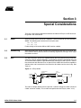
ATICE10
.............................................................................
User Guide
Table of Contents
Section 1
Introduction ........................................................................................... 1-1
1.1
1.2
1.3
1.4
1.5
1.6
1.7
General Description ..................................................................................1-1
External Connections ................................................................................1-2
Power System ...........................................................................................1-2
Reset System............................................................................................1-2
Trace Buffer ..............................................................................................1-3
External Triggers.......................................................................................1-3
Preparing the ICE10 System for Use ........................................................1-4
Section 2
Emulating ATtiny15............................................................................... 2-1
2.1
2.2
The ATtiny15POD.....................................................................................2-1
Configuration of the ATtiny15POD............................................................2-1
2.2.1
Device.................................................................................................2-1
2.2.2
Enable External Reset........................................................................2-1
2.3
Connecting to the System .........................................................................2-2
Section 3
Special Considerations ......................................................................... 3-1
3.1
3.2
3.3
3.4
3.5
Stack .........................................................................................................3-1
Assembling ...............................................................................................3-1
ADC ..........................................................................................................3-1
Noise Canceler Mode ...............................................................................3-2
Timer/Counter1 .........................................................................................3-2
Section 4
Troubleshooting Guide ......................................................................... 4-1
Section 5
Connector Description .......................................................................... 5-1
5.0.1
Logic Analyzer 1 .................................................................................5-1
5.0.2
Logic Analyzer 2 .................................................................................5-2
5.0.3
Aux Connector....................................................................................5-2
Section 6
Technical Specifications ....................................................................... 6-1
i
Table of Contents
ii
Section 1
Introduction
1.1
General
Description
The Atmel AVR ® ATICE10 is a real-time in-circuit emulator for ATtiny devices. The
ICE10 is controlled by AVR Studio, version 3.0 and later. The ICE10 currently supports
the following device:
■
ATtiny15
This document describes the configuration and setup of the ICE10 and configuration of
AVR Studio to support emulation of this device. The ICE10 consists of the following
components:
■
ICE10 emulator unit
■
Pod card ATtiny15POD
■
Pod cable
■
ATtiny15 probe with cable
■
RS-232 cable
■
Power supply unit
■
Documentation
The ICE10 emulator unit is the main part of the AVR ICE10 system. The ICE unit is controlled by AVR Studio, which runs on a host PC. The AVR Studio automatically detects if
there is an emulator present on one of the PC’s serial ports. Note that if no ICE is
detected, AVR Studio will show Simulator in the lower right corner of the main window.
If the ICE10 is detected, AVR Emulator will be indicated and your connections are correct. The AVR Studio will issue a warning if a program previously run in emulator mode
is started in simulator mode.
AVR® ATICE10 User Guide
1-1
Rev. 1632A-02/00
Introduction
1.2
External
Connections
The ICE unit is connected to an RS-232 port on the host PC with the supplied RS-232
cable. The connection on the back panel is shown in Figure 1-1. The Parallel Port and
AVR Prog. connectors have no function on this ICE. Two reset buttons are placed on
the back panel of the ICE unit. The AVR RESET button resets the application. The ICE
RESET button resets both the ICE unit and the application.
Figure 1-1. ICE Unit Back Panel
The ICE unit front panel is shown in Figure 1-2. Two LEDs on the front panel indicate
the status of the emulator. After power-up, the red LED will be lit, indicating that the
power supply is OK and the green LED is turned on after a few seconds when initialization and self-test are finished.
Figure 1-2. ICE Unit Front Panel
The emulator pod is connected to the POD connector on the ICE unit. The LOGIC
ANALYZER and AUX connectors are described later. See “Connector Description” in
Section 5.
1.3
Power System
The ICE10 system has an internal power regulator that delivers 15W at 5V. The ICE10
itself uses about 10W. The power supply delivered with the ICE10 is dimensioned to
meet the requirements of the emulator. If another power supply is used, it should supply
a voltage between 9 and 15VDC and a minimum of 20W. The battery eliminator connector on the ICE10 system is a standard type with 2.1 mm center tap. Ground should be
connected to the center tap.
Note:
1.4
Reset System
The target application power must not be present when the emulator is turned
off, as this may cause damage to the pod.
The ICE10 has two independent reset systems. One is for the ICE10 itself and the other
is for the emulated AVR device. The ICE10 reset button is placed on the back panel of
the box. The button is labeled ICE RESET and is hidden in the back panel for safety reasons. If the emulator starts to behave unpredictably, use a thin tool to push this reset
button. The green LED will be turned off for a while and will be switched on again when
the system is ready. When the ICE10 reset button is pressed, the program memory is
cleared, thus the project file must be closed in AVR Studio and then reopened.
The AVR reset system can reset the emulated device both when the device is running
and stopped. This reset can be activated from several sources:
1-2
■
The push-button marked AVR RESET on the back panel of the AVR ICE unit
(only when running)
■
The push-button marked RESET on the pod (only when running)
AVR® ATICE10 User Guide
Introduction
■
The reset button in AVR Studio. Note that the reset button in AVR Studio will stop the
emulation process if it is running when the button is pushed.
■
A reset signal from the user application (only when running)
Note:
In order to enable external reset, the Enable External Reset option must be
selected in the AVR Studio Emulator Options dialog.
Please note that only a reset from the user application will reset other components in the
application connected to the AVR’s reset pin.
1.5
Trace Buffer
The ICE10 has a 32K x 96-bit trace buffer that stores information about program execution for every clock cycle. When the emulator is stopped, this trace buffer can be
examined to extract information about the history of the emulated program. The details
on which data are stored and how to retrieve them are described in the “AVR Studio
User Guide.” When the trace buffer is full, it will wrap around and start overwriting the
oldest entries.
The trace buffer can be turned on or off at any program line. This makes it possible to
skip tracing delay loops and other subroutines which would otherwise fill the trace memory with unnecessary data. The trace buffer is inactive by default. To trace an entire
program, a Trace on marker should be placed on the first line of the program.
1.6
External Triggers The ICE10 has five external trigger inputs and five trigger outputs, all located on the Aux
connector next to the Pod connector.
■
The trigger inputs can act as break signals to the emulator and/or they can be logged
in the trace buffer. Any inputs set up to break the emulator are activated when a rising
edge is detected.
■
The trigger outputs may be set as trigger points on any instruction in the code window
in AVR Studio. If enabled on an instruction, the output(s) will remain high for one AVR
clock cycle when the marked instruction is executed. This can be used to trigger a
logic analyzer or an oscilloscope.
The details on how to enable and set up triggers and mask registers are presented in
AVR Studio Help. There are three global mask registers that are used to control the
behavior of the triggers:
■
The Trigger Output Global Mask Register controls which of the output pins are
allowed to be controlled by the trigger settings in the code. An output pin that is
disabled will remain low even if a trigger point for that particular pin is set in the code.
■
The Trigger Input Global Mask Register controls which of the input pins are allowed to
break the emulator. If more than one line is enabled, the emulator will break on either
one, but will not store any information about which input caused the event. Note that
unconnected inputs are pulled high by internal pull-up resistors. Unused lines must
not be enabled.
■
The External Trace Mask Register controls which of the input pins will be stored in the
trace memory. Input pins that are not enabled in this register will be stored as zero in
the trace memory. To be traced, input signals must be valid and stable at the rising
edge of the AVR clock and for 50 ns thereafter. It is also necessary that the trace
buffer is enabled.
The trigger input and the external trace are two independent functions acting on the
same input pins. Note that the trigger logic is asynchronous and edge driven, whereas
the trace logic is clocked on the AVR clock. The emulator may therefore break on a
glitch signal that is too narrow to be traced.
AVR® ATICE10 User Guide
1-3
Introduction
1.7
1-4
Preparing the
Complete the following procedure in order to start using the ICE10. Before connecting
ICE10 System for the probe cable to the user application:
■ Connect the RS-232 cable between the ICE10 unit and the PC serial port.
Use
■
Connect the pod card to the ICE10 unit with the supplied pod cable.
■
Connect the probe cable to the pod.
■
Connect the enclosed power supply (9 - 15VDC) to the ICE10 unit.
■
Turn on the power and check that the red LED marked POWER is lit.
■
After a short time (<10 s), the green LED marked READY will be lit and the ICE10
system will be ready.
■
Turn off the power.
■
Plug the probe into the application/adapter. The target power should under no
circumstance be present when the probe is connected and the emulator is switched
off. Pay attention to connect it in the correct orientation. If it is not connected correctly,
the ICE10 system may be damaged.
■
Make sure that the AVR Studio pod settings are set according to the requirements.
■
Turn on the power.
■
Connect power to the target application.
■
Start AVR Studio.
AVR® ATICE10 User Guide
Section 2
Emulating ATtiny15
2.1
The
ATtiny15POD
To emulate ATtiny15, the ATtiny15POD should be used. The ATtiny15POD is fully configurable from AVR Studio.
The ATtiny15POD has a reset button and this can be used to reset the application when
it is running.
2.2
Configuration of The ATtiny15POD is configured directly from AVR Studio. When an object file is opened
the ATtiny15POD in AVR Studio for the first time, a dialog box with the ICE10 emulator options is displayed (Figure 2-1). The option can also be changed later from the Options > Emulator
Options menu.
Figure 2-1. Emulator Options Dialog
2.2.1
Device
Select the device from the list. The device list includes all devices currently supported in
the emulator.
2.2.2
Enable External
Reset
If PortB5 of ATtiny15 should be used as reset pin, this selection should be checked. If
not checked, PINB5 functions as an input or an open-drain output. In the actual device,
this is controlled by the RSTDISBL fuse.
AVR® ATICE10 User Guide
2-1
Emulating ATtiny15
2.3
Connecting to
the System
The pod card is connected to the Pod connector of ICE10 using the pod cable (the wide
cable). The 8-lead probe cable should be connected between the ATtiny15POD and the
target application.
The application should provide its own power supply.
Note:
It is important that the probe is correctly connected to the user application. If
not, the pod may be damaged.
WARNING: Turn off power to the target application before the emulator is
turned off.
2-2
AVR® ATICE10 User Guide
Section 3
Special Considerations
There are a few important differences between emulation of ATtiny15 in ICE10 and running code in the actual device.
3.1
Stack
There is no HW stack in the ICE10. Therefore, a stack must be set up in the emulator’s
SRAM. The following two instructions will set up the stack.
ldi r16, $6F
out $3D, r16
Further writing to I/O location $3D and $3E must be avoided.
3.2
Assembling
Some instructions that are not available in tiny AVR devices will work in the ICE10. Use
the assembler device directive when assembling to generate warnings when illegal
instructions are used.
3.3
ADC
The ADC featured in ATtiny15 is implemented on the ATtiny15POD using an AD converter chip, several analog multiplexers, an operational amplifier to provide 20x gain and
an instrumentation amplifier to provide differential mode inputs. See Figure 3-1. Due to
this construction with discrete ICs on an open PCB, the ADC will be more susceptible to
ambient noise and have electrical characteristics that differ from the actual chip. See
Table 3-1.
Figure 3-1. ATtiny15POD
Gain
Selection
Instrumentation
Amplifier
ADC0
ADC1
ADC2
ADC3
Gain Amplifier
+
-
10-bit ADC AREF
10x
Int. Ref
AREF
AVCC
The internal voltage reference on the pod has a nominal voltage of 2.495V (minimum
2.440V, maximum 2.550V). This is within the specification of ATtiny15 (2.40V - 2.7V).
AVR® ATICE10 User Guide
3-1
Special Considerations
When measuring differential signals, the lowest possible signal is approximately 8 mV.
For any signals below this value, the voltage output of the instrumentation amplifier will
be 8 mV (maximum). When measuring single-ended signals, the instrumentation amplifier is bypassed and the signal may be in the range 0V to VREF.
The differential amplifier and gain stages are supplied with 7V on the pod. To protect the
ADC chip from any voltage levels exceeding 5.8V (for instance, when using 20x amplification and an input signal >0.29V), a clamping diode and a series resistor of 51Ω are
coupled to the ADC input pin.
Note:
The signal applied to the ADC inputs multiplied with the selected gain (1x or
20x) should never exceed 5.5VDC.
The multiplexer selecting the reference voltage to the ADC has internal clamping diodes
to VCC on all inputs. If target VCC is present and the emulator power is switched off, the
clamping diodes will conduct current directly to GND. To limit this current, two 470Ω
resistors are coupled in series with external reference signal. See Figure 3-1.
Under no circumstances should the target power be present while the emulator is
switched off.
IMPORTANT: In a critical application using ADC (for instance, a battery charger charging LiIon batteries), the emulator should not be used as a replacement for the actual
device during testing due to inaccuracy and noise in the ADC.
Table 3-1. ADC Characteristics (only values differing from the actual device are
displayed)
Parameter
Condition
Min
Typ
Max
Units
Single-ended
0
5.5
V
Differential 1x
0.008
5.5
V
Differential 10x
8
550
mV
Differential 200x
8
27.5
mV
AREF
1.2
5.5
V
VINT
2.440
2.495
2.550
V
VBG
1.20
1.25
1.29
V
VIN
VREF
Normal operation
1M
ohm
Target VCC present, emulator turned off
470
ohm
3.4
Noise Canceler
Mode
The ADC noise canceler mode featured in ATtiny15 is implemented as idle mode in
ICE10, not power-down mode as in the actual device.
3.5
Timer/Counter1
Due to synchronization of the CP U and Timer/Counter 1, data written into
Timer/Counter1 is delayed by one CPU clock cycle. This applies to both the ATtiny15
device and ICE10 emulating ATtiny15. Due to this synchronization mechanism, values
written to TCNT1 in AVR Studio’s I/O view will not be updated before the program is
single speed or another I/O location is written.
3-2
AVR® ATICE10 User Guide
Section 4
Troubleshooting Guide
Table 4-1. Troubleshooting
AVR® ATICE10 User Guide
Problem
Solution
The red LED is not lit when
the power is turned on
- Check that the power cord is properly inserted in the wall
- Check that the power plug is properly inserted in the ICE
- Check that you are using a power supply with negative center
on the DC output
When a file is opened in
AVR Studio, it starts in
simulator mode
- Check that the serial cable is inserted in the PC and the ICE
- Restart the PC with the ICE serial cable connected to the
serial port to make sure no other devices (mouse, etc.) are
using the serial port
- Disconnect the pod from the emulator and restart the
emulator
After performing an upgrade
of the ICE from AVR Studio,
the green LED is not lit when
the power is turned on
- Wait 10 seconds
- Restart the emulator
- Perform the upgrade again
The application is not
running in AVR Studio
- Make sure the target VCC is connected or that the application
is powered by the emulator
- Make sure the target clock is connected or internal clock is
selected in AVR Studio
- Disconnect the pod and try again; if it is working now, the
problem is in the application
AVR Studio shows the
message “Error
communicating with the
emulator” when trying to
download the code
- Check serial cable connections
- Make sure the pod is correctly connected to the emulator and
the target
- Make sure the target power is present (LED lit on the pod)
- Restart the emulator
4-1
Troubleshooting Guide
4-2
AVR® ATICE10 User Guide
Section 5
Connector Description
5.0.1
Logic Analyzer 1
Figure 5-1. Logic Analyzer 1 Connector
The connector marked LOGIC ANALYZER 1 on the back panel of the AVR ICE unit has
the following pinout with signals from the instruction address bus.
Table 1. Pinout for Logic Analyzer 1
Signal
AVR® ATICE10 User Guide
Logic Analyzer 1
Signal
AVRCLK
Pin 1
Pin 2
Low
Low
Pin 3
Pin 4
A15
A14
Pin 5
Pin 6
A13
A12
Pin 7
Pin 8
A11
A10
Pin 9
Pin 10
A9
A8
Pin 11
Pin 12
A7
A6
Pin 13
Pin 14
A5
A4
Pin 15
Pin 16
A3
A2
Pin 17
Pin 18
A1
A0
Pin 19
Pin 20
GND
5-1
Connector Description
5.0.2
Logic Analyzer 2
Figure 5-2. Logic Analyzer 2 Connector
The connector marked LOGIC ANALYZER 2 on the back panel of the AVR ICE unit has
the following pinout with signals from the instruction data bus.
Table 5-1. Pinout for Logic Analyzer 2
Signal
5.0.3
Aux Connector
Logic Analyzer 2
Signal
AVRCLK
Pin 1
Pin 2
Low
Low
Pin 3
Pin 4
D15
D14
Pin 5
Pin 6
D13
D12
Pin 7
Pin 8
D11
D10
Pin 9
Pin 10
D9
D8
Pin 11
Pin 12
D7
D6
Pin 13
Pin 14
D5
D4
Pin 15
Pin 16
D3
D2
Pin 17
Pin 18
D1
D0
Pin 19
Pin 20
GND
Figure 5-3. Aux Connector
The connector marked AUX on the back panel of the AVR ICE unit is used for external
triggers and has the following pinout.
Table 5-2. Pinout for Aux Connector
Signal
5-2
Aux
Signal
GND
Pin 1
Pin 2
GND
Input 0
Pin 3
Pin 4
Output 0
Input 1
Pin 5
Pin 6
Output 1
Input 2
Pin 7
Pin 8
Output 2
Input 3
Pin 9
Pin 10
Output 3
Input 4
Pin 11
Pin 12
Output 4
GND
Pin 13
Pin 14
GND
AVR® ATICE10 User Guide
Section 6
Technical Specifications
System Unit
Physical Dimensions . . . . . . . . (H x W x D) 32.4 x 277.1 x 218.6 mm/1.3 x 10.8 x 8.5 in
Weight . . . . . . . . . . . . . . . . . . . . . . . . . . . . . . . . . . . . . . . . . . . . . . . . . . . . 400 g/0.88 lbs
Power Voltage Requirements . . . . . . . . . . . . . . . . . . . . . . . . . . . . . . . . . . . . . . 9 - 15VDC
Power Consumption . . . . . . . . . . . . . . . . . . . . . . . . . . . . . . . . . . . . . . . . . . . . . . . < 20W
ICE Power Consumption . . . . . . . . . . . . . . . . . . . . . . . . . . . . . . . . . . . . . . . . . . . . . . 10W
Max. Application Power Consumption. . . . . . . . . . . . . . . . . . . . . . . . . . . . . . . . . . . . . 5W
Ambient Temperature . . . . . . . . . . . . . . . . . . . . . . . . . . . . . . . . . . 0 - +70°C (Operating)
. . . . . . . . . . . . . . . . . . . . . . . . . . . . . . . . . . . . . . . . . . . . . . -55 - +85°C (Non-operating)
Relative Humidity (Non-condensing) . . . . . . . . . . . . . . . . . . . . . . . . 10 - 90% (Operating)
. . . . . . . . . . . . . . . . . . . . . . . . . . . . . . . . . . . . . . . . . . . . . . . . . 5 - 95% (Non-operating)
Shock . . . . . . . . . . . . . . . . . . . . . . . . . . . . . . . . . . . . . . . . . . . . . . . 20 g, 11 ms half sine
Vibration . . . . . . . . . . . . . . . . . . . . . . . . . . . . . . . . . . . . . . . . . . . . . . . . . . . . . . . . . . . 5 g
Connections
Power
Connector . . . . . . . . . . . . . . . . . . . . . . . . . . . . . 5.5 mm OD/2.1 mm ID Center Negative
Host
Serial Connector (RS-232) . . . . . . . . . . . . . . . . . . . . . . . . . . . . . . . 9-pin D-SUB Female
Serial Communications Speed . . . . . . . . . . . . . . . . . . . . . . . . . . . . . . . . . . . 19200 bits/s
Pod
Connectors . . . . . . . . . . . . . . . . . . . . . . . . . . . . . . . . . . . . . one/two 2 x 32 Male Header
External Trigger Inputs/Outputs
Connector . . . . . . . . . . . . . . . . . . . . . . . . . . . . . . . . . . . . . . . . . . . . . . 2 x 7 Male Header
Logic Analyzer Interface
Connectors . . . . . . . . . . . . . . . . . . . . . . . . . . . . . . . . . . . . . . . . two 2 x 10 Male Headers
Clock Specification
Internal Clock
Minimum Frequency . . . . . . . . . . . . . . . . . . . . . . . . . . . . . . . . . . . . . . . . . . . . . . 400 kHz
Maximum Frequency . . . . . . . . . . . . . . . . . . . . . . . . . . . . . . . . . . . . . . . . . . . . . 20.0 MHz
External Crystal
Minimum Frequency . . . . . . . . . . . . . . . . . . . . . . . . . . . . . . . . . . . . . . . . . . . .32.768 kHz
Maximum Frequency . . . . . . . . . . . . . . . . . . . . . . . . . . . . . . . . . . . . . . . . . . . . . 10.0 MHz
AVR® ATICE10 User Guide
6-1
Technical Specifications
Internal Watchdog RC Oscillator
Running Frequency . . . . . . . . . . . . . . . . . . . . . . . . . . . . . . . . . . . . . . . . . 1.0 MHz ± 30%
Operation
Minimum Running Speed . . . . . . . . . . . . . . . . . . . . . . . . . . . . . . . . . . . . . . . .32.768 kHz
Maximum Running Speed . . . . . . . . . . . . . . . . . . . . . . . . . . . . . . . . . . . . . . . . . 12.0 MHz
Minimum Single-step Speed . . . . . . . . . . . . . . . . . . . . . . . . . . . . . . . . . . . . . .32.768 kHz
Maximum Single-step Speed . . . . . . . . . . . . . . . . . . . . . . . . . . . . . . . . . . . . . . 10.0 MHz
Minimum Breakpoint Speed . . . . . . . . . . . . . . . . . . . . . . . . . . . . . . . . . . . . . .32.768 kHz
Maximum Breakpoint Speed . . . . . . . . . . . . . . . . . . . . . . . . . . . . . . . . . . . . . . . 10.0 MHz
Memory Specification
Program Memory. . . . . . . . . . . . . . . . . . . . . . . . . . . . . . . . . . . . . . . . . . . . . . .128K bytes
Event Memory . . . . . . . . . . . . . . . . . . . . . . . . . . . . . . . . . . . . . . . . . . . . . . . . .128K bytes
EEPROM Memory . . . . . . . . . . . . . . . . . . . . . . . . . . . . . . . . . . . . . . . . . . . . . . .64K bytes
SRAM Memory . . . . . . . . . . . . . . . . . . . . . . . . . . . . . . . . . . . . . . . . . . . . . . . . .64K bytes
Register File . . . . . . . . . . . . . . . . . . . . . . . . . . . . . . . . . . . . . . . . . . . . . . . . . . . . 32 bytes
I/O Area . . . . . . . . . . . . . . . . . . . . . . . . . . . . . . . . . . . . . . . . . . . . . . . . . . . . . . . . 64 bytes
Trace Buffer Memory. . . . . . . . . . . . . . . . . . . . . . . . . . . . . . . . . . . . . . . . . 32K x 12 bytes
I/O Pins
Output Level . . . . . . . . . . . . . . . . . . . . . . . . . . . . . . . . . . TTL/CMOS (VCC: 2.7 - 5.5VDC)
Maximum Sink Current . . . . . . . . . . . . . . . . . . . . . . . . . . . . . . . . . . . . . . . . . . . . . 24 mA
Maximum Source Current . . . . . . . . . . . . . . . . . . . . . . . . . . . . . . . . . . . . . . . . . . . 10 mA
Permanent Pull-up. . . . . . . . . . . . . . . . . . . . . . . . . . . . . . . . . . . . . . . . . . . . . . . . . 1.0 MΩ
6-2
AVR® ATICE10 User Guide
Atmel Headquarters
Atmel Operations
Corporate Headquarters
Atmel Colorado Springs
2325 Orchard Parkway
San Jose, CA 95131
TEL (408) 441-0311
FAX (408) 487-2600
Europe
1150 E. Cheyenne Mtn. Blvd.
Colorado Springs, CO 80906
TEL (719) 576-3300
FAX (719) 540-1759
Atmel Rousset
Atmel U.K., Ltd.
Coliseum Business Centre
Riverside Way
Camberley, Surrey GU15 3YL
England
TEL (44) 1276-686-677
FAX (44) 1276-686-697
Zone Industrielle
13106 Rousset Cedex
France
TEL (33) 4-4253-6000
FAX (33) 4-4253-6001
Asia
Atmel Asia, Ltd.
Room 1219
Chinachem Golden Plaza
77 Mody Road Tsimhatsui
East Kowloon
Hong Kong
TEL (852) 2721-9778
FAX (852) 2722-1369
Japan
Atmel Japan K.K.
9F, Tonetsu Shinkawa Bldg.
1-24-8 Shinkawa
Chuo-ku, Tokyo 104-0033
Japan
TEL (81) 3-3523-3551
FAX (81) 3-3523-7581
Fax-on-Demand
North America:
1-(800) 292-8635
International:
1-(408) 441-0732
e-mail
[email protected]
Web Site
http://www.atmel.com
BBS
1-(408) 436-4309
© Atmel Corporation 2000.
Atmel Corporation makes no warranty for the use of its products, other than those expressly contained in the Company’s standard warranty which is detailed in Atmel’s Terms and Conditions located on the Company’s web site. The Company assumes no responsibility for
any errors which may appear in this document, reserves the right to change devices or specifications detailed herein at any time without
notice, and does not make any commitment to update the information contained herein. No licenses to patents or other intellectual property of Atmel are granted by the Company in connection with the sale of Atmel products, expressly or by implication. Atmel’s products are
not authorized for use as critical components in life suppor t devices or systems.
Marks bearing
®
and/or
™
are registered trademarks and trademarks of Atmel Corporation.
Terms and product names in this document may be trademarks of others.
Printed on recycled paper.
1632A–02/00/xM