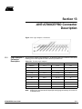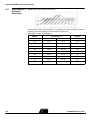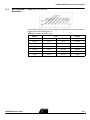
1
Section 1
Introduction
The AT90ICEPRO is a real time In-Circuit Emulator (ICE) for all AT90S1200, -S2313,
-S2323, -S2333, -S2343, -S4414, -S4433, -S4434, -S8515 and -S8535 devices. It can
be upgraded to support future AVR® parts. It is controlled by AVR Studio, which is a professional front-end for both high-level and assembly level debugging. AVR Studio is
described in Section 1 in the Development Tools User Guide and must be studied carefully in order to take full advantage of this product.
The AVR AT90ICEPRO ICE system consist of the following elements:
■ AVR ICE Unit
AT90ICEPRO User Guide
■
Pod card AT90ADCPOD
■
Pod Cable
■
AT90S1200/-2313 probe with cable (DIL20)
■
AT90S4414/-8515/-4434/-8535 probe with cable (DIL40)
■
AT90S2323/-2343 probe with cable (DIL8)
■
AT90S2333/-4433 probe with cable (DIL28)
■
A RS-232 cable
■
A Power Supply unit
■
Documentation
1-1
Rev. 1024B–01/99
Introduction
Figure 1-1. AVR AT90ICEPRO with AT90ADCPOD
The AVR ICE unit is the main part of the AVR AT90ICEPRO system. AVR Studio, which
runs on a host PC, controls the ICE unit. The AVR ICE unit must be connected to an
available RS-232 port on the host PC with the supplied RS-232 cable. AVR Studio automatically detects if there is an emulator present on one of the PC’s serial ports. Note
that if no ICE is found, AVR Studio will show “Simulator” in the lower right corner of the
main window. If the ICE is found, “AVR Emulator” will be indicated and your connections
are correct. AVR Studio will issue a warning if a program previously run in emulator
mode is started in simulator mode.
1-2
AT90ICEPRO User Guide
Introduction
Figure 1-2. AT90ADCPOD
AT90ADCPOD is the pod card used for the processors, AT90S1200, -S2313, -S2323, S2333, -S2343, -S4414, -S4433, -S4434, -S8515, and -S8535. The pod contains the
analog comparator, the analog to digital converter, a clock circuit for handling of XTAL
and TOSC signals from the target application, a reset button and a voltage conversion
circuit. 11 different jumpers and one switch can be set on the pod card to select between
the different functions.
The pod card is connected to the AVR ICE unit using the pod cable (the wide cable),
and to the user application using the 8-pin, 20-pin, 28-pin, or 40-pin probe.
Note: It is extremely important that the probe cable is correctly connected to the user
application. The colored wire of the probe cable indicates pin 1 of the AVR
device.
Figure 1-3. AVR ICEPRO Front Panel
Figure 1-4. AVR ICEPRO Back Panel
AT90ICEPRO User Guide
1-3
Introduction
1-4
AT90ICEPRO User Guide
Section 2
Preparing the AVR AT90ICEPRO
System for Use
Complete the following procedure in order to start using the AVR ICE.
Before connecting the probe cable to the user application:
■ Connect the pod card to the AVR ICE unit with the pod cable.
■
Connect the appropriate probe to the pod.
■
Connect the RS-232 cable between the AVR ICE unit and an available serial port on
the host PC.
■
Connect power supply (9 - 15 VDC) to the AVR ICE unit.
■
Turn the power on and check that the red LED marked “POWER” is lit.
■
After a short time (≤10 sec.), the green LED marked “READY” will be lit and the AVR
ICEPRO system is ready.
■
Turn off the power.
Plug the probe into the application, paying attention to connect it correctly. If it is not
connected correctly, the AVR AT90ICEPRO system may be damaged. The colored wire
of the probe cable indicates pin 1 of the AVR device.
■ When the probe is correctly connected to the application, check the jumper marked
“EXT. POWER” on the probe circuit board. If the application is powered from the AVR
ICE unit, the jumper must be mounted. If the application is going to use its own power
supply, the jumper must be removed.
■
Make sure that all other jumpers and switches (clock, timer, analog comparator and
device) are set according to your application. Details on these jumper settings are
located in Section 4.
■
When all jumpers are set correctly, turn on the power. When the green LED is lit, the
AVR AT90ICEPRO system is ready for use. Start AVR Studio, and begin your AVR
emulation session.
AT90ICEPRO User Guide
2-1
2-2
AT90ICEPRO User Guide
Section 3
Select Between
Different AVR Devices
The selection between different AVR devices must be done both in AVR Studio and on
the pod card. In AVR Studio, choose the device you want to emulate in the Device menu
in Emulator Options. On the pod card, make sure to use the appropriate probe cable (20
pins for 20 pin device and so on) and connect your application to the connector labeled
with the correct part number. Please note that it may damage your AT90ICEPRO if you
plug the probe cable into the wrong connector.
To use AT90S2323 ar AT90S2343, the jumpers on the connectors labeled PB3 and
PB4 must be set. Table 3-1 below shows how to set these jumpers.
Table 3-1. Jumper Settings when Selecting between AT90S2323 and AT90S2343
Device
PB3
PB4
AT90S2323
OFF
OFF
AT90S2343 with external clock
OFF
ON
AT90S2343 with internal clock
ON
ON
For other devices these jumpers are not used.
To use AT90S2333, AT90S4433, AT90S4434 or AT90S8535, the 10 lead cable on the
pod must be mounted. Table 3-2 below shows where to connect this cable.
Table 3-2. Connections of 10-lead cable
Device
10-lead cable
AT90S2333 or AT90S4433
ADC and ADC28
AT90S4434 or AT90S8535
ADC and ADC40
For other devices this cable is not used.
AT90ICEPRO User Guide
3-1
3-2
AT90ICEPRO User Guide
Section 4
The AVR AT90ICEPRO
Power System
The AVR AT90ICEPRO system has an internal power regulator that can deliver 15W of
power at 5V. The AVR ICE itself uses about 10W, so if the user application is powered
from the AVR AT90ICEPRO system, it can not use more then 5 W (i.e. 5V/1A). If this
value is exceeded, the AVR AT90ICEPRO system may be damaged or not work properly.
The power supply delivered with your AT90ICEPRO is dimensioned to meet the requirements of the emulator. If another power supply is used, it should supply a voltage
between 9 and 15 VDC, and minimum 20W. The battery eliminator connector on the AVR
AT90ICEPRO system is a standard type with 2.1 mm center tap. Ground should be connected to the center tap.
If the target application needs to be powered from the emulator, the jumper labeled
“EXT.POWER” should be mounted. Jumpers labeled “PW2”, “PW1”, and “PW0” can all
be removed when external power is selected.
If the target application runs on a supply voltage other than 5V, and you want to emulate
your system at that voltage, the jumper named “EXT.POWER” must be removed. The
pod card must also be set to convert voltages to the required voltage. Use Figure 13-2
to find what the settings on the jumpers named “PW2”, “PW1”, and “PW0” should be.
Figure 4-1. Jumper Settings
Target VCC
PW2
PW1
PW0
2.7 - 2.9 V
3.0 - 3.3 V
3.4 - 3.7 V
3.8 - 4.1 V
4.2 - 4.5 V
4.6 - 4.8 V
4.9 - 5.1 V
5.2 - 5.5 V
AT90ICEPRO User Guide
4-1
The AVR AT90ICEPRO Power System
4-2
AT90ICEPRO User Guide
Section 5
The AVR AT90ICEPRO Clock System
The AVR AT90ICEPRO system can use one out of three available clock sources; the
programmable internal clock in the ICEPRO, a crystal or an external oscillator in the
user application.
The internal clock can be adjusted between 400 kHz and 20 MHz. Any frequency within
this range can be selected, and will be produced with an accuracy better than 200 PPM
for most frequencies.
Note: The breakpoint logic will not work properly at clock frequencies above 10 MHz.
If an external clock source in the user application will be used, this can be in the range
between 32.768 kHz and 10 MHz. To use an external clock source, select External
Oscillator in the Emulator Options menu in AVR Studio. It is important to select the
proper range in the Clock Range menu to make the clock system work properly with an
external crystal.
On the pod card, the XTAL pins is connected to the ICE by using the 2-wire cable. Connect from J103 to the 2-pin header nearest the pod cable connector you are using (see
Table 5-1).
Table 5-1. Pin Connection
Device
Connect J103 and …
S1200 or S2313
J305
S4414 or S8515
J306
S2313 or S2343
J307
S4434 or S8535
J308
S4433 or S2333
J309
Note: Pin 1 on each connector is labeled with *.
If the clock source from the user application is a crystal, jumper J101 must be left open.
If the clock source from the user application is an oscillator, jumper J101 must be
shorted with a jumper. The switch S101 must be in position OFF in both cases.
Long leads from your external crystal to the oscillator circuit on the pod may cause you
problems. It is possible to mount a crystal in the socket near J103. Do not use the 2-wire
cable if you choose this option. If the crystal frequency is below 1.000 MHz, this should
be selected in the Clock Range menu in Emulator Options in AVR Studio and S101
should be in position ON. S101 should be in position OFF under all other circumstances.
Note: A crystal cannot be used with S2343 devices.
AT90ICEPRO User Guide
5-1
The AVR AT90ICEPRO Clock System
5-2
AT90ICEPRO User Guide
Section 6
The AVR AT90ICEPRO Reset System
The AVR AT90ICEPRO system has two independent reset systems. One is for the AVR
AT90ICEPRO system itself, and the other is for the emulated AVR device. The ICE
reset button is placed on the back panel of the box. The button is labeled “ICE RESET”,
and is hidden in the back panel for safety reasons. If the emulator starts to behave
unpredictably, use a thin tool to push this reset button. The green LED will be turned off
for a while, and will be switched on again when the system is ready. When the ICE reset
button is pressed, the program memory is cleared, thus the project file must be closed in
AVR Studio and then reopened.
The AVR reset system can reset the emulated device when the device is running and
stopped. This reset can be activated from several sources:
■ The push-button marked “AVR RESET” on the back panel of the AVR ICE unit (Only
when running)
■
The push-button marked “RESET” on the Pod (Only when running)
■
The reset button in AVR Studio. Note that the reset button in AVR Studio will stop the
emulation process if it is running when the button is pushed.
■
A reset button placed in the user application (Only when running)
Please note that only a reset from the user application will reset other components in
your system dependent on the AVR’s RESET pin.
AT90ICEPRO User Guide
6-1
The AVR AT90ICEPRO Reset System
6-2
AT90ICEPRO User Guide
Section 7
The Timer Oscillator
Note: This section only applies to S4434 and S8535.
A 32.768 kHz crystal is mounted on the pod for use with the Timer oscillator. It is impossible to emulate the Timer oscillator with a crystal on the target application due to the
long leads from the target application to the oscillator circuit. If an external oscillator output is used as the clock source of the Timer oscillator, mount a jumper on connector
J104.
AT90ICEPRO User Guide
7-1
The Timer Oscillator
7-2
AT90ICEPRO User Guide
Section 8
The Analog Comparator
The jumpers on connectors J105 and J106, labeled S0 and S1, must be set correctly to
make the analog comparator work properly.
Figure 8-1. Jumpers J105 and J106
Target VCC
S1/J105
S0/J106
S1200, S2313
S4414, S4434, S8515, S8535
S2333, S4433
AT90ICEPRO User Guide
8-1
8-2
AT90ICEPRO User Guide
Section 9
Connectors not Described
in this Document
The connectors not described in this document are intended for future use. The connector labeled RST\ must have it’s jumper placed in position ON. The 6-pin header connector is intended for possible upgrades of the SW on your pod card.
AT90ICEPRO User Guide
9-1
Connectors not Described in this Document
9-2
AT90ICEPRO User Guide
Section 10
Trace Buffer
The AVR AT90ICEPRO has a 32K x 96-bit trace buffer which stores information about
program execution for every clock cycle. When the emulator is stopped, this trace buffer
can be examined to extract information about the history of the emulated program. The
details on which data are stored and how to retrieve them are described in the AVR Studio User Guide. When the trace buffer is full, it will wrap around and start overwriting the
oldest entries.
The trace buffer can be turned on or off at any program line. This makes it possible to
skip tracing delay loops and other subroutines which would otherwise fill the trace memory with unnecessary data. The trace buffer is inactive by default. To trace an entire program, a “Trace on” marker should be placed on the first line of the program.
AT90ICEPRO User Guide
10-1
10-2
AT90ICEPRO User Guide
Section 11
External Triggers
The AVR AT90ICEPRO has five external trigger inputs and five trigger outputs, all
located on the AUX connector next to the pod connector.
■ The trigger inputs can act as break signals to the emulator, and/or they can be logged
in the trace buffer. If an input is enabled for breaking the emulator, a rising edge on
that input is required to break the emulator.
■
The trigger outputs may be set as trigger points on any instruction in the code window
in AVR Studio. If enabled on an instruction, the output(s) will remain high for one AVR
clock cycle when the marked instruction is executed. This can be used to trigger a
logic analyzer or an oscilloscope.
The details on how to enable and setup triggers and mask registers are presented in the
AVR Studio User Guide.
There are three global mask registers that are used to control the behavior of the triggers:
■ The Trigger Output Global Mask Register controls which of the output pins are
allowed to be controlled by the trigger settings in the code. An output pin which is
disabled will remain low even if a trig point for that particular pin is set in the code.
■
The Trigger Input Global Mask Register controls which of the input pins are allowed to
break the emulator. If more than one line is enabled, the emulator will break on either
one, but will not store any information about which input caused the event unless you
trace the trigger inputs. Unused lines must either be pulled low or disabled in the
Trigger Input Global Mask Register. Otherwise, the emulator will break on the first line
(on start up, all lines are disabled, so this only applies if input triggers are enabled by
the user).
■
The External Trace Mask Register controls which of the input pins will be stored in the
trace memory. Input pins that are not enabled in this register will be stored as zero in
the trace memory. To be traced, input signals must be valid and stable at the rising
edge of the AVR clock and for 50 ns thereafter. It is also necessary that the trace
buffer is enabled and turned on.
The trigger input and the external trace are two independent functions acting on the
same input pins. Note that the trigger logic is asynchronous and edge driven, whereas
AT90ICEPRO User Guide
11-1
External Triggers
the trace logic is clocked on the AVR clock. The emulator may break on a glitch signal
which is too narrow to be traced.
11-2
AT90ICEPRO User Guide
Section 12
Troubleshooting Procedures
If the AVR AT90ICEPRO system starts to behave unpredictably, try one of the following:
■ Push the Stop button in AVR Studio, then the reset button, and then try again.
■
Push the “ICE RESET” button on the back panel and restart AVR Studio.
■
Turn the power OFF, and then ON again and restart AVR Studio.
■
Turn off power and disconnect your target application. Then try again. If everything is
OK now, this indicates that something in your target application is disturbing normal
operation.
■
Turn off power and disconnect your pod card. Then try again. If everything is OK now,
this indicate that your settings on the pod card are wrong and disturbs normal
operation.
If the above steps are unsuccessful, please contact your nearest ATMEL, sales office,
or write an e-mail to [email protected].
AT90ICEPRO User Guide
12-1
Troubleshooting Procedures
12-2
AT90ICEPRO User Guide
Section 13
AVR AT90ICEPRO Connector
Description
Figure 13-1. Logic Analyzer 1 Connector
13.1
Logic Analyzer 1
Connector
Description
The connector marked “Logic Analyzer 1” on the back panel of the AVR ICE unit has the
following pin-out with signals from the instruction pre-fetch bus:
Table 13-1. Pin-Out Logic Analyzer 1
SIGNAL
Note:
AT90ICEPRO User Guide
Logic Analyzer 1
SIGNAL
AVRCLK
Pin 1
Pin 2
Low
Low
Pin 3
Pin 4
Low
Low
Pin 5
Pin 6
Low
Low
Pin 7
Pin 8
A11
A10
Pin 9
Pin 10
A9
A8
Pin 11
Pin 12
A7
A6
Pin 13
Pin 14
A5
A4
Pin 15
Pin 16
A3
A2
Pin 17
Pin 18
A1
A0
Pin 19
Pin 20
GND
AVR devices with less than 8K bytes (4K words) program memory do not use all
12 address lines.
13-1
AVR AT90ICEPRO Connector Description
13.2
Logic Analyzer 2
Connector
Description
Figure 13-2. Logic Analyzer 2 Connector
The connector marked “Logic Analyzer 2” on the back panel of the AVR ICE unit has the
following pin-out with signals from the instruction pre-fetch bus:
Table 13-2. Pin-Out Logic Analyzer 2
SIGNAL
13-2
Logic Analyzer 2
SIGNAL
AVRCLK
Pin 1
Pin 2
Low
Low
Pin 3
Pin 4
D15
D14
Pin 5
Pin 6
D13
D12
Pin 7
Pin 8
D11
D10
Pin 9
Pin 10
D9
D8
Pin 11
Pin 12
D7
D6
Pin 13
Pin 14
D5
D4
Pin 15
Pin 16
D3
D2
Pin 17
Pin 18
D1
D0
Pin 19
Pin 20
GND
AT90ICEPRO User Guide
AVR AT90ICEPRO Connector Description
13.3
AUX Connector
Description
Figure 13-3. AUX Connector
The connector marked “AUX” on the back panel of the AVR ICE unit is used for external
triggers and has the following pin-out.
Table 13-3. Pin-Out AUX Connection
SIGNAL
AT90ICEPRO User Guide
AUX
SIGNAL
GND
Pin 1
Pin 2
GND
Input 0
Pin 3
Pin 4
Output 0
Input 1
Pin 5
Pin 6
Output 1
Input 2
Pin 7
Pin 8
Output 2
Input 3
Pin 9
Pin 10
Output 3
Input 4
Pin 11
Pin 12
Output 4
GND
Pin 13
Pin 14
GND
13-3
AVR AT90ICEPRO Connector Description
13-4
AT90ICEPRO User Guide
Section 14
Technical Specifications
System Unit
Physical Dimensions . . . . . . . (H x W x D) 32.4 x 277.1 x 218.6 mm / 1.3 x 10.8 x 8.5 in
Weight . . . . . . . . . . . . . . . . . . . . . . . . . . . . . . . . . . . . . . . . . . . . . . . . . . . 400g / 0.88 lbs.
Power Voltage Requirements . . . . . . . . . . . . . . . . . . . . . . . . . . . . . . . . . . . . . 9 - 15 VDC
Power Consumption . . . . . . . . . . . . . . . . . . . . . . . . . . . . . . . . . . . . . . . . . . . . . . . < 15 W
ICE Power Consumption . . . . . . . . . . . . . . . . . . . . . . . . . . . . . . . . . . . . . . . . . . . . . 10 W
Max. Application Power Consumption. . . . . . . . . . . . . . . . . . . . . . . . . . . . . . . . . . . . 5 W
Ambient Temperature . . . . . . . . . . . . . . . . . . . . . . . . . . . . . . . . -40 - + 85°C (Operating)
. . . . . . . . . . . . . . . . . . . . . . . . . . . . . . . . . . . . . . . . . . . . . -55 - + 85°C (Non-Operating)
Relative Humidity (Non-condensing) . . . . . . . . . . . . . . . . . . . . . . . . 10 - 90% (Operating)
. . . . . . . . . . . . . . . . . . . . . . . . . . . . . . . . . . . . . . . . . . . . . . . . . 5 - 95% (Non-Operating)
Shock . . . . . . . . . . . . . . . . . . . . . . . . . . . . . . . . . . . . . . . . . . . . . . . .20 g, 11ms half sine
Vibration . . . . . . . . . . . . . . . . . . . . . . . . . . . . . . . . . . . . . . . . . . . . . . . . . . . . . . . . . . . 5 g
Connections
Power
Connector . . . . . . . . . . . . . . . . . . . . . . . . . . . . . 5.5 mm OD/ 2.1mm ID Center Negative
Host
Serial Connector (RS-232) . . . . . . . . . . . . . . . . . . . . . . . . . . . . . . . 9-pin D-SUB Female
Serial Communications Speed . . . . . . . . . . . . . . . . . . . . . . . . . . . . 9600 - 115,200 bits/s
Parallel Connector (LPT) . . . . . . . . . . . . . . . . . . . . . . . . . . . . . . . . . . 25-pin D-SUB Male
Parallel Communications Speed (Max) . . . . . . . . . . . . . . . . . . . . . . . . . . . . . . 80 kbyte/s
Pod
Emulating ≤ 40 pins . . . . . . . . . . . . . . . . . . . . . . . . . . . . . . . . . . one 2 x 32 Male Header
External Trigger Inputs / Outputs
Connector . . . . . . . . . . . . . . . . . . . . . . . . . . . . . . . . . . . . . . . . . . . . . . 2 x 7 Male Header
Logic Analyzer Interface
Connectors . . . . . . . . . . . . . . . . . . . . . . . . . . . . . . . . . . . . . . . . two 2 x 10 Male Headers
Clock specification
Internal Clock
Minimum frequency . . . . . . . . . . . . . . . . . . . . . . . . . . . . . . . . . . . . . . . . . . . . . . . 400 kHz
Maximum frequency . . . . . . . . . . . . . . . . . . . . . . . . . . . . . . . . . . . . . . . . . . . . . 20.0 MHz
External Crystal
AT90ICEPRO User Guide
14-1
Technical Specifications
Minimum frequency . . . . . . . . . . . . . . . . . . . . . . . . . . . . . . . . . . . . . . . . . . . . .32.768 kHz
Maximum frequency . . . . . . . . . . . . . . . . . . . . . . . . . . . . . . . . . . . . . . . . . . . . . 10.0 MHz
Operation
Minimum running speed . . . . . . . . . . . . . . . . . . . . . . . . . . . . . . . . . . . . . . . . .32.768 kHz
Maximum running speed . . . . . . . . . . . . . . . . . . . . . . . . . . . . . . . . . . . . . . . . . . 12.0 MHz
Minimum Single-step speed . . . . . . . . . . . . . . . . . . . . . . . . . . . . . . . . . . . . . .32.768 kHz
Maximum Single-step speed . . . . . . . . . . . . . . . . . . . . . . . . . . . . . . . . . . . . . . . 10.0 MHz
Minimum breakpoint speed . . . . . . . . . . . . . . . . . . . . . . . . . . . . . . . . . . . . . . .32.768 kHz
Maximum breakpoint speed . . . . . . . . . . . . . . . . . . . . . . . . . . . . . . . . . . . . . . . 10.0 MHz
Memory specification
Program Memory. . . . . . . . . . . . . . . . . . . . . . . . . . . . . . . . . . . . . . . . . . . . . . . . .8K bytes
Event Memory . . . . . . . . . . . . . . . . . . . . . . . . . . . . . . . . . . . . . . . . . . . . . . . . . . .8K bytes
EEPROM Memory . . . . . . . . . . . . . . . . . . . . . . . . . . . . . . . . . . . . . . . . . . . . . . . 512 bytes
SRAM Memory . . . . . . . . . . . . . . . . . . . . . . . . . . . . . . . . . . . . . . . . . . . . . . . . .64K bytes
Register file . . . . . . . . . . . . . . . . . . . . . . . . . . . . . . . . . . . . . . . . . . . . . . . . . . . . . 32 bytes
I/O area . . . . . . . . . . . . . . . . . . . . . . . . . . . . . . . . . . . . . . . . . . . . . . . . . . . . . . . . 64 bytes
I/O pins
Output level . . . . . . . . . . . . . . . . . . . . . . . . . . . . . . . . . . . . .CMOS (VCC: 2.7 - 5.5 VDC)
Maximum sink current . . . . . . . . . . . . . . . . . . . . . . . . . . . . . . . . . . . . . . . . . . . . . . 24 mA
Maximum source current . . . . . . . . . . . . . . . . . . . . . . . . . . . . . . . . . . . . . . . . . . . . 10 mA
Permanent Pull-up. . . . . . . . . . . . . . . . . . . . . . . . . . . . . . . . . . . . . . . . . . . . . . . . . 1.0 MΩ
14-2
AT90ICEPRO User Guide
Section 15
Appendix
15.1
ICEPRO
Warranty
AT90ICEPRO User Guide
Atmel warrants that the ICEPRO in-circuit emulation system delivered hereunder shall
conform to the applicable specifications and shall be free from defects in material and
workmanship under normal use and service for a period of 1 year from the applicable
date of invoice. The ICEPRO pod and cables included with the emulation system are
warranted for a period of 30 days from the applicable date of invoice. Products which
are “samples”, “design verification units”, and/or “prototypes” are sold “AS IS,” “WITH
ALL FAULTS,” and with no warranty whatsoever.
If, during such warranty period, (i) Atmel is notified promptly in writing upon discovery of
any defect in the goods, including a detailed description of such defect; (ii) such goods
are returned to Atmel, DDP Atmel’s facility accompanied by Atmel’s Returned Material
Authorization form; and (iii) Atmel’s examination of such goods discloses to Atmel’s satisfaction that such goods are defective and such defects are not caused by accident,
abuse, misuse, neglect, alteration, improper installation, repair, improper testing, or use
contrary to any instructions issued by Atmel, Atmel shall (at its sole option) either repair,
replace, or credit Buyer the purchase price of such goods. No goods may be returned to
Atmel without Atmel’s Returned Material Authorization form.
Prior to any return of goods by Buyer pursuant to this Section, Buyer shall afford Atmel
the opportunity to inspect such goods at Buyer’s location, and any such goods so
inspected shall not be returned to Atmel without its prior written consent.
Atmel shall return any goods repaired or replaced under this warranty to Buyer transportation prepaid, and reimburse Buyer for the transportation charges paid by Buyer for
such goods. The performance of this warranty does not extend the warranty period for
any goods beyond that period applicable to the goods originally delivered.
THE FOREGOING WARRANTY CONSTITUTES ATMEL'S EXCLUSIVE LIABILITY,
AND THE EXCLUSIVE REMEDY OF BUYER, FOR ANY BREACH OF ANY WARRANTY OR OTHER NONCONFORMITY OF THE GOODS COVERED BY THIS
AGREEMENT. THIS WARRANTY IS EXCLUSIVE, AND IN LIEU OF ALL OTHER
WARRANTIES. ATMEL MAKES NO OTHER WARRANTIES, EXPRESS, IMPLIED, OR
STATUTORY, including WITHOUT LIMITATION ANY WARRANTIES OF MERCHANTABILITY OR FITNESS FOR A PARTICULAR PURPOSE. THE SOLE AND EXCLUSIVE
REMEDY FOR ANY BREACH OF THIS WARRANTY SHALL BE AS EXPRESSLY
PROVIDED HEREIN.
15-1
Appendix
15.2
15-2
Limitation on
Liability
Notwithstanding anything to the contrary contained herein, Atmel shall not, under any
circumstances, be liable to Buyer or any third parties for consequential, incidental, indirect, exemplary, special, or other damages. Atmel’s total liability shall not exceed the
total amount paid by Buyer to Atmel hereunder. Atmel shall not under any circumstances be liable for excess costs of reprocurement.
AT90ICEPRO User Guide
Atmel Headquarters
Atmel Operations
Corporate Headquarters
Atmel Colorado Springs
2325 Orchard Parkway
San Jose, CA 95131
TEL (408) 441-0311
FAX (408) 487-2600
Europe
1150 E. Cheyenne Mtn. Blvd.
Colorado Springs, CO 80906
TEL (719) 576-3300
FAX (719) 540-1759
Atmel Rousset
Atmel U.K., Ltd.
Coliseum Business Centre
Riverside Way
Camberley, Surrey GU15 3YL
England
TEL (44) 1276-686677
FAX (44) 1276-686697
Zone Industrielle
13106 Rousset Cedex, France
TEL (33) 4 42 53 60 00
FAX (33) 4 42 53 60 01
Asia
Atmel Asia, Ltd.
Room 1219
Chinachem Golden Plaza
77 Mody Road
Tsimshatsui East
Kowloon, Hong Kong
TEL (852) 27219778
FAX (852) 27221369
Japan
Atmel Japan K.K.
Tonetsu Shinkawa Bldg., 9F
1-24-8 Shinkawa
Chuo-ku, Tokyo 104-0033
Japan
TEL (81) 3-3523-3551
FAX (81) 3-3523-7581
Fax-on-Demand
North America:
1-(800) 292-8635
International:
1-(408) 441-0732
e-mail
[email protected]
Web Site
http://www.atmel.com
BBS
1-(408) 436-4309
© Atmel Corporation 1999.
Atmel Cor poration makes no warranty for the use of its products, other than those expressly contained in the Company’s standard warranty which is detailed in Atmel’s Terms and Conditions located on the Company’s website. The Company assumes no responsibility for
any errors which may appear in this document, reserves the right to change devices or specifications detailed herein at any time without
notice, and does not make any commitment to update the information contained herein. No licenses to patents or other intellectual proper ty of Atmel are granted by the Company in connection with the sale of Atmel products, expressly or by implication. Atmel’s products are
not authorized for use as critical components in life suppor t devices or systems.
Marks bearing
®
and/or
™
are registered trademarks and trademarks of Atmel Corporation.
Terms and product names in this document may be trademarks of others.
Printed on recycled paper.
1024B–01/99