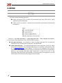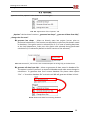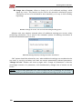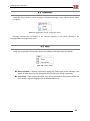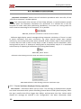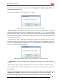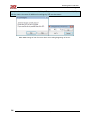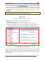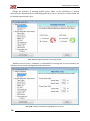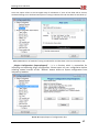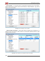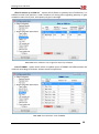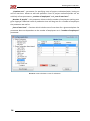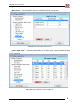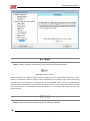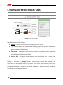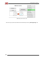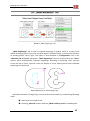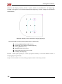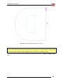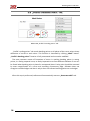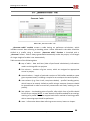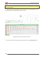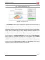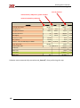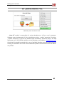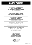
1
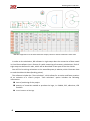
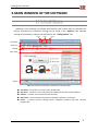
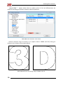
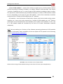
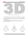
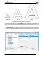
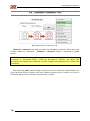
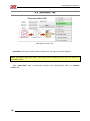
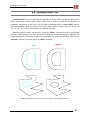
USER GUIDE Publication and distribution only with the consent of: Bending Points Indicator User guide 1. Table of Contents 1. Table of Contents ............................................................................................................................... 2 2. INTRODUCTION .................................................................................................................................. 3 2.1 System Requirements ............................................................................................................. 3 2.2 Software’s Application ............................................................................................................ 4 2.3 Software’s Description ............................................................................................................ 5 3. MAIN WINDOW OF THE SOFTWARE .................................................................................................. 7 3.1 Software’s Window ................................................................................................................. 7 4. MENU ................................................................................................................................................. 8 4.1 File ........................................................................................................................................... 8 4.2 Options .................................................................................................................................... 9 4.3 Language ............................................................................................................................... 11 4.4 Help ....................................................................................................................................... 11 4.5 Automatic Calculations.......................................................................................................... 12 4.5.1 Control windows displayed during operation ............................................................... 12 4.6 Configuration ......................................................................................................................... 15 4.7 Reset ...................................................................................................................................... 26 4.8 Close ...................................................................................................................................... 26 4.9 Transparency „P” ................................................................................................................... 27 5. SOFTWARE’S FUNCTIONAL TABS ..................................................................................................... 28 5.1 „Into Curves” Tab .................................................................................................................. 28 5.2 „Thickness + Clearance” Tab ................................................................................................. 30 5.3 „Save Data” Tab..................................................................................................................... 32 5.4 „Internal curves” Tab............................................................................................................. 33 5.5 „Mark Beginnings” Tab .......................................................................................................... 35 5.6 „Profile’s Bending Points” Tab .............................................................................................. 38 5.7 „Generate Table” Tab ............................................................................................................ 39 5.8 „Costs Calculator” Tab ........................................................................................................... 41 5.9 „Save All contents” Tab ......................................................................................................... 43 6. HELP.................................................................................................................................................. 44 6.1 Contact Data: ......................................................................................................................... 45 6.2 Brand and Trademarks: ......................................................................................................... 45 6.3 Usage and Publication: .......................................................................................................... 45 2 TABLE OF CONTENTS SYSTEM REQUIREMENTS Bending Points Indicator User guide 2. INTRODUCTION 2.1 SYSTEM REQUIREMENTS In order to obtain the technical assistance in the field of software’s usage, following requirements must be met: Microsoft Windows 7 32 i 64 bit, Corel Draw X3, Corel Draw X6 32 bit, Corel Draw X6 64 bit. It is assumed for a given package, that the user owns only one version, or decides to use only one version of the above mentioned software. Due to a nature of access to Corel Draw software, during the launching of the Bending Points Indicator software only one version can be running! You cannot switch between Core Draw windows when the software is running, as it might result with errors in the software and achieving incorrect results, or in not-responding of Corel Draw software. It is allowed to use other software when running BPI1 software, under condition, that computer’s capabilities allow for that. Software itself does not have excessive hardware’s requirements. BPI software should work on every computer which can be using Corel Draw X3 or X6 version. It is also possible to use the BPI software on other versions of Windows software, and with the following versions of Corel Draw software: Corel Draw X4, Corel Draw X5. However, in this case 3D SYSTEM Company will not be able to provide technical service on the BPI software. New version of BPI should work in Windows XP but it requires .NET Framework 4.0. We recommend to upgrade your Operating System to Windows 8. BPI may not work in Windows Vista! We recommend tu upgrade your OS to Windows 8. 1 Abbreviated name of the „Bending Points Indicator” software INTRODUCTION SYSTEM REQUIREMENTS 3 Bending Points Indicator User guide 2.2 SOFTWARE’S APPLICATION ”Bending Points Indicator” software was created as an alternative solution against very expensive automatic benders presented on trade shows. Excessive price of mechanical devices has narrowed the number of potential users, that is why 3D SYSTEM Company tried to meet the expectations of smaller companies and created a software that indicates bending points and replaces traditional manual measures with a measuring tape. Introduction of the software proposed by 3D SYSTEM Company into the production process of building spatial signs, reduces the time of production to the similar time as when using special machines. Creation and preparation of a file, machine calibration and launching requires similar amount of time as marking bending points and bending profile. Therefore 3D SYSTEM Company proposed to its client, even those who work with spatial signs rarely, relatively cheap instrument supporting the process of building channel letters. Option of "Cost calculator" is a big asset of the „Bending Points Indicator” software, and it allows for a fast creation of project's costs estimate. "Cost calculator" option allows to calculate the usage of particular materials, with an indication of price and quantity of those materials. "Cost calculator" is a solution for professionals managing the production process. We are planning to introduce a new option in the „Bending Points Indicator” software which will help arrange the led modules in spatial signs. Soon a paid upgrade containing this option will be available. 4 INTRODUCTION SYSTEM REQUIREMENTS Bending Points Indicator User guide 2.3 SOFTWARE’S DESCRIPTION ”Bending Points Indicator” software was designed to indicate bending points on aluminum profiles (3D-Profile, 3D-Edge Profile) and replaces classic measurements with a use of measuring tape. ”Bending Points Indicator” software significantly accelerates the production process of building channel letters, and eliminates errors done by employees who do the measurements of letter's fronts with a measuring tape. Indication of bending points is done directly in the window of the Corel Draw software. Software requires working on a single project on 1 page, or on several projects, each on 1 page. Calculations are done basing only on curves done directly in the Corel Draw software. Curves imported from software other than Corel Draw contain system errors and lead to receiving incorrect data. Changed curves (imported from software other than Corel Draw) have to be created again in Corel Draw software by using “Create new object surrounding marked objects” function. Pict. 2.1. Corel Draw Function „surrounding shapes” Achieved calculations can be saved in a file. Saving data automatically generates additional file with a .sqite extension, which in case of any problems with a calculation has to be sent on the [email protected] e-mail address. This file will help to evaluate and analyze correctness of the calculations. Calculations are documents addressed to professionals dealing with creation of channel letters. All data included in the table should be read according with a principle "from left to right", and that is also how bending points should be marked on aluminum profile. Each line refers to one shape- curve. Columns refer to given values: first – number of the curve second – quantity of profile needed to assemble entire letter, together with an overlap. rest – distance between bending points on aluminum profile Below You will find a preview of the window with data. INTRODUCTION SOFTWARE’S DESCRIPTION 5 Bending Points Indicator User guide Pict. 2.2. Appearance of the basic table with shapes, based on which calculations were done In order to do calculations, BPI software in eight steps does the conversion of data saved in Corel Draw software into a format of a table containing all necessary calculations. Each of eight steps can be found in tabs, which will be described in later part of the User Guide. You will find a training animation on the www.3dsystem.pl website, which illustrates how to read the table with data (bending points). The software includes the "Cost calculator", which allows for an easier and faster creation of an estimate of a client's project. "Cost calculator" option includes the following information: time of producing of the project quantity of materials needed to produce the logo, i.e. PMMA, PVC, adhesives, LED modules cost of creation of the logo 6 INTRODUCTION SYSTEM REQUIREMENTS Bending Points Indicator User guide 3. MAIN WINDOW OF THE SOFTWARE 3.1 SOFTWARE’S WINDOW Software's main window is provided with function tabs, which allow to calculate the project. Parameters of software's settings can be found in the "Options" tab, whereas settings of calculation's indictors can be found in the "Configuration" tab. version edition engine actual DB top menu toolbar tabs’ field footer Pict. 3.1. Division of software’s window for functional tabs actual DB – short path of currently open database file; top menu – software’s menu which contains additional functions of the software; toolbar – contains most commonly used functions; tabs’ field – contains buttons and options allowing to perform calculations; footer – contains system’s closing button, navigation between tabs and universal progress bar. MAIN WINDOW OF THE SOFTWARE SOFTWARE’S WINDOW 7 Bending Points Indicator User guide 4. MENU 4.1 FILE "File" tab contains following functions: import and export files, on which the calculation was done (files with a .sqlite extension), to the data base, "show current corrections"- preview of set corrections' parameters of performed calculations. Pict. 4.1. Appearance of the File tab Functions: "use other data base", "export data base file", "show current corrections" are used by the help department of the 3D SYSTEM Company. Use other data base – this function is used to change data base file, on which the calculation using “Bending Points Indicator” was performed. Export data base file – is a record of software's entire data base into a file, which has to be sent together with a detailed description of a problem, and name of a file on a [email protected] e-mail address, in case of any problems with project's calculations. Help department will check the correctness of performed calculations, based on the received data base with saved files. In case of an error in the calculation, help department will estimate, or find the cause of irregularities, and will inform about circumstances of arising the incorrect data. 8 MENU SYSTEM REQUIREMENTS Bending Points Indicator User guide 4.2 OPTIONS Appearance of the „Options” tab is shown on the Drawing 6.1. Pict. 4.2. Appearance of the “Options” tab „Options” tab has three functions: „generate last shape”, „generate all data from SQL”, „change size of arrows”. generate last shape – allows to directly open last project (curves prior to performed calculations). This function can be used to re-perform calculations saved in data base, if the given option is selected (Pict. 6.2). In case of sending data base to the help department, make sure this option was selected during performed calculations (it is selected by default in the full version of the software). Pict. 4.3. Conversion „into curves” with a selected option of saving copy in the data base generate all data from SQL – allows to generate all data stored in database file. This option is useful if you wan’t to import old database and make some changes in calculations. To generate data from custom database file please select option “File” “Use other database file” and wait until BPI will generate all data in Corel. Pict. 4.4. Generate data from existing database MENU OPTIONS 9 Bending Points Indicator User guide change size of arrows– allows to change size of all additional markings, which appear by curves. This function can be used in the automatic calculations (pauses calculations and rest of work should be done manually), or in step 4, while marking beginnings. Pict. 4.5. Change of arrows’ size and cells describing bending points. Software asks user whether entered values of additional markings are correct, when performing calculations. This is one of free automatic options of checking correctness of performed calculations (see Pict. 6.4). Pict. 4.6. Message displayed during automatic calculations “NO” option should be selected by user, when additional markings are considered to be too small, or too big, and when user does not accept automatically selected parameters. “Change cell size” window will show up again then. Change of parameters is done by percentage increase of a parameter, and simultaneously changes size of arrows on the screen. Example: If we increase parameter of a value of 109,58 by 50% (parameter will increase to value of 164,37), we will also observe increase of additional markings by 50% on the screen. 10 MENU SYSTEM REQUIREMENTS Bending Points Indicator User guide 4.3 LANGUAGE “Language” menu allows to select language of displayed messages in the software (either Polish or English). Pict. 4.7. Appearance of the “Language” menu Language selected after installation of the software depends on the values selected in the language field of the registration form. 4.4 HELP “Help” menu provides information about the software and download User Guide. Pict. 4.8. “Help” menu About software – displays information about the held license of the software, and allows to read license terms acceptable for the end-user during installation. User Guide – after clicking this field, user will be directed to the website where the User Guide in a given language can be downloaded from. MENU LANGUAGE 11 Bending Points Indicator User guide 4.5 AUTOMATIC CALCULATIONS „Automatic calculations” button starts all calculation procedures with a one click, till the „save file on computer” window appears. NOTE: User cannot open other versions of Corel Draw software, or switch between opened windows when the automatic calculations are performed. It is advised not to use the computer for other tasks while performing calculations, or at least not running tasks too much resource-consuming for the computer, if it is possible. Pict. 4.9. „Automatic calculations” button from the toolbar Software might display control messages during automatic calculations. If there is a need to pause calculation and enter corrections, e.g. when internal shapes were marked incorrectly, rest of steps have to be taken manually. Order of taken steps is clearly defined. It means that You have to take all next steps in order to obtain correct calculations, when coming back to step no. 3. Attempt of coming back to steps before step no. 3 is associated with necessity of repeating all calculations (by clicking Reset button). Pict. 4.10. „Reset” button Software’s tabs showing successive steps are shown on Picture 9.3. Pict. 4.11. Software’s tabs showing successive calculation steps. 4.5.1 Control windows displayed during operation First control – information about size of curves. This message is displayed when project has values inconsistent with system of building channel letters of 3D System company- when the sign is smaller than 35cm, bigger than 200cm, and narrower than 3cm. Values which display this message are entered in the “configuration” tab. More information about 12 MENU SYSTEM REQUIREMENTS Bending Points Indicator User guide parameters can be found in the description of “configuration”, “global configuration” and “curves maximum size” tabs. Ignoring the message is done by selecting „NO” option. Pict. 4.12. Message about incorrect size of one of shapes. Second control – information about correctness of shape’s markings, which are placed inside second curve (those curves are marked in blue), e.g. letter “b”, “e”, or any other shape consisting of two curves, where one component is placed inside another one. Information about correctness of shape’s markings plays a key role in application of correct amendments to software’s calculations. Correctness of curves’ markings automatically given by the software must be strictly controlled. In case of marking curves incorrectly, calculation has to be stopped, corrections have to be applied manually, and mark „NO” in control window. If automatic markings are correct, mark “YES” in control window. Pict. 4.13. Message confirming that internal shapes are marked correctly Third control – information about size of additional markings, given by the software in order to: - define beginning point, where wrapping letter’s face with „3D-Profile” should be started; - show bending points, by allocating green and red squares in places where „3D-Profile” should be bent. If automatic markings of curves are too small, or too big, „NO” option should be chosen, and “change size of squares” window will show up automatically. Change of parameter’s size is done by percentage change of a parameter and changes size of arrows simultaneously. MENU AUTOMATIC CALCULATIONS 13 Bending Points Indicator User guide Example: If we increase parameter 109,58 by 50% (we will increase its value into 164,37) we will also notice increase of additional markings by 50% on the screen. Pict. 4.14. Change of size of arrows which are marking beginnings of curves. 14 MENU SYSTEM REQUIREMENTS Bending Points Indicator User guide 4.6 CONFIGURATION „Configuration” menu is used to set software’s parameters and parameters of “Costs calculator”. NOTE: Changes are done by double-clicking the lettering, which is then modified. Currency is applied pictorially for future development of the software’s functions. Pict. 4.15. „Configuration” button from the toolbar. Window of software’s configuration (Pict. 10.2) can be divided into 3 parts: Options tree – in this part user selects software’s options; Software’s configuration field – in this part user changes software’s configuration; footer – Save changes button saves only global changes, i.e. changes referring to entire configuration field, apart from „costs calculator” (configuration of additional materials). Option tree area Configuration area Footer area Pict. 4.16. Software’s configuration window. Picture 10.2 shows the window of changes of global configuration. When software is working properly, those changes should not be modified. Changes can be done only for the duration of software’s work. This configuration should be reset to the default settings after another restarting. Notwithstanding handling options can be done only after consulting it with the help department of 3D System Company. MENU CONFIGURATION 15 Bending Points Indicator User guide Change the direction of bending profile option allows to do calculations in reverse direction than advised direction of bending profile (Pict. 10.3.) - direction in which profile will be wound around letter’s face. Pict. 4.17. Change of direction of bending profile. „Maximal size of curves” parameter is responsible for limiting size of curves (letters) the software has to control during performed calculations. Pict. 4.18. Change of limitations regarding size of curves. 16 MENU SYSTEM REQUIREMENTS Bending Points Indicator User guide Auto save option refers to the last eighth step of calculations. If none of the fields will be chosen, window allowing to set the destination place of saving CorelDraw file and data base file will show up. Pict. 4.19. Selection of method of saving CorelDraw file and data base in the last calculation step. „Plugins Configuration (import/export)” – it is a function which is responsible for importing and exporting plugin configuration. Please export all your configuration before installing newest wersion of BPI. “Default” button allows to import configuration from 3dsystem.pl website. Pict. 4.20. Import/Export of configuration data. MENU CONFIGURATION 17 Bending Points Indicator User guide „Cost of profile” – it is a function which is responsible for updating prices of “3d-Profiles”. Allows to add another positions (only numerical data) to “Costs calculator”, e.g. price of 100mm silver mirror profile. Pict. 4.21. Costs calculator: Cost of profile „Glue for letters up to 80cm” – option which allows to update prices of adhesives. It is allowed to add new positions, under condition of setting data regarding quantity of glue needed to make 1m of joint. Pict. 4.22. Costs calculator: Cost of glue for letters up to 80cm. 18 MENU SYSTEM REQUIREMENTS Bending Points Indicator User guide „Glue for letters up to 200 cm” - option which allows to update prices of adhesives. It is allowed to add new positions, under condition of setting data regarding quantity of glue needed to make 1m of joint, and capacity of glue’s cartridge. Pict. 4.23. Costs calculator: Cost of glue for letters up to 200 cm. „Cost of PMMA - option which allows to update prices of PMMA and differentiates the materials according to thickness. Allows to add new positions. Pict. 4.24. Costs calculator: Cost of PMMA. MENU CONFIGURATION 19 Bending Points Indicator User guide „Cost of PVC” ” - option which allows to update prices of PVC and differentiates the materials according to thickness. Allows to add new positions. Pict. 4.25. Costs calculator: Cost of PVC. Software calculates usage of materials in m² (square meters- PMMA and PVC) basing on maximal size of shapes (see example below). Pict. 4.26. Method of calculating usage of PMMA and PVC. 20 MENU SYSTEM REQUIREMENTS Bending Points Indicator User guide „Costs of LED modules” – option which allows to update prices of LED modules. Defines position according to number of diodes in a module. Allows to add new data. Last column „number of modules per 1m² is a rate of usage of LED modules according to letter’s surface. This parameter needs calculation (by workshop attempts) of number of LED modules needed for 1m², depending on the color of given LED modules. Value of the calculation should be entered into the “number of LED modules per 1m²” position. LED modules – one of elements of illumination system, which also includes wiring, power suppliers, etc., that is why value entered into “number of LED modules per 1m²” position should be a sum of all illumination costs divided by the number of LED modules. In sum- cost of 1 LED module should be increased by the cost of all other illumination materials adequately. NOTE: We are working on a function of the software presenting placement of LED modules in letters. Information about availability of the new option will be posted on the following website: www.3dsystem.pl/program Pict. 4.27. Costs calculator: Cost of LED modules Software shows usage of LED modules basing on the surface of letters (see example below). MENU CONFIGURATION 21 Bending Points Indicator User guide Pict. 4.28. Method of calculating usage of LED modules. „Time of realization” – parameter which defines time of producing letters and affects costs of labour force depending on the difficulty of creation of letters. Allows to add new positions. Calculation of production time bases on two main functions: “level of difficulty” and “Productivity factor”. „Level of difficulty” parameter is responsible for change of production time, or cost of labour, and is expressed 0-100% percentage scale. Modifications include percentage graduation (see picture below). przykładowa skala trudności w wykonaniu liter 0% 22 50% MENU SYSTEM REQUIREMENTS 100% Bending Points Indicator User guide 100% 50% 0% Pict. 4.29. Sample level of difficulty in producing letters. Increase of percentage value of f „level of difficulty” factor increases time of production and labour costs at the same time. Controlling this parameter should take place only in case of new calculations. “Productivity factor” was set after analyzing many projects, which is why it is not advised to update it. Change of this parameter results in substantial modifications in calculations and distorts realness of calculations. Pict. 4.30. Costs calculator: Estimated time of producing a letter. MENU CONFIGURATION 23 Bending Points Indicator User guide „Creation cost” - parameter for specifying costs of project realization/order, basing on cost of man-hour. Allows to add new positions. Costs of project realization/order are set with help of two parameters: „number of employees” and „cost of man-hour”. „Number of people” – this parameter allows to define number of employees working on a given logotype. Obtained result of production time will be given for a number of employees the parameter was set for. „Cost of man-hour” – function which includes cost of man-hour for a given workplace. Set parameter does not dependent on the number of employees set in “number of employees” parameter. Pict. 4.31. Costs calculator: Costs of realization. 24 MENU SYSTEM REQUIREMENTS Bending Points Indicator User guide „CNC Cut cost” – function which allows to include Plexi/PVC cutting cost. Pict. 4.32. Costs calculator: CNC Cut Cost. „Power supply cost” – function which allows to calculate power supply needed to power all LED modules. Pict. 4.33. Costs calculator: Power supply cost. MENU CONFIGURATION 25 Bending Points Indicator User guide Pict. 4.34. Power supply cost: percent value added to calculated value. 4.7 RESET „Reset” button– function of returning to the project prior the calculations. Pict. 4.35. „Reset” button. When achieved result is different than in case of original (e.g. only curves/outlines are left), „undo” option of CorelDraw software might be used. Remember that undoing steps while performing calculations can have disastrous consequences for the achieved results. Lack of synchronization between data from data base and data from software can occur. That is why reset button must be used consciously. It is recommended while moving back, to select prior tab in the software and repeat the step. 4.8 CLOSE „Close” button is used to close Bending Points Indicator software. 26 MENU SYSTEM REQUIREMENTS Bending Points Indicator User guide Pict. 4.36. ”Close” button The „X” button from software’s window was blocked due to internal security of the software, and because of saving data concerning placement of the window before closing. 4.9 TRANSPARENCY „P” „P” button is used to set transparency of software’s window. When this function is turned on software’s window is active and executing commands is possible Pict. 4.37. „P” button and navigation buttons. Additional navigation buttons are used to navigate between given calculation steps. MENU TRANSPARENCY „P” 27 Bending Points Indicator User guide 5. SOFTWARE’S FUNCTIONAL TABS 5.1 „INTO CURVES” TAB Pict. 5.1. „Into curves” tab. Tab’s field consists of four options: Change – launches mechanism of changing shapes into curves; „?” – works only after the mechanism of changing shapes into curves is finished and allows to locate curve, which is too small, or too big. In order to do so we mark the given curve and click the button; Save to SQL – if this option was selected, mechanism of changing shapes into curves will take more time, but it will be available to recreate generated shape in future by clicking OptionsGenerate last shape; Save to CDR – this option allows to return to original shape prior to change into curves. When this option is not selected, reset cannot be done! „Into curves” option converts projects into set of curved lines and rejects color fill. This function is activated by „Change” button. When curves change their size after the conversion, it is an indication of errors in curves. Errors occur when importing curves from software other than CorelDraw. In such case, curves imported from software other than CorelDraw should be re-created in CorelDraw software by choosing “Create new object surrounding marked objects” function. 28 SOFTWARE’S FUNCTIONAL TABS SYSTEM REQUIREMENTS Bending Points Indicator User guide krzywe wyjściowe krzywe prawidłowo przekształcone przez program krzywe nie prawidłowo przekształcone Pict. 5.2. Examples of possible changes done by the software. Given option allows for a fast conversion of curves imported from other software into curves saved from foundations by CorelDraw. All objects must be separated before launching this option. Pict. 5.3 “Create new object surrounding marked objects” CorelDraw function. When there are no irregularities apart from project’s centering on a computer screen after „change into curves” step is performed, step 2 „Thickness+Clearance” should be performed. NOTE: „Save to SQL” option cannot be marked off, because given function in case of irregularities allows to return to a project’s copy and creates file with data, which in case of problems, should be sent to the help department of 3D System company. „Save to CDR” option allows to use „Reset” button. SOFTWARE’S FUNCTIONAL TABS „INTO CURVES” TAB 29 Bending Points Indicator User guide 5.2 „THICKNESS + CLEARANCE” TAB Pict. 5.4.”Thickness + Clearance” tab. „Thickness + Clearance” tab adds an outline for calculation purposes, which takes into account widths of „3D-Profies”. „Thickness + Clearance” option is activated by „Add” button. NOTE: 0,60mm value should not be changed, because it is closely correlated with entering corrections in „corrections editor”, which can be found in “Options” tab. When new corrections are created, this parameter must be changed into appropriate to created new corrections. After launching „Add” option change of project into mirror reflection is performed on the screen and new shape is placed in red color (outline of given curves in zoom). It is circuit of 3D-Profile. Below correct software’s performance is shown. 30 SOFTWARE’S FUNCTIONAL TABS SYSTEM REQUIREMENTS Bending Points Indicator User guide Pict. 5.5. Original curve and outline. When there are no irregularities after „Thickness + Clearance” step is performed, next step „Save data” should be performed (2.5). This action will be performed automatically by the software. NOTE: Returning to step 1 from the step 2 cannot be performer. The only option available is to return to the beginning of the project by clicking „Reset” button. SOFTWARE’S FUNCTIONAL TABS „THICKNESS + CLEARANCE” TAB 31 Bending Points Indicator User guide 5.3 „SAVE DATA” TAB Pict. 5.6.”Save data” tab. „Save data” tab saves all information in data base. This step cannot be skipped. NOTE: All further steps from step 3 until step 8 can be undone only to step 2.5, that is to „save data” step. After „Sava data” step is performed, software will automatically move to „Internal curves” tab. 32 SOFTWARE’S FUNCTIONAL TABS SYSTEM REQUIREMENTS Bending Points Indicator User guide 5.4 „INTERNAL CURVES” TAB „Internal curves” tab is responsible for selection of curves, which are placed inside other curve, and marks internal curves with a blue color in order to check the correctness of automatic assignment by the user. This function is launched with an „Auto. Mark” button, which automatically does the selection of curves. Given option is used in case of letters like “O”, “P”, “B”, etc., and in case of other non-standard shapes. Marking internal curves manually by choosing „Mark” function should be performed when the software does not mark all curves inside other curve automatically. Software will assign appropriate corrections and data for calculations to curves marked with a blue color. “Unmark” function is reverse option to “Mark” function. OK Dobrze WRONG źle Pict. 5.7. Samples of correctly and incorrectly marked internal curves. SOFTWARE’S FUNCTIONAL TABS „INTERNAL CURVES” TAB 33 Bending Points Indicator User guide Pict. 5.8. „Internal curves” tab. After this step is performed, software will automatically move to „Mark beginnings” tab. 34 SOFTWARE’S FUNCTIONAL TABS SYSTEM REQUIREMENTS Bending Points Indicator User guide 5.5 „MARK BEGINNINGS” TAB Pict. 5.9. „Mark beginnings” tab. „Mark beginnings” tab is used to indicate beginning of profile, which is a place, from which winding of letter’s face with a profile begins. Software allows to choose the direction of winding profile- left or right. This option is also available in “Configuration” tab, in the “Maximal size of curves” parameter. “Mark beginnings” function is launched by the “Auto” button, which automatically indicates beginnings according to following rules: external curves on top of curve, internal curves on bottom of curve. Below picture with indicated beginnings can be found. Pict. 5.10. Sample of marked beginnings. Individual indication of beginnings can be performed manually by undertaking following steps: marking of corrected curves; choosing „Manual” button with the „Show auxiliary circles” marked option. SOFTWARE’S FUNCTIONAL TABS „MARK BEGINNINGS” TAB 35 Bending Points Indicator User guide Software will display auxiliary circles in places which are considered to be beginnings. Clicking on the given circle indicates appropriate beginning. Further changes are performed automatically. Pict. 5.11. Auxiliary circles visible when changing beginnings. Second method of manually marking beginnings can be done by: marking „Show auxiliary circles” option; selection of a curve with a modified beginning; clicking „Manual” button; displaying nodes of the curve; clicking the point of the curve’s node; indicating new beginning. Because of small points (nodes) of a curve (see picture below) it is the most difficult variant of changing beginnings manually. Project can be zoomed in or out by clicking computer mouse circle during rotation. 36 SOFTWARE’S FUNCTIONAL TABS SYSTEM REQUIREMENTS Bending Points Indicator User guide Pict. 5.12. Real distribution of points on a curve. NOTE: Beginning on a curve can be indicated only on the place of a node. Setting additional node in the project before performing calculations might not succeed, because the software has a set function of eliminating needless points, especially on straight sections. After this step is performed, software will automatically move to „Profile’s ending points” tab. SOFTWARE’S FUNCTIONAL TABS „MARK BEGINNINGS” TAB 37 Bending Points Indicator User guide 5.6 „PROFILE’S BENDING POINTS” TAB Pict. 5.13. „Profile’s bending points” tab. „Profile’s ending points” tab marks bending points on all places of the curve, where sharp deflection of curves to each other. This function is launched by clicking „Mark” button. „Profile’s bending points” function is fully automated and cannot be modified. The most common reason of formation of errors in marking bending points in wrong points, is a faulty prepared curve, or faulty imported curve from different software. Error can be found when bending point is placed in unexpected place. Faulty point should be removed by exact magnification of a curve and rounding unnecessary edge. Software does not recognize rounded edges and that is why it does not indicate bending points on such edges. After this step is performed, software will automatically move to „Generate table” tab. 38 SOFTWARE’S FUNCTIONAL TABS SYSTEM REQUIREMENTS Bending Points Indicator User guide 5.7 „GENERATE TABLE” TAB Pict. 5.14. „Generate table” tab. „Generate table” module creates a table basing on performer calculations, which includes numeric data referring to bending points. Values indicated in the table should be shifted to a profile using a measure. „Generate table” function is launched with a „Generate” button. Table is always generated automatically under the project, in full-length of a logo. Height of a table is set automatically. Table consists of the following data: top of table – date and hour (date of performed calculations); information used in archiving offers or projects first column – numbers of given curves, which are assigned to appropriate curves in project; second column – length of particular sections of 3D-Profiles needed to create given separate letters, including a surplus for an overlap at the end of profile; next columns (e.g. from 1 to 6; see picture below) – profile’s bending points, which have to be exactly shifted to profile using a measure (measure should be immobilized in order to avoid any movements and faulty marking on the profile); last column – last bending point of profile, after which 2cm of profile should be left for an overlap (NOTE: In case absence of profile needed for an overlap, marking of a profile should be stopped and classic method of marking profile with a measuring tape should be performer rows – information about data referring to next curves, letters or shapes. SOFTWARE’S FUNCTIONAL TABS „GENERATE TABLE” TAB 39 Bending Points Indicator User guide NOTE: Points where profile should not be filed with metal file are marked in red color. Points where profile should not be filed should be marked on profile differently in order to avoid erroneous filing. Training animation can be found on 3D System’s website, in the Building letters” tab. It shows the method of shifting bending points on a profile. Pict. 5.15. Sample table obtained during calculations. After this step is performed, software will automatically move to „Costs calculator” tab. 40 SOFTWARE’S FUNCTIONAL TABS SYSTEM REQUIREMENTS Bending Points Indicator User guide 5.8 „COSTS CALCULATOR” TAB Pict. 5.16. „Costs calculator” tab. „Costs calculator” module allows to create project’s estimate basing on entered prices of materials, cost of man-hour, and number of people. This option also estimates time of realization of a project. „Costs calculator” function is launched with a “Start calculations” button. Software automatically performs calculations and generates the table with costs (see picture below). Correct results are obtained only in case of updating appropriate parameters in the “Configuration” tab, from the “Auxiliaries Configuration” tree each time. Given parameters are part of the end result in the “Costs calculator” tab. Parameters of “Costs calculator” can be modified. In order to make corrections, step 7 “Costs calculator” should be re-performed, correct parameters in “Auxiliaries Configuration”, and again click the “Start calculations” button. Software will re-calculate costs basing on a new parameters from “Auxiliaries Configuration”. “Save all” option should be selected after performing calculations. The table contains information about quantity of materials needed for a project’s realization, costs of labour and estimated time of production. Below explanation of 2 examples can be found (“Glue for letters up to 200cm” and “LED modules”), which illustrate distribution of data in the table and calculation of used materials. SOFTWARE’S FUNCTIONAL TABS „COSTS CALCULATOR” TAB 41 Bending Points Indicator User guide Cost of material used material / LED power / power needed material needed for production Price calculation 2014-06-16 13:46 Profil-3D szer. 80mm 30,69m -- 383,91 PLN 77ml 77ml 8,61 PLN 205ml 205ml 26,39 PLN Klej Monolith 342-1 2x 473ml 392,00 PLN Klej Scigrip 2x 410ml 270,00 PLN Klej płynny nr 1 Klej gęsty Plex-9021 Plexi 4 mm + folia 6,18m² -- 6,18 PLN PCV 10 mm 6,18m² -- 6,18 PLN 563x 0,72 W 1 086,59 PLN 30,69m -- 30,69 PLN 9x 486,43 W 442,98 PLN Costs Sum 2 653,53 PLN Make Cost 15,40 PLN 2 668,93 PLN H-80 cm - CITI Led 3W biały LG 8000K cięcie frez 5 mm Zasilacz 60W IP67 Global Sum Make Time 2 p. 5h 7min Software moves automatically to another tab „Save all”, after performing this step. 42 SOFTWARE’S FUNCTIONAL TABS SYSTEM REQUIREMENTS Bending Points Indicator User guide 5.9 „SAVE ALL CONTENTS” TAB Pict. 5.17. „Save all contents” tab. „Save all” module is responsible for saving calculations to a file on user’s computer. Software saves simultaneously 2 files, including one with a „.squilte” extension. File with a „.squilte” extension, in case of any problems with calculations, should be sent to the help department of a 3D SYSTEM company on the following e-mail address: [email protected]. Calculation file should be packed with a use of available Windows archiving software before sending. 3D SYSTEM’s mail server will automatically delete the document from the inbox if not packed. SOFTWARE’S FUNCTIONAL TABS „SAVE ALL CONTENTS” TAB 43 Bending Points Indicator User guide 6. HELP Help support of the software is available only for following CorelDraw versions: X3 and X6. Notes on the encountered problems with the software, or the calculations, should be sent on the following e-mail address [email protected], with an exact description of the irregularities. Help department will answer e-mails as soon as possible. In case of problems which can be solved by the User Guide, e-mails will not be answered. 3D System Company is open for any suggestions regarding improving the software. 3D System employees will carefully consider proposed suggestions and decide about introducing them in the new version of the software. 3D System Company invites to acquainting with a training animation on the www.3dsystem.pl website, in the “Building letters” tab. 44 HELP SYSTEM REQUIREMENTS Bending Points Indicator User guide 6.1 CONTACT DATA: 3D SYSTEM ul. Środkowa 7, Opacz Kolonia 05-816 Michałowice k/Warszawy NIP: 812-119-42-66 tel. +48 22 350 71 12; +48 22 350 71 11. [email protected] 6.2 BRAND AND TRADEMARKS: Is a registered trademark and cannot be used without consent of 3D System company in any pulbications, folders, etc. 6.3 USAGE AND PUBLICATION: The instruction is an intellectual property of 3D System company, and can be distributed and published in electronic media, and in a paper form only in courtesy of 3D System company. HELP CONTACT DATA: 45