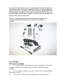
1
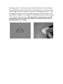
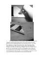
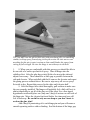
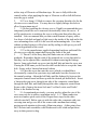
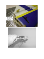
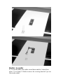
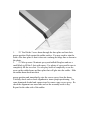
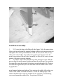
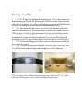
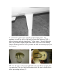
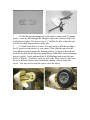
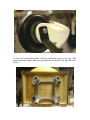
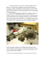
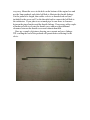
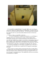
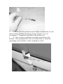
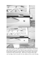
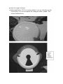
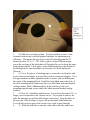
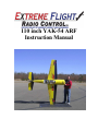
110 inch YAK-54 ARF
Instruction Manual
©Copyright 2008 Extreme Flight RC, Ltd.
Please take a few moments to read this instruction manual before
beginning assembly. We have outlined a fast, clear and easy method to
assemble this aircraft and familiarizing yourself with this process will
aid in a quick, easy build.
Please read the following paragraph before
beginning assembly of your aircraft!
THIS IS NOT A TOY! Serious injury, destruction of property, or even
death may result from the misuse of this product. Extreme Flight RC is
providing you, the buyer with a very high quality model aircraft
component kit, from which you, the buyer, will assemble a flying model.
However it is beyond our control to monitor the finished aircraft you
produce. Extreme Flight RC will in no way accept or assume
responsibility or liability for damages resulting from the use of this user
assembled product. This aircraft should be flown in accordance to the
AMA safety code. It is highly recommended that you join the Academy
of Model Aeronautics in order to be properly insured, and to operate
your model at AMA sanctioned flying fields only. If you are not willing
to accept ALL liability for the use of this product, please return it to the
place of purchase immediately.
Extreme Flight RC, Ltd. guarantees this kit to be free of defects in
materials and workmanship for a period of 90 days from the date of
purchase. All warranty claims must be accompanied by the original
dated receipt. This warranty is extended to the original purchaser of
the aircraft kit only. Please inspect the model immediately upon receipt.
Extreme Flight RC in no way warranties its aircraft against flutter. We
have put these aircraft through the most grueling flight tests imaginable
and have not experienced any control surface flutter. Proper servo
selection and linkage setup is absolutely essential. Inadequate servos or
improper linkage set up may result in flutter and possibly the complete
destruction of your aircraft. If you are not experienced in this type of
linkage set-up or have questions regarding servo choices, please contact
us. It is your responsibility to ensure the airworthiness of your model.
Congratulations on your purchase of the Extreme Flight RC 110 inch
YAK-54 ARF! This new Extreme Flight Yak-54 includes all first rate
hardware and components and thorough instructions to ensure a
trouble free assembly and setup. Weight saving components are used
throughout, such as carbon fiber wing and stab mounting tubes, carbon
fiber main landing gear, titanium pushrods and a carbon fiber tail
wheel assembly, all ensuring the lightest, most high performance
aircraft possible. You will notice there is a box built into the bottom of
the Yak’s fuselage. This is a pipe tunnel and will accommodate the full
range of canister mufflers and tuned pipes sold for the current makes of
100cc class engines. Also included is a set of protective wing and stab
bags and a canopy/hatch cover to keep your investment looking great
season after season. The performance ability of the Extreme Flight RC
Yak-54 is phenomenal! With its low weight and enormous control
surfaces, the Yak-54 is a 3D monster, capable of all current 3D
maneuvers as well as possessing the ability to forge new ground in this
exciting new style of flying. The Yak is also a topnotch precision
aerobatic machine. It is capable of performing the entire FAI catalog of
maneuvers and it has the kind of “40% plane” presence in the air that
will impress the judges. This makes the 110 inch Yak a great candidate
for all classes of IMAC competition. We have spent a great deal of time
and effort to provide you, the discriminating aerobatic enthusiast, with
the highest quality, most complete package possible. We are very proud
of the end result of our labor and wish you great success with the
assembly and flying of your Extreme Flight RC 100cc Yak-54!
A few tips to ensure success and airframe longevity
1.
1. We are very pleased with the level of craftsmanship displayed by the
builders in our factory. Through many grueling test flights containing maneuvers
that no aircraft should be subjected to, our Yak prototypes have remained rigid and
completely airworthy. However, it is impossible for us to inspect every glue joint in
the aircraft. Take a few minutes and apply some medium CA to high stress areas
such as servo mounting trays, landing gear blocks, the intersection of the wing root
rib and wing sheeting, anti rotation pins, etc. A few minutes spent here inspecting
the joints and applying glue where needed is time well spent
2.
2. Having survived the journey half way around the world while
experiencing several climate changes, it is not uncommon for a few wrinkles to
develop in the covering. Fear not! These are not manufacturing defects, and are
easily removed with a little bit of heat. Use a 100% cotton tee-shirt and your heat
gun and heat the covering while gently rubbing the covering onto the wood with the
t-shirt. Be careful not to use too much heat as the covering may shrink too much
and begin to lift at the edges. Take your time, and a beautiful, paint like finish is
attainable. The black covering may require a little bit more attention than other
colors due to its tendency to absorb heat.
3.
3. By the time the Yak arrives at your door step it will have been handled by
a lot of people. Occasionally there are small dings or imperfections on some of the
surfaces. A neat trick to restore these imperfections to original condition is to use a
very fine tipped hypodermic needle to inject a drop of water under the covering
material and into the ding in the wood. Apply heat to the area with a sealing iron
and the imperfection will disappear. Deeper marks may require that this process be
repeated a couple of times to achieve the desired result, but you will be surprised at
how well this technique works.
4.
4. DO NOT SKIMP ON SERVOS! The Yak-54 is equipped with very large
control surfaces that deflect over 45 degrees. A lot of servo power is required to
prevent flutter and to maintain the required deflection for maneuvers. We
absolutely recommend the use of high torque METAL GEAR servos. We have had
great success with the Hitec HS-5955 and now the 7955 servos in our prototypes. We
also recommend the JR 8611A or new 8711 or other 180oz torque or higher for all
flight surfaces. Note: unless using the JR8711 or higher torque servo, you may need
two ganged servos for the rudder to attain 400oz.
5.
5. Use a high quality epoxy for installing the composite control horns and
hinges. We highly recommend the use of Pacer Z-Poxy 30 minute formula. We
have used this glue for many years with zero failures.
Hardware
Your new Extreme Flight 110 inch Yak includes all necessary hardware with the
exception of main wheels, axles and collars. These items were omitted as I have
been unable to source satisfactory versions of these items in China. I recommend
Dubro 3/16” axles and collars and 4.5 or 5 inch main wheels. If you intend to use
the wheel spats I highly recommend that you use a stiff set of wheels versus soft
foam wheels. This will help to prevent the spats from touching the ground and
possibly damaging them.
On the following page is a photo of the various connectors used for the Yak. You
will notice 3 sets of 3mm bolts. The 4 shortest of these (1/2” long) 3mm bolts are
the stab retention bolts which mate up with the pre-installed blind nuts in the rear
of the fuselage. The 2 medium length (5/8”long) 3mm bolts are for securing the
carbon fiber tailwheel assembly (the appropriate blind nuts are already installed
in the bottom rear of the fuselage to accept these bolts). The 4 longest 3mm bolts
are for securing the canopy.
You will find a complete pull-pull system, as well as high quality Dubro heavy
duty ball links, titanium turnbuckle pushrods and composite control horns, and
a carbon fiber tailwheel assembly. You will find a white ball link for use on
your throttle linkage.
The bonded sealing washers are used when mounting the cowl and canopy/hatch.
When the bolts used to retain the canopy/hatch and cowl are tightened against the
bonded sealing washer, the rubber on the washer compresses, preventing the bolt
from backing out. The rubber on the washer also protects the surface of the cowl.
Tighten the bolts until the rubber compresses, but do not allow the metal part of the
washer to make contact with the cowl.
There are 6 titanium pushrods included in the hardware package. The
titanium turnbuckle style pushrods are used for elevator and aileron
actuation.
Let’s Begin!
Elevator Assembly
1.
1. Locate the horizontal stabilizer/elevator assemblies as well as the
composite control horns and base pieces from the elevator hardware
package.
2.
2. Use a sharp #11 blade to open the 2 slots near the bottom leading
edge of the elevator.
3.
3. Insert the 2 control horns into the base plate as shown in the
following picture. Carefully insert the control horns into the slots and push
down until the base plate is flush with the control surface. You may need to
trim the edge of the base plate to prevent it fro overhanging the bevel. Use a
fine tipped felt marker to trace the outline of the base plate and remove the
control horn assembly. Use a sharp #11 hobby blade to remove the covering
1/16” inside the lines you drew. Do not cut into an open bay area or into
the sheeting, cut the covering only. Make your cut only where there is
sheeting below the covering.
1.
4. Use some denatured alcohol to remove any residue or oils from the
composite control horns and base plate. If you wish to paint the control
horns for a more finished appearance now is the time to do so. Use some
fine sandpaper to roughen the portion of the control horns that will be
inserted for gluing. Mix up some 30 minute epoxy (add a little milled
fiberglass if you have it) and using a toothpick or an old #11 blade to force
glue into the slots and make sure they are thoroughly coated with epoxy.
Use an epoxy brush to thoroughly coat both sides of each control horn as
well as the bottom of the base plate. Use an abundance of glue here, as any
excess will be forced out of the slot when you insert the horns.
.5. Insert the horns and push them into the slots until they are seated flush
with the base plate and the base plate is flush with the control surface. Insert
one of the 3mm bolts through the 2 control horns as shown to insure proper
alignment. Use some denatured alcohol and paper towels to remove the
excess glue and inspect the assembly. When satisfied set this assembly aside
to dry. Repeat this process for the other elevator half.
1.
6. Locate 4 hinges per elevator half. There are two hinges that have
one end shorter, these go into the inner two holes of the horizontal such that
they will not interfere with the socket. Be sure the hinges clear the socket
before gluing.
2.
7. In this step I will outline the procedure we use to install the hinges.
There are several ways to do this and several adhesives you can use. We
will describe the way we do it, as this method has proven itself over many
years of model building. If you are new to this type of hinging process then I
recommend that you install a single hinge first just to acquaint yourself with
this method. Before starting the process get a few items together that will aid
you as you proceed. You will need the following items: 30 minute epoxy
(again, we recommend Pacer Z-Poxy), a scrap piece of pushrod, toothpick or
1/8” dowel, paper towels and denatured alcohol. Mix a generous batch of 30
minute epoxy. Use the pushrod or dowel to thoroughly coat the hinge hole
with epoxy, then coat the hinge with epoxy. Push the hinge into its hole until
the joint is about a ¼” from its final position and use a paper towel to
remove the excess epoxy that has been forced from the hole. Push the hinge
the rest of the way in and make sure the hinge pin is centered in the hinge
line. Use some denatured alcohol and a paper towel to remove all excess
epoxy, especially on the hinge pin. When you are satisfied with the result
set the surface aside to dry. Position the drying piece so that any excess
epoxy will pool around the rear of the hinge.
TIP: you may coat the pin section only with petroleum jelly (or something
similar) to keep epoxy from drying in the pin section. Be sure not to coat
anything but the pin (center) section as that would hinder the epoxy from
curing at full strength. Be sure the hinge is not sideways in the hole.
1.
8. When you are comfortable with this process you should be able to
do one side of a surface per batch of epoxy. Glue all hinges into the
stabilizer first. After the glue has set trial fit the elevator to the stab and
adjust if necessary. There should be as little gap as possible between the
stab and elevator. When satisfied with the fit remove the elevator and repeat
the gluing process outlined above. Be sure to wipe away all excess epoxy!
Set aside to dry. Repeat this process for the other stab/elevator half.
9. After the hinges have dried thoroughly, pull on them to make sure
they are properly installed. The hinges will probably feel a little stiff as it is
almost impossible to get all of the glue out of the joint. Use a fine tipped
hypodermic needle and place one (only one!) drop of acetone on each side of
the hinge pin. Move the elevator back and forth a few times and you will
feel it loosen up. Be careful to only use one drop as you don’t want to
weaken the glue joint!
Add a drop of penetrating oil to each hinge pin and you will ensure a
smooth operating surface with no binding. Seal the bottom of the hinge gap
with a strip of Ultracote or Blenderm tape. Be sure to fully deflect the
control surface when applying the tape or Ultracote to allow full deflection
once the gap is sealed.
2.
10. Use a sharp #11 blade to remove the covering from the slot for the
elevator servo control horn. You may have to slightly enlarge this hole to
allow for maximum travel.
3.
11. Before installing the elevator servos, I highly recommend that you
temporarily install the servo arms and electronically center the servos. It
will be much easier to match up the servos at this point than when they are
installed. I also recommend that you thin a small amount of epoxy with a
few drops of alcohol and apply a light coat to the inside of the stab and to the
servo mounting rib as well as to the root rib and mounting tabs. Over time
exhaust residue begins to collect here and by sealing it with epoxy you will
prevent degradation of the wood.
4.
12. Use the manufacturer supplied mounting hardware and install the
elevator servo with the output shaft toward the front of the stab.
5.
13. Thread 2 of the heavy duty ball links onto one of the titanium
pushrods. Remember that the ends of the pushrods are reverse threaded so
that they can be adjusted like a turnbuckle without removing the linkage.
Insert a 3mm socket head cap screw into the ball link and into the servo arm.
If using the SWB arms you will need to drill out the hole to accept the 3mm
bolt. Secure with a 3mm nylon insert locknut.
6.
14. Place the servo arm onto the servo (which you should have
electronically centered in a previous step) and make sure the elevator is in
the neutral position. Adjust the ball links until the linkage fits between the
composite control horns and lines up with the desired pre-drilled hole. Insert
a 3mm socket cap screw, through one side of the composite control horn,
through the ball link, and finally through the other composite control horn.
Secure with a 3mm nylon insert lock nut. Use blue Loctite on all bolts!
Below is the finished set-up.
7.
15. As mentioned previously, you may need to adjust the size of the
servo arm exit slot to achieve maximum travel. A ¼” Drum sander in a
moto-tool makes quick work of this. Repeat these steps for the other
stab/elevator half. Before you set aside the stabs take a moment with your
covering iron and go over all of the seams with a medium heat setting,
paying special attention to the ends of thin trim stripes. At this point clean
the 2 elevator/stab assemblies with Windex and a soft cloth and put them
away in their protective bag.
NOTE: the methods used to install the control horns, servos, hinges and
linkages is virtually the same for the ailerons and to some degree the rudder.
Wing Assembly
1.
16. The assembly process for the wing is almost identical to that of the
stab/elevator. For this reason we will not go into quite as much detail as in
the previous procedure. Remove the aileron from the wing panel. Locate the
4 slots for the control horns and remove the covering from the slots. Follow
the same procedure as outlined previously to install the control horns
into the control surface and hinging the wing. You may need to trim
1/16” from the front of the composite base plate to prevent overhanging the
bevel. Repeat this procedure for the other wing.
2.
17. Locate the aileron servo holes and remove the covering from these
areas. Use a sealing iron to seal the edges of the covering to the insides of
the servo opening. Take a few minutes to apply some CA to the joints of the
servo rails and the ribs.
18. The 110” Yak requires 2 servos per aileron. Use the manufacturer
supplied mounting hardware and install the servos with the output shaft
toward the leading edge of the wing and the servo arm pointing to the wing
root rib.
We used Hitec 5955TG digital servos and used the Hitec digital servo
programmer to ensure that the 2 servos were properly matched and working
together. Then the 2 servos were attached to a Y-Harness and plugged into a
single port in the receiver. The 2 servos in the other wing were set up the
same way and plugged into an auxiliary port in the receiver and the 2
ailerons were connected electronically within the transmitter’s programming
menu.
3.
19. We will fabricate the linkage much in the same way as the
elevator linkage. Aileron control horn length should be 1.50”. As always,
use blue Loctite on ALL bolts!
4.
20. Before beginning the next assembly process, take a few minutes
with your sealing iron on a medium heat setting and go over all seams,
paying special attention to thin trim stripes and the seam at the leading edge
of the wing. If there are wrinkles in the covering on the leading edge
sheeting use a heat gun with a 100% cotton t-shirt to remove them and
prevent digging into the wood with an iron. Use caution and avoid excessive
heat as you may cause the Ultracote to shrink too much and lift at the seams.
Also take the time to seal the hinge gaps with Ultracote or Blenderm tape.
Clean the wings with Windex and put them away in their protective bag.
Rudder Assembly
21. Locate the rudder, the rudder control horns and the 2 slotted base
plates. Use a sharp #11 blade to remove the covering from the 2 pre-cut
slots in the rudder.
1.
22. Trial fit the 2 servo horns through the base plate and into their
proper position flush against the rudder surface. You may need to trim the
front of the base plate so that it does not overhang the hinge line as shown in
the photo.
2.
23. Mix up some 30 minute epoxy and milled fiberglass and use a
small blade to fill the 2 slots with epoxy. Use plenty of epoxy and be sure to
completely fill the two slots. Use an epoxy brush to completely cover the
areas on the rudder horns and base plate that will glue into the rudder. Slide
the rudder horns back into their
proper position and immediately wipe the excess epoxy from the horns.
Carefully check and re-check alignment to insure proper positioning. Use
some denatured alcohol and a paper towel to remove any excess epoxy. Recheck the alignment one more time and set the assembly aside to dry.
Repeat for the other side of the rudder.
Tail Wheel assembly
1.
24. Locate the bag with all the tail wheel parts. Take the main carbon
fiber gear leg and mount the support bushing with the nylon insert nut on top
and tighten. The metal portion that the wheel fits onto, locate that, the top
tiller and 1 wheel collar. You will need to grind some flat spots onto the
metal wire portion of the tail wheel assembly, to allow all set screws to mate
against a flat spot to prevent slippage.
2.
25. Slide a wheel collar onto the top of the metal gear. Now slide the
gear up thru the metal support bushing and past the nylon nut. Now position
the main tiller onto the top until it bottoms out and tighten the bolt. Position
the main tiller against the nylon nut and then slide the bottom wheel collar
up against the
metal support bushing and tighten. Now position the rudder tiller in the very
center of the rudder’s bottom and about ¼” from the leading edge of the
rudder. Mark the hole locations and drill for the supplied wood mounting
screws and mount the rudder tiller. See pictures for detail.
26. Feel along the bottom of the aft bottom fuselage area and you will notice
two holes under the covering. Open these holes and position the carbon gear
leg over them and mount with the supplied machine bolts. Now locate the
springs and mount them within each outer hole of the tillers.
18
Fuselage Assembly
1.
27. We’ll begin by installing the landing gear. Locate the carbon fiber
main landing gear. Insert the gear into the slot on the bottom of the fuselage
and center it in the slot. Use the pre-drilled holes as guides and drill through
the plywood landing gear plate and aluminum mounting bracket.
2.
28. The pipe tunnel has a piece of plywood still attached at the front
just below the motor box. It has been laser cut but has some points not cut to
hold it in place. Cut these areas and remove the plywood such that you can
see down the pipe tunnel. Place a washer on one of the longer 4mm
mounting bolts and insert them through the holes you just drilled from the
landing gear side. The preceding pictures show how the bolts will be placed.
3.
29. Secure the landing gear with 4 washers and nylon insert lock nuts
from inside the tunnel.
4.
30. Attach the landing gear fairings with silicon glue. You may want
to scuff the inside of the fairings with sandpaper for better adhesion.
TIP: you may fit these flush with the fuselage, but I left a small 1/16” gap to
allow the landing gear to flex without damaging the fuselage.
31. Locate the 2 wheel spats and 2 plywood mounting plates. Use
sandpaper to scuff the inside of the spat for better glue adhesion. Drill a
hole as shown in each ply plate about ¼” below center. This will allow the
spat to be positioned slightly higher than center to prevent it from making
contact with the ground. Be sure to position the hole fore and aft properly for
tire clearance.
TIP: since the spat is so big and rough fields can wreak havoc on spats, here
is a suggestion. Glue two small carbon strips inside the spat as shown above
before proceeding with step 32.
1.
32. Glue the ply mounting plate to the spats as shown with 30 minute
epoxy. Once dry drill through the fiberglass spat at the location of the hole
in the plywood plate. We chose to use a ½” drill bit for this so that the spat
will fit over the hexagon portion of the axle.
2.
33. Install your choice of axles. You may need to drill the opening in
the CF gear to accept the axe of your choice. Now slide the spat over the
axle and into position against the landing gear leg. Position as desired and
mark the location for the blind nut using the pre-drilled hole in the aluminum
gear as a guide. Center and install the 4-40 blind nuts and secure the spat
with 2 4-40 bolts. Use blue Loctite on ALL bolts. Slide a wheel collar onto
the axles followed by the wheel and finally another collar to retain the
wheel. You may need to trim the spat to clear the wheel.
34. Next let’s install the engine. We have made this process very easy. The
center and offset marks have been scribed into the front of the firewall with
a laser.
1.
35. Most manufacturers will provide a mounting template for their
engines. If you do not have a template, you can measure the distance
between your engine’s mounting holes and determine the center and align
with the lines on the firewall. The line to the right of the center line is the
proper reference point to use at it provides the proper offset to accommodate
for right engine thrust.
2.
36. Use the recommended mounting bolts to mount the engine to the
firewall, we used ¼” 20 thread per inch bolts. You will need to use 1”
standoffs if using the DA-100. These will provide the recommended distance
for the engine/cowling. The actual distance from the face of the firewall to
the front of the engine drive hub should be 7 5/8”. Drill the necessary holes
and mount the engine, in our pictures we used an aftermarket engine mount,
you could also use 1” diameter wooden dowels or aluminum standoffs.
Remove the engine and brush a coat of alcohol thinned epoxy onto the
exterior and interior of the motor box. When dry, mount the motor. Be sure
to use some large washers behind the firewall to better distribute the load.
Again, use blue Loctite on all bolts.
37. Now lets set up the throttle linkage. If you are using a DA-100 this is
very easy. Mount the servo in the hole on the bottom of the engine box and
use the 2mm pushrod, and white ball link to fabricate the throttle linkage.
Cut the pushrod to length, then solder a clevis or threaded rod end (not
included) to the servo end. Use the threaded end to connect the ball link to
the carburetor. If you plan to use a tuned pipe be sure there is clearance
between the pipes/headers and the throttle linkage. If necessary add a couple
of hardwood rails to elevate the throttle servo and provide additional
clearance between the throttle servo and exhaust manifold.
Here are a couple of pictures showing servo mount and servo linkage.
TIP: scuffing the end of the pushrod will permit better soldering for the
clevis.
.38. Assemble the included Dubro 32 oz tank. Make sure to use the gas
conversion stopper and Tygon tubing for all plumbing. Use nylon cable ties
or velcro to secure the tank to the tank tray. The tank should butt up against
the wing tube and. Use some foam rubber under the tank to isolate from
vibration.
.39. Here is where we installed our fuel dot.
2.
40. Once all plumbing is completed and throttle servo and linkage is
installed glue the top of the motor box in place with 30 minute epoxy.
Alternately you may wish to cut the forward part of the motor box cover
away (the part with the laser cut holes to accept the cowl mounting ring) and
glue it in place, while attaching the remaining portion of the box top with
bolts and blind nuts to allow access to the interior of the motor box. Glue the
cowl ring in place at this time, such that the mounting tabs face forward.
.41. If you are planning to use tuned pipes or canisters now is the time to
install them. We will show how to mount the ES Composite’s tuned pipes.
You will
.need to remove covering, measure your pipe and cut the covering where
the exhaust tube will exit. The picture below shows two holes, the aft one is
where the exhaust will exit, the hole between the gear and the aft hole is to
access the pipe’s mounting bracket. This middle hole will be recovered after
the installation is complete.
3.
42. Locate the lite ply mount, there are two of them but we will use
one in this installation. We decided to put the pipe mount just aft of the
center of the pipe. I glued the mount in and used some scrap tri stock for
additional bracing. I also drilled some holes to wrap my fuel tubing around
for a soft mount of the pipes. I weaved thru the holes and around the pipe
creating a sort of sewn effect. There certainly are other ways to secure the
pipes, but this method has worked well for us. Use whatever method works
best for you.
4.
43. Locate the rudder servo tray in the hardware package. Trial fit the
tray to the mounting rails, there is a small key in the aft rail. Locate the two
pieces of balsa tri-stock, cut 4 pieces the width of the tray and glue these to
the rails. This will provide extra gluing surface for the tray. Apply 30
minute epoxy to the
5.
44. Once this assembly has dried install your rudder servo using the
supplied hardware with the output shaft toward the front of the plane. We
recommend the use of the new “mega-torque” standard size servos such as
the Hitec HS- 5955 or the JR 8611A or 8711 for this position. We have
found a single JR8711 is plenty for the rudder, however the JR 8611 or Hitec
5955 will require 2/each.
6.
45. Next let’s install the pull-pull rudder cables. First remove the
covering from the exit slots at the rear of the fuselage as shown.
7.
46. Assemble one end of the linkage by inserting the pull-pull cable
into a crimp, through the hole in the brass pull-pull fitting and back through
the crimp. Loop the cable back through the crimp a second time and crimp
with side cutters.
8.
47. Insert the bare end of the cable into the slot in the rear of the
fuselage and feed it forward through the hole in the former that is positioned
just in front of the slot. Pull the cable forward into the canopy area and make
up the same type of linkage as you did previously. Secure the linkage at both
ends with a 3mm bolt and nylon insert lock nut. Repeat for the other side.
You will want to use a
1.
4.5 inch arm for the pull-pull system. I highly recommend the 4.5 inch
offset arm from SWB Manufacturing. If using “ganged” servos, we
recommend a 3” Straight arm from SWB on the second servo.
2.
48. Here is where we installed our switches on each side of the
fuselage. After opening the hole with a new hobby blade we soaked the
surrounding wood with thin CA before installing the switch.
49. If you plan to use the supplied louver plate in the front of the cowl now
is the time to install it. Remove the lip from the circumference of the louver
plate with a pair of scissors. You will also want to open the louvers in front
of the engine cylinders for adequate cooling. Glue the louver plate in place
from the rear with 30 minute epoxy. Make sure to scuff the inside of the
cowl and edges of the louver plate for better adhesion. Refer to the following
pictures for single and twin
cylinder installations. TIP: For a twin cylinder, I cut one side then use the
cut out piece as a sort of template for cutting the other cylinder. This
assures uniform holes.
1.
50. Slide the cowl into position. You should allow at least 1 inch
clearance between the cowl and spinner backplate for maximum prop
efficiency. This means the rear of the cowl will extend beyond the F1
former by about ⅜” to ½”. TIP: I like to place a strip of Blenderm tape
across the top front of the hatch that will fit under the cowl to keep the paint
from getting scuffed. I also apply a strip of Blenderm across the bottom of
the fuselage in the same location to prevent the cowl from chafing the
Ultracote.
2.
51. Use a few pieces of masking tape to secure the cowl in place and
view it from several angles to insure that you have it properly aligned. Use a
felt tipped marker to make alignment marks to insure you are drilling into
the center of the mounting block. Install the 3mm blind nuts in the back of
the cowl mounting blocks and secure the cowl with 3mm bolts and bonded
sealing washers. Drill 3 additional holes at the location of the cowl
mounting ring tabs and secure with bolts, blind nuts and bonded sealing
washers.
3.
52. Now let’s install the stab/elevators. You will need to attach 36”, or
longer, servo extensions to the elevator servos. (If you plan to remove the
stabs for transport you will need the longer extensions.) Open the holes in
the rear side of the fuselage to expose the pre-mounted 3mm blind nuts.
You will also need to open a hole for the servo leads to pass through.
4.
53. Slide the stab halves onto the carbon fiber stab tube and secure
with a 3mm bolt and washer inserted through the mounting tabs and into the
pre-mounted blind nuts. Make sure to use a drop of blue Loctite on these
bolts.
5.
54. The canopy is retained by the (4) 3mm bolts and bonded sealing
washers. Before flying the Yak run a bead of RC-56 canopy glue all along
the intersection of the canopy and its wood frame, front and back and both
sides. This glue dries clear, is water soluble and is easy to clean up. Allow
to dry overnight.
6.
55. There are 3 gray Depron pieces that make up the hatch floor and
pilot compartment. The following picture shows the layout of those pieces.
Install the middle piece first, this will allow you to access the pilot for
mounting.
7.
56. Use 30 minute epoxy or other suitable adhesive and glue the
middle piece into the canopy. Now install your desired pilot, instrument
panel or your desired cockpit setup. In our case, we used the Extreme Flight
Pilot X for our pilot.
8.
57. To install the Pilot X figure, we use this procedure. Take the tinted
face shield piece and using scissors, cut along the molded line. Cut from the
inside of the tinted piece and proceed slowly to reduce the chance of cracks
during cutting. Now make some starter holes in the face shield and into the
helmet, and use the supplied screws to secure the face shield to the pilot
head. Now mount the Pilot X figure onto the Depron. TIP: we cut a small
hole in the bottom of Pilot X and installed small pieces of lite ply in the base
which allows small wood screws for mounting. The hatch has some areas at
the sides where screws can go up from the bottom and into the installed
plywood. While the Pilot X figure could be glued to the Depron, is not
recommended as vibration may cause problems over time.
9.
58. Now mount your instrument panel. If using the Extreme Flight
panel cut the clear piece along the molded line. Take the paper instrument
panel and remove the backing paper and this exposes the adhesive side.
Attach this paper panel to the back side of the clear panel, then use the
screws and attach to the lite ply panel. The front side of the panel has
simulated instrument dials which are protruded, mount the paper panel to the
opposite side.
10. 59. When you have all your desired cockpit items installed, you may
glue in the remaining two Depron pieces.
11. 60. The wings are retained by inserting the 2 1/4x20 nylon bolts per
side through the holes in the fuselage just behind the wing tube and into the
pre-installed blind nuts in the root rib of the wing. Be careful not to cross
thread the bolts and inspect them periodically to insure thread integrity.
38
This completes the assembly of the 110 inch Yak. As a final step I recommend you clean
the entire aircraft with glass cleaner, then apply a coat of spray-on wax and buff the finish
to a high gloss. My favorite product for this is Eagle One Wet Wax AS-U-DRY,
available in the automotive section of most Wal-Marts, K-marts, Sears, Targets, etc.
People often ask me at trade shows how I get the planes to look so shiny, this is my
secret. You may wish to apply all of your graphics before applying the coat of wax. The
wax helps to protect the covering and paint and makes clean up easy, as oil residue can
simply be wiped away.
Set-up and trimming
Besides basic assembly, this is the most important
part of preparing your airplane for flight. It can also be the most time consuming. Getting
your airplane dialed in is a continuing process that may take several flights to achieve.
We cannot overemphasize the importance of taking the time to do this and you will be
rewarded with a great flying aircraft. The center of gravity (CG) range for the 110” Yak
begins at 7 1/2” from the leading edge of the wing measured at the root (center of the
wing tube) and extends back 1 1/4” from this point. Make your first flights at the front of
the CG range. There is no need to have the Yak excessively tail heavy to perform 3D
maneuvers. At this time you will also want to balance your plane laterally. Add a small
amount of weight to the wingtip to achieve proper lateral balance. As mentioned earlier,
if you are planning to use a tuned exhaust system you may need to vary your battery
location to attain desired CG.
Control surface throws
I highly recommend that you purchase a throw meter that measures in degrees. There are
several units available commercially. These units are a great aid in set-up and definitely
beat the “that looks about right” method. For any type of precision flying, surfaces that
travel equal distances are a must. The following control surface travels are what I use on
my own Yak. These are a good starting point, but are by no means the only way to set up
the Yak. Start here and then adjust to fit your own preferences and style of flying.
Elevator: 8-10 degrees low rate, 15-20% exponential; all you can get high rate, 60-65%
exponential Aileron: 20 degrees low rate, 30-40% exponential; all you can get high rate,
65-70% exponential
Rudder: 20 degrees low rate, 50% exponential; all you can get for high rate,
80-90% exponential.
Again, this is just a starting point. Adjust to your liking.
The Yak exhibits very little coupling in knife edge flight. There is virtually
no
coupling when using the small amount of rudder needed for point rolls or
slow
rolls. When flying slow high alpha knife edge you may experience a small
amount of coupling. Full rudder rate is typically not needed for this
maneuver
and too much may result in excessive coupling. Experiment with your
throws
and CG to find the sweet spot. Save full rate rudder for flat spins. And
speaking of flat spins, the Yak performs the flattest, slowest descending flat
spins I have ever witnessed. The spin is very controllable and is easily exited
by neutralizing the controls and adding power. One of my favorite moves is
to
allow the plane to flat spin down to 10 or fifteen feet from the ground, then
add
power and begin climbing back up still in a spin. Lots of fun and it gets the
heart racing!
The Yak will also perform the most beautiful, round knife edge loops. It has
so
much rudder authority that recovery on the backside of the loop is typically
at
idle! This is an impressive sight to behold.
The Yak is a very axial rolling airplane. Its massive ailerons provide
tremendous control authority in the roll axis, and high alpha rolling
maneuvers
are one of its strong points. This incredible control authority allows you to
start, stop and change direction of roll instantly. The Yak will obey your
every
command.
Please use common sense when flying the 100cc Yak. The Yak’s airframe
is
very robust, but all airplanes have their limits. This is a very large, yet
lightweight aircraft and as such cannot be stressed like smaller aircraft. Full
power Blenders and Walls are definitely not recommended! Take great care
to
prevent over speeding the airplane which could result in flutter and complete
destruction of your Yak. Reserve full power for vertical lines and always
have
the engine at idle when the nose is pointed down. Inspect your plane
thoroughly after each flying session, looking for loose screws, fatigued or
worn
servo gears, sloppy linkages or loose covering. With proper maintenance,
your
Yak will provide you with many seasons of aerobatic excitement. We
sincerely
hope your Yak brings you as much joy and satisfaction as we have
experienced
with ours! Thanks again for your business! See ya at the flying field!