1
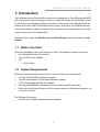
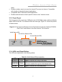
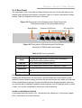
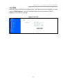
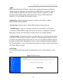
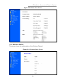
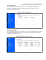
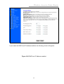
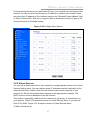
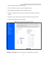
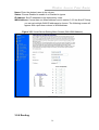
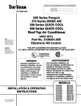
#03075 RP-WR1134
USER’S MANUAL
Wireless Acccess Point Router
Wireless Access Point Router
With Optional PCMCIA Card, Built-in PCMCIA Card,
One Antenna, One Fixed Antenna,
One Reverse SMA Antenna
User Guide
Version 1.3
(PIC)
0
Wireless Acccess Point Router
The information in this guide may change without notice. The manufacturer assumes
no responsibility for any errors which may appear in this guide.
Fast Ethernet is a trademark of XEROX Corporation. Microsoft, Windows and Windows
logo are trademarks of Microsoft Corporation.
Copyright 2002. All right reserved. No Part of the contents of this guide maybe
transmitted or reproduced in any form or by any means without the written permission
of the manufacturer. Printed in Taiwan.
The revision date for this guide is DEC 10th, 2002
Version 1.3
FCC Certifications
You are cautioned that any changes or modifications not expressly approved in this
manual could void your authorization to use the device.
CAUTION: Any changes or modifications not expressly approved by the party
responsible for compliance could void the user’s authority to operate the equipment.
Prohibition of co-location
This device must not be co-located or operating in conjunction with any other antenna
or transmitter.
15.105 Federal Communications Commission (FCC) Requirements, Part 15
This equipment has been tested and found to comply with the limits for a class B digital
device, pursuant to part 15 of the FCC Rules. These limits are designed to provide
reasonable protection against harmful interference in a residential installation.
This equipment generates, uses and can radiate radio frequency energy and, if not
installed and used in accordance with the instructions, may cause harmful interference
to radio communications. However, there is no guarantee that interference will not
occur in a particular installation. If this equipment does cause harmful interference to
radio or television reception, which can be determined by turning the equipment off and
on, the user is encouraged to try to correct the interference by one or more of the
following measures:
---Reorient or relocate the receiving antenna.
---Increase the separation between the equipment and receiver.
---Connect the equipment into an outlet on a circuit different from that to which the
receiver is connected.
---Consult the dealer or an experienced radio/TV technician for help.
1
Wireless Acccess Point Router
Regulatory information / Disclaimers
Installation and use of this Wireless LAN device must be in strict accordance with the
instructions included in the user documentation provided with the product. Any
changes or modifications (including the antennas) made to this device that are not
expressly approved by the manufacturer may void the user’s authority to operate the
equipment. The manufacturer is not responsible for any radio or television interference
caused by unauthorized modification of this device, or the substitution of the
connecting cables and equipment other than manufacturer specified. It is the
responsibility of the user to correct any interference caused by such unauthorized
modification, substitution or attachment. Manufacturer and its authorized resellers or
distributors will assume no liability for any damage or violation of government
regulations arising from failing to comply with these guidelines.
CAUTION: To maintain compliance with FCC’s RF exposure guidelines, this
equipment should be installed and operated with minimum distance 20 cm between
the radiator and your body. Use on the supplied antenna. Unauthorized antenna,
modification, or attachments could damage the transmitter and may violate FCC
regulations.
MPE Statement (Safety Information)
Your device contains a low power transmitter. When device is transmitted it sends out
Radio Frequency (RF) signal.
Safety Information
In order to maintain compliance with the FCC RF exposure guidelines, this equipment
should be installed and operated with minimum distance 20 cm between the radiator
and your body. Use only with supplied antenna. Unauthorized antenna, modification, or
attachments could damage the transmitter and may violate FCC regulations.
2
Wireless Acccess Point Router
Caution Statement of the FCC Radio Frequency Exposure
This Wireless LAN radio device has been evaluated under FCC Bulletin OET 65C and
found compliant to the requirements as set forth in CFR 47 Sections 2.1091, 2.1093,
and 15.247(b)(4) addressing RF Exposure from radio frequency devices. The radiation
output power of this Wireless LAN device is far below the FCC radio frequency
exposure limits. Nevertheless, this device shall be used in such a manner that the
potential for human contact during normal operation—as a mobile or portable device
but use in a body-worn way is strictly prohibit. When using this device, a certain
separation distance between antenna and nearby persons has to be kept to ensure RF
exposure compliance. In order to comply with the RF exposure limits established in the
ANSI C95.1 standards, the distance between the antennas and the user should not be
less than 20 cm.
CE Mark Warning
This is a Class B product. In a domestic environment, this product may cause radio
interference in which case the user may be required to take adequate measures.
3
Wireless Acccess Point Router
Contents
1:
Introduction
1.1 Before You Start
1.2 System Requirement
1.3 How to Use this Guide
2:
Hardware Installation
2.1 Product Description
2.1.1 Overview
2.1.2 Features
2.1.3 Front Panel
2.1.4 LEDs and Reset Button
2.1.5 Rear Panel
2.2 Installing the Router
2.2.1 Preparing for the installation
2.2.2 Getting Started
3:
Configuration
3.1 Configuring the Wireless Access Point Router
3.2 The Setup Wizard
3.2.1 PPPoE Connection for WAN
3.2.2 Fixed IP for WAN
3.2.3 PPTP For WAN
3.2.4 Dynamic IP for WAN
3.2.5 Alias IP Setup
3.2.6 DNS
3.2.7 Wireless Configuration
3.2.8 Time Zone
3.3 Browsing the Status
3.3.1 Status
3.3.2 Wireless Status
3.3.3 DHCP Table
3.3.4 Routing Table
3.3.5 DDNS Status screen
3.4 Viewing the Tools
3.4.1 System Log
3.4.2 Hacker Log
3.4.3 Reset
3.4.4 Upgrade
4
Wireless Acccess Point Router
3.4.5 Backup
3.5 Setup the Advanced Features
3.5.1 LAN IP Setting
3.5.2 DHCP Setting
3.5.3 Firewall Setting
3.5.4 Privilege
3.5.5 Virtual Servers
3.5.6 Routing
3.5.7 WAN MAC Address Clone
3.5.8 DDNS Setting
3.5.9 MAC Control
3.6 Configuring your PCs to Connect to the Router
4:
Specifications
4.1 Technical Specifications
4.2 Environmental Information
4.3 Standard Conformance
4.4 Cable Specifications
Appendix
A: About Static and Dynamic IP Address
B: Comparison Table of Wireless Access Point Routers
C: Warranty Statement
5
Wireless Acccess Point Router
1: Introduction
The Wireless Access Point Router combines the technology of Fast Ethernet and IEEE
802.11b Wireless LAN, providing the home or small office users the Cable/DSL access
to the Internet via cord and cordless connection. At the same time, integrated with the
firewall and 128-bit WEP (Wired Equivalent Privacy) Encryption, the Wireless Access
Point Router allows multiple users to share one Internet connection while ensuring the
safety and security of the packet flow.
Throughout this guide, the Wireless Access Point Router may be referred to as the
Router.
1.1 Before You Start
Check the package of the router before you start. The package contents come with:
One Wireless Access Point Router
One AC/DC Power Adapter
CD
- User Guide
1.2 System Requirement
Before you getting started, make sure you meet the following requirements.
One RJ-45 Cable/DSL network connection
One PC with installed 10/100 Mbps Ethernet Adapter
UTP network cable with RJ-45 connector
Windows 95/98/2000 or Windows NT for the Web-based Configuration
Either Microsoft Internet Explorer 4.0 (or above version) or Netscape Navigator 4.0
(or above version)
For Wireless Connection
One PC with installed Wireless Network Adapter
6
Wireless Acccess Point Router
1.3 How to Use this Guide
This guide is structured as follows:
Chapter 2, Hardware Installation explains the function of the router and how to
physically install it.
Chapter 3, Configuration explains how to set up and modify the configuration of
the router with its Web-based utility. In addition, the configuration of the PCs that
you want to connect to the Router can be found within this chapter.
Chapter 4, Specifications contains information about the cables, environment and
the technical specifications of the router.
Appendices include the information of Static IP address and Dynamic IP address,
comparison table and warranty Statement. Read them as necessary.
7
Wireless Acccess Point Router
2: Hardware Installation
2.1 Product Description
This chapter describes the features and functions of the router and shows how to
physically install it.
2.1.1 Overview
As the interface between WAN and LAN, the Wireless Access Point Router combines
the technology of Fast Ethernet and IEEE 802.11b Wireless LAN, providing the home
and small office users the broadband access to the internet via cord and cordless
connection. Meanwhile with the integration-the firewall and 128-bit WEP (Wired
Encrypted Privacy) Encryption, the Wireless Access Point Router allows multiple users
to share one Internet connection while ensuring the safety and security of the packet
flow. Also, the design of one antenna will enhance the reception of signals transmitting
from wireless adapters.
Strictly compliant with IEEE 802.11b, the Wireless Access Point Router features the
transmission rate up to 11 Mbps and 2.4 GHz frequency band, easily building up the
wireless communication with other Wireless LAN devices. The local users' IP address
masking and specific port blocking offer two levels of security. Also, the Wireless
Access Point Router serves as a DHCP server that automatically assigns IP address to
the devices on your local area network (LAN).
2.1.2 Features
Interoperable with IEEE 802.11b (DSSS) 2.4GHz compliant equipment
Transmission speeds adjustable at 1, 2, 5.5, and 11 Mbps.
Features 2.4 GHz frequency band.
Capable of up to128-bit WEP (Wired Equivalent Privacy) Encryption secures the
network connection.
MAC address filtering
Supports PPPoE, PPTP Client, and Dynamic DNS
Connects to a Cable/DSL modem or to an Ethernet backbone
Equipped with a 4-port 10/100 Mbps Switch
Creates a firewall to protect your PCs from outside intruders
Configurable through any networked PC’s web browser
Speeds up the gaming and multimedia connections dramatically
Simultaneously act as either a DHCP server on the LAN or a DHCP client on the
8
Wireless Acccess Point Router
WAN
Enables outside users to access the internal IP servers via Internet. Compatible
with virtually all standard Internet applications
Compatible with all standard internet application
Enables administrators to block specific interior users’ Internet access
2.1.3 Front Panel
The front panel of the router has 3 LEDs for each 10/100 Mbps ports, and three Module
Status LEDs at the left. The Internet LEDs are at the right. Figure 2-1 show front panels
of these routers.
Figure 2-1 Front panel of Wireless Access Point Routers with One Optional PCMCIA
Card, One Fixed Antenna, and One Reverse TNC Antenna
WAN Status LED
10/100 Port Status LEDs
Internet Status LEDs
2.1.4 LEDs and Reset Button
The LEDs are explained in the following tables.
Table 2-1 WAN Status LED Functionality
LED
Color
Function
WLAN Act
Green
Lights to indicate the router is activated.
WLAN Link
Green
Lights to indicate that the Router’s wireless functions
have been enabled through the Web-based utility.
Power
Green
Lights to indicate the router has power.
9
Wireless Acccess Point Router
Table 2-2 10/100 Port Status LED Functionality
LED
Link/Act
FULL/COL
100
Color
Function
Lights to indicate a functional network link through the
corresponding port with an attached device.
Green
Blinks to indicate that the router is actively sending or
receiving data over that port.
Lights to indicate that the connection made through
the corresponding port is running in Full Duplex mode.
Green
Blinks periodically to indicate that the connection is
experiencing collisions.
Orange
Lights for any port to indicate that the port is operating
at 100 Mbps.
Off to indicate that the port is operating at 10 Mbps
while the network is still operating.
Table 2-3 Internet LED Functionality
LED
Color
Link
Green
Lights to indicate a successful connection between
the Router and your broadband device or network.
Act
Green
Blinks to indicate that the Router is sending or
receiving data over the broadband (Internet) port.
Diag
Red
Function
Lights to indicate the Router’s self-diagnosis mode is
running during boot-up and restart. It will turn off when
completing the diagnosis.
10
Wireless Acccess Point Router
2.1.5 Rear Panel
The rear panel of the router has one Reset button at the left. At the right area are the
Internet and LAN ports and a power connector. Figure 2-2 shows rear panels of these
routers. Table 2-4 explains the function of the port.
Figure 2-2 Rear panel of the Wireless Access Point Router with
Fixed Antenna and one Reverse SMA Antenna
Reset Button
Internet & LAN Ports
DC Input Port
Uplink/Normal Switch
Figure 2-5 Front panel of Wireless Access Point Router
with Built-in PCMCIA and One Antenna
Table 2-4 All Port Functionality
Port
Reset
LAN port
Internet port
Uplink port
DC Input Port
Function
Pressing the Reset button for more than 3 seconds to
restore to the factory default setting.
This is where you connect to the PC.
This is where you connect to the Cable/DSL modem.
Press the Uplink button and the port will become the uplink
port.
To connect the adapter to receive power.
Caution: Reset Button
Pressing the Reset button for more than 3 seconds while the router powers up will
restore to factory default setting. Note that this should be done only when you had tried
all the troubleshooting options. Pressing the Reset button during operation may bring
you into the risk of creating IP address conflict between your PC and the router. In such
a case, you may be compelled to reboot your entire system(s).
Caution: Uplink/Normal Switch
If you press down this switch, Port 1 will become the Uplink port. If you press it again,
Port 1 will become a normal LAN port.
11
Wireless Acccess Point Router
2.2 Installing the Router
This section will discuss what you should do before connecting your router to the
network and how to physically install it.
2.2.1 Preparing for Installation
Before you start to connect your router to any network device, make sure you get the
following values from your ISP. You will need those values to setup the Router and
configure you networked PCs to accept the IP address the Router chooses to assign
them.
PPPoE User Name and Password
or
Fixed Internet IP Address assigned by your local ISP
Your Subnet Mask
Your Default Gateway
Your Primary DNS IP address
or
Other values may be needed for Cable Modem users, please confirm with your
ISP
You are supposed to have all those information mentioned above from your ISP. If not,
contact your ISP and they will be able to supply all the information you need.
12
Wireless Acccess Point Router
2.2.2 Getting Started
You may complete the following steps to install your Wireless Access Point Router
when you have all the information mentioned above on hand.
Step 1. Power all devices down. This should include your PCs, Cable or DSL modem
and the Router.
Step 2. Connect the Router to your PCs.
A. Connect one end of a standard network cable to the 10/100 RJ-45 LAN ports
on the back of the Wireless Access Point Router.
B. Connect the other end of the cable to the PC.
Step 3. Connect the Router to your Cable or DSL modem.
A. Connect one end of a standard network cable to the RJ-45 WAN port on the
back of the Wireless Access Point Router.
B. Connect the other end of the cable to either a Cable or DSL modem
Step 4. Supply the power to the Router.
A. Connect one end of the power cable to the Wireless Access Point Router.
B. Connect the power cube end of the power cable to a standard wall outlet.
When the Router receives power, the Power LED should remain solid Green.
Step 5. Supply the power to either your Cable or DSL modem.
Step 6. Press the Reset button to restore the Wireless Access Point Router‘s default
settings. Hold the button in for three seconds, or until the Diag LED illuminates red.
13
Wireless Acccess Point Router
3: Configuration
3.1 Configuring the Wireless Access Point Router
Once you’ve done with the hardware installation, you may start to configure your
system. Note that this high-speed Wireless Router has an internal integrated-circuit
chip that programs all the administrative utility. The utility can be accessed by any PC
on the network at http://192.168.1.1 .
Typing http://192.168.1.1 into the PC’s browser address windows. (See Figure 3-1)
Then, you will receive a pop-up password request page. (See Figure 3-2) Type
“admin” into the Password field and leave the User Name field empty.
After you access the Utility, you can find detailed instructions and explanations by
clicking each page’s Help button. To apply any settings you’ve altered on any page,
click the Apply button, and then click Continue. To clear any values you’ve entered on
any page, click Cancel.
Figure 3-1 Http://192.168.1.1
Figure 3-2 A Password Request Page
14
Wireless Acccess Point Router
Note: If you have completed the basic configuration of the router, you may refer to
Section 3.6 Configuring your PCs to Connect to the Router to configure the PCs that
you plan to connect to the Router.
3.2 The Setup Wizard
Figure 3-3 shows the page that you will see once you have accessed to the Utility. The
Setup Wizard of the router will lead you step by step to configure your Router. Please
follow the instructions as the Wizard page request and change the settings in
accordance to the information provided by your ISP.
If you use ADSL modem to make Cable/DSL access, please go to 3.2.1 PPPoE
Connection for WAN. If the fixed IP is used, please go to 3.2.2 Fixed IP for WAN. As for
the Cable modem, please go to 3.2.4 Dynamic IP for WAN.
Figure 3-3 The “Home” page of the Utility Menu Screen
15
Wireless Acccess Point Router
3.2.1 PPPoE Connection for WAN
If your ISP uses PPPoE (Point-to-Point Over Ethernet) to establish communications
with end-users, you will receive information such as User Name and Password from
them. To set up a PPPoE connection for WAN, follow the instructions as shown in
Figure 3-4 Cable/DSL Setup Menu Screen and Figure 3-5 Cable/DSL Setup Menu with
“No” Option Screen. Then, you need to configure the following values to make your
router work. (See Figure 3-6 PPPoE Menu Screen)
-User Name and Password
Fill in the entries with the information you get from your ISP.
-Service Name
If your ISP provides this info, please type it into the field.
-Connect on Demand
If you have been disconnected due to inactivity, Connect on Demand will enable you
to establish a connection again between your Router and ISP.
-Max Idle Time
The Max Idle time is the amount of time you would like to pass before the Router
drops your Internet connection due to inactivity. Enter zero (0) in the field to remain
Internet connection on at all time. The idle time ranges from 0 to 60 minutes.
Figure 3-4 Cable/DSL Setup Menu Screen
16
Wireless Acccess Point Router
Figure 3-5 Cable/DSL Setup Menu with “No” Option Screen
Figure 3-6 PPPoE Menu Screen
17
Wireless Acccess Point Router
3.2.2 Fixed IP for WAN
If your ISP has assigned your home a static IP address (See Appendix A About Static
and Dynamic IP Address), you may connect to the Internet by using a fixed, or static
address. To set up a Fixed IP for WAN, do the following steps as an example.
Step 1 Choose “YES” when you see the question: (See Figure 3-5 Cable/DSL Setup
Menu with “No” Option Screen)
Has your Internet Service Provider given you static IP address?
Then select Fixed IP.
Step 2 Enter the information of IP Address, Subnet Mask and Default Gateway as
required. Then click the “NEXT” button. You should obtain above information from your
ISP. If not, contact your ISP.
Figure 3-7 Cable/DSL Setup Menu
18
Wireless Acccess Point Router
Step 3 Enter the DNS Address. (See Figure 3-8 DNS Menu Screen) Your ISP should
provide you with at least one DNS IP Address. If not, contact your ISP.
Figure 3-8 DNS Menu Screen
3.2.3 PPTP For WAN
Step 1 Choose “YES” when you see the question: (See Figure 3-5 Cable/DSL Setup
Menu)
Has your Internet Service Provider given you static IP address?
Then select “PPTP”.
Figure 3-9
19
Wireless Acccess Point Router
Step 2 Click “Next>>”, and then the following screen will appear. Enter the information
of “PPTP Account”, “PPTP Password”, and “ Host Name”. “My IP Address” and ”My
Subnet Mask” assigned by your Internet Service Provider should be filled in.
Figure 3-10 PPTP Settings Screen
3.2.4 Dynamic IP for WAN
If you did not receive any values such as fixed IP address, Subnet Mask, Default
Gateway and Primary DNS IP address from your ISP, choose the “NO” option in both
Figure 3-4 Cable/DSL Setup Menu Screen and Figure 3-8 DNS Menu Screen.
Note: See Appendix A to learn more about static and dynamic IP address.
20
Wireless Acccess Point Router
3.2.5 Alias IP Setup
The Alias IP Setup allows you to enter maximum 5 IP addresses that can be distributed
to your computer. The error message will pop up if you enter more than 5 IP addresses.
See Figure 3-11 Alias IP Setup. Note that this function is effective only when your ISP
supports it. If you want to delete the entered IP address, pull down the IP address and
highlight the IP address you want to delete. Click Delete this entry. Then this IP
address will be deleted.
The application of Virtual Server and DMZ Host IP Addresses requires more than one
IP address. Alias IP provides a good support for such applications.
Figure 3-11 Alias IP Setup
21
Wireless Acccess Point Router
3.2.6 DNS
Select the item of DNS from the Setup menu. The following screen will appear. You can
enter the DNS Address. Your ISP should provide you with at least one DNS IP
Address. If not, contact your ISP.
Figure 3-12 DNS
22
Wireless Acccess Point Router
3.2.7 Wireless Configuration
You can access this screen at any time by clicking the Wireless button. (See Figure
3-13 Wireless Configuration Screen)
Figure 3-13 Wireless Configuration Screen
• ESSID: All Wireless devices in your Network must use the same ESSID. Make sure
that this field reflects the correct ESSID for your network.
• Channel No: All Wireless devices in your Network must use the same ESSID. Make
sure that this field reflects the correct channel for your network. Should you experience
any interference, you may need to experiment with different channels to establish a
better connection.
23
Wireless Acccess Point Router
• WEP:
WEP is Wired Equivalent Privacy, a data privacy mechanism based on a 40-bit or
128-bit shared key algorithm, as described in the IEEE 802.11b standard. Using a
128-bit shared key algorithm will increase network security. However, you may
experience decreased network performance when using a 128-bit shared key
algorithm. You may disable the encryption feature.
• Default Key: Select the algorithm key to be used in your 40-bit or 128-bit
WEP-enabled wireless Network.
• Encript Type: Select 40-bit or 128-bit WEP-enabled wireless Network.
• The WEP keys (1 - 4): are 10 heximal numerals for 40-bit WEP or 26 heximal
numerals for 128-bit WEP in length and can be any numeric combination. However,
these keys must be used identically for each point on your wireless Network.
• Access Control: is designed to allow or prohibit others to access through the router.
If you select “Allow Everyone Access”, everyone can access data through the router. If
you select “Only Allow Access If On This List”, then you can add new stations allowed
to access the data in the “New Stations” column. You can delete the existing stations in
the “Existing Stations” column by choosing the stations you want to desert and clicking
the “Delete Stations” button.
3.2.8 Time
You can get the data of the log files by setting the time zone. (See figure3-14 Time
Zone)
Figure 3-14 Time Zone
24
Wireless Acccess Point Router
3.3 Browsing the Status
3.3.1 Status
This screen provides the current information of the device. All of the information
provided is read-only. (See Figure 3-15 Status Menu Screen)
Router Name: You will see the name of this device in this field.
Firmware Version: You will see the installed version of the firmware.
WAN IP Configure: This field shows whether or not you have enabled the use of
PPPoE connection, Static IP or Dynamic IP.
Firewall Settings:
-NAT allows all of the computers on your network to use one IP address.
-Hacker Attack Protect keeps you from hackers’ attack.
-DHCP server shows the status of the router’s DHCP server function.
-Block Hacker Scan makes your Router invisible so that hackers cannot find your
Router on the network.
-Remote Management allows you to manage this device from the remote site via
the network.
LAN: These fields display the current IP address and Subnet Mask of the router as
seen by the users on your internal network.
WAN: These fields display the IP Address, Subnet Mask and Default Gateway of
the router as seen by external users on the Internet. DNS (Domain Name Server)
shows the IP address of the DNS currently being used.
25
Wireless Acccess Point Router
Figure 3-15 Status Menu Screen
3.3.2 Wireless Status
This screen shows the setting status of the Wireless Channel.
Figure 3-16 Wireless Status Screen
26
Wireless Acccess Point Router
3.3.3 DHCP Table
This table shows the number of clients who exist on your DHCP pool and their
information such as MAC Address, Computer name and IP Address. Figure 3-17
shows the DHCP Table Screen.
Figure 3-17 DHCP Table Screen
3.3.4 Routing Table
You will see the current routing configuration such as the address of Destination LAN IP,
Default Gateway, Subnet Mask, Metric and the Interface (LAN or WAN). See Figure
3-18 Routing Table Menu Screen
Figure 3-18 Routing Table Menu Screen
27
Wireless Acccess Point Router
3.3.5 DDNS Status Screen
This router supports the DDNS service allowing you to use one specific DNS name
while the actual IP address changes. You can see the Dynamic DNS status from this
screen. This screen shows the information of the connection status for the supported
DDNS server. See Figure 3-19 DDNS Status Screen.
Figure 3-19 DDNS Status Screen
28
Wireless Acccess Point Router
3.4 Viewing the Tools
3.4.1 System Log
You can acquire the information of the system in this screen, including the time, the
type and the message.
Figure 3-20 System Log
29
Wireless Acccess Point Router
3.4.2 Hacker Log
You can detect the intrusion from this screen. This screen shows the information of the
unauthorized access request to your network. See Figure 3-21 Hacker Log Menu
Screen.
Figure 3-21 Hacker Log Menu Screen
3.4.3 Reset
You have two options to reset your Router. If you choose “Restart”, the router will
reboot yet retain all the previous configuration settings. On the other hand, if you
choose “Restore Factory Settings”, the Router will remove all the previous settings
and go back to the factory state. See Figure 3-22 Reset Menu Screen
For more information about “Reset”, see Page 10 Caution: Reset Button
Figure 3-22 Reset Menu Screen
30
Wireless Acccess Point Router
3.4.4 Upgrade
You may download the latest firmware version from us. To upgrade Router’s firmware,
simply click the “Browse” button on the Upgrade Menu Screen and find the firmware
upgrade file that you downloaded from the our website. Then, double-click the “Start”
button. See Figure 3-23 Upgrade Menu Screen
Figure 3-23 Upgrade Menu Screen
3.4.5 Backup
You can save the current configuration file to your PC or restore the configuration from
PC.
Figure 3-24 Backup Menu Screen
31
Wireless Acccess Point Router
3.5 Setup the Advanced Features
Once you’ve configured the basic settings discussed in section 3.2, you may move to
the settings of Advanced Features. In this section, we’ll explain the setting of LAN IP,
DHCP, Firewall, Privilege, Virtual Servers and the Routing. You may set up the
Advanced Features by clicking the “Advanced Features” button on the left column of
the page.
3.5.1 LAN IP Setting
The LAN IP and Subnet Mask of the router are the values seen by the users on their
internal network. The default value is 192.168.1.1 for IP and 255.255.255.0 for Subnet
Mask. (See Figure 3-25 LAN IP Setting Menu Screen)
Figure 3-25 LAN IP Setting Menu Screen
32
Wireless Acccess Point Router
3.5.2 DHCP Setting
A DHCP (Dynamic Host Configuration Protocol) Server automatically assigns IP
address to each computer on your network. Unless you already have one, it is highly
recommended that your router be set up as a DHCP server. Figure 3-26 shows the
DHCP Setting screen. Simply fill out the values of each entry and click the “Apply”
button. DHCP Setting:
Do you want to enable DHCP Server on this router?
Click the “Enable” option to enable the DHCP server. Note that you can’t have two
DHCP servers on the network at the same time. Set the router’s DHCP option to
“Disable” if you already have one DHCP server on your network.
Number of DHCP Users
Enter the maximum number of PC that you want the DHCP server to assign IP
addresses to, with the absolute maximum being 253.
33
Wireless Acccess Point Router
Starting IP Address
Enter a numerical value for the DHCP server to start with when issuing IP address.
Figure 3-26 DHCP Setting Menu Screen
3.5.3 Firewall Setting
NAT allows all of the computers on your network to use one IP address.
Hacker Attack Protect keeps your network away from hacker attacking.
Block Hacker Scan is used to hide the router so that the hackers won’t find it on the
network.
Remote Management makes you be able to manage the router from Internet.
DMZ Host IP Addresses can allow one local user to be exposed to the Internet, as
local user wish to use some special-purpose service such as Internet game or
Video-conferencing. Figure 3-27 shows the Firewall Setting screen.
Figure 3-27 Firewall Settings Menu
34
Wireless Acccess Point Router
If you make the DMZ Host IP Address enabled, the following screen will appear.
Figure 3-28 DMZ Host IP Address enabled
35
Wireless Acccess Point Router
Your can choose the WAN IP set up previously in 3.2.4 Alias IP Setup as your IP
address. You can enter the desired IP address number in the blank of the LAN IP.
3.5.4 Privilege
36
Wireless Acccess Point Router
Privilege setting allows you to keep certain PCs on your network from accessing to the
Internet. You can set up a filter through an IP address or network port number. Users
who have their IP address or Port number listed on the “Blocked Private Address” field
or “Block Private Ports” field will no longer be able to access the Internet. Figure 3-29
shows the screen of Privilege setting.
Figure 3-29 Privilege Menu Screen
3.5.5 Virtual Servers
You can set up public services on your network by configuring the values in the Virtual
Servers Setting menu. You may assign certain IP addresses as the destination of the
network information. When users from the Internet make certain requests of your
network, the Router will forward those requests to the appropriate computer. The
DHCP function must be disabled to use this function.
This function is generally used to set up a web server, ftp server, or e-mail server on
your network. Figure 3-30 shows the screen of Virtual Servers Menu. If you had set
Alias IP for WAN, Figure 3-31 shows the screen of Virtual Servers Menu.
To add a Virtual Server:
37
Wireless Acccess Point Router
1. Select the profile number used by the server.
2. Click on the “Name” column and enter the application name.
3. Select Enabled or Disabled to enable or disable the profile.
4. Enter the IP Address of the server that you want the Internet users to be able to
access.
5. Configure as many entries as you would like until all the link entries are filled.
6. Click the “Apply” button to save the settings.
Figure 3-30 Virtual Server Setting Menu Screen
Application to Configure: You can choose one of 10 applications to configure.
38
Wireless Acccess Point Router
Name: Enter the desired name in the column.
Status: Choose Enabled to enable it or Disabled to ignore.
IP Address: Set IP addresses to be detected by users.
WAN Address: If more than one Alias Address is set in section 3.2.5 the Alias IP Setup,
you can get multiple WAN IP addresses to choose. The following screen will
appear with a pull-down column in WAN Address.
Figure 3-31 Virtual Server Setting Menu Screen (With WAN Address)
3.5.6 Routing
39
Wireless Acccess Point Router
Static Routing:
You may set up a static route if your want to connect your router to more than one
network. A static route is a pre-determined pathway that network information must
travel to reach a specific host or network.
Figure 3-32 shows the screen of Static Routing and Dynamic Routing menu.
Create a Static route entry as follows:
1. Select “Static Routing” from the drop down list.
2. Enter the following data to set the Static Routing:
Destination LAN IP
You can create a static route by entering the IP address of the remote host or
network. If you wish to build a route to the entire network, be sure to set the
network portion of the IP address to zero (0).
Subnet Mask
The Network Mask determines which portion of an IP address is the network
portion, and which portion is the host portion.
Gateway IP
This is the address of the gateway device that allows for a contact between the
Router and the remote network or host.
Dynamic Routing:
Dynamic Routing can be used to cache routes learned by routing protocols, thus
allowing the automation of static routing maintenance. The router, using the RIP
protocol, determines the network packet’s route based on the fewest number of
hops between the source and the destination. In this case, you could
automatically adjust to physical changes in the network’s layout. Complete the
following steps to set up dynamic Routing:
Step 1 Choose the Working Mode.
40
Wireless Acccess Point Router
Gateway Mode means the router is served as a gateway that hosts your
network’s connection to the Internet.
Router Mode means there is more than one router that exists on your
network.
Step 2
Select Dynamic Routing from the drop down list and choose the protocol you
wish to use on your network.
Step 3
Click the “Apply” button.
Figure 3-32 Static Routing and Dynamic Routing Menu Screen
3.5.7 WAN MAC Clone
41
Wireless Acccess Point Router
Enter the MAC Address if your ISP can be accessed by one specific PC’s Ethernet
MAC address. (See Figure 3-33 WAN MAC Address Clone)
Click Restore MAC Address to return to the default set.
Figure 3-33 WAN MAC Address Clone
3.5.8 DDNS Setting
42
Wireless Acccess Point Router
Setting the Dynamic DNS allows others to access your FTP or Web service on your
computer using DNS-like address.
DDNS Status: Choose Enabled to enable it or Disabled to ignore.
Retry Time: It allows the router to make the connection again in the period you set.
DDNS Server: Choose the desired server from the drop down list. Click the Website to
make the link to the server.
Host name: It is the DNS-like address used to access your FTP or web service.
User Name: This is the user name for your account at DNS server.
Password: This is the password for your account at DNS server.
Figure 3-34 DDNS Setting Screen
3.5.9 MAC Control
43
Wireless Acccess Point Router
This feature allows you to block certain specific PCs accessing your ISP.
Figure 3-35 MAC Control Screen
3.6 Configuring your PCs to Connect to the Router
44
Wireless Acccess Point Router
Before you start to configure other PCs to accept the IP address that your Router will
provide, make sure the network card or adapter has been successfully installed into
each PC you planed to connect to the Router. Complete the following steps to
configure your PC:
Step 1 Click the Start button, select Setting, then Control Panel.
Step 2 Double Click the Network and Dial-up icon.
Step 3 Highlight the Local Area Connection and click the button of Properties.
Step 4 In the Configuration window, select the TCP/IP protocol line that has been
associated with your network card or adapter. (See Figure 3-36)
Figure 3-36 Network Box Screen
Step 5 Click Properties button, then choose IP Address tab. Select Obtain an IP
address automatically. Press OK. You have completed the client settings.
45
Wireless Acccess Point Router
(See Figure 3-37)
Note: Windows may ask you for original Windows installation files, supply them as
needed.
Figure 3-37 TCP/IP Properties
46
Wireless Acccess Point Router
4: Specifications
4.1 Technical Specifications
Standards
Protocol
Ports
Connector
Speed
IEEE 802.3, IEEE 802.3u, IEEE 802.11b
CSMA/CD, PPPoE, PPP, PPTP Client, ARP, DHCP Client
and Server, TCP/IP, UDP, ICMP, RIP1/RIP2, DNS Proxy,
Dynamic DNS, SNTP
Four 10/100 Mbps LAN ports
One 10/100 Mbps WAN ports
RJ-45 connector
WAN Router 10/100 Mbps (Half Duplex),
20/200 Mbps (Full Duplex)
LAN Switch
10/100 Mbps (Half Duplex),
20/200 Mbps (Full Duplex)
Wireless – 1, 2, 5.5, 11 Mbps
Cabling Type
Topology
10Base-T: UTP/STP Category 3 or 5
100Base-TX: UTP/STP Category 5
Star
LED
Power, Diag, WAN & Wireless per unit, Link/ACT, FULL
/Col, 10/100 per port
NAT
Translate private IP to pubic IP
Multiple DMZ
Support multiple public IP translate to multiple private IP
Virtual Server
Provide public services on the network
Firewall
IPSec, PPTP, L2TP pass through, Hacker Attack
Prevention
Access Control IP/MAC filter
Management
Web-based Configuration
47
Wireless Acccess Point Router
4.2 Environmental Information
Dimensions
Unit Weight
Metal Case
170 x 185 x 27 mm
Plastic Case
171 x 205 x 36 mm
Metal Case
637g
Plastic Case
427g
DC 5V/2A
Power
Operating Temperature 0°C to 50°C (32°F to 122°F)
Storage Temperature -40°C to 70°C (-40°F to 158°F)
Operating Humidity
20% to 95% relative humidity, non-condensing
Storage Humidity
20% to 95% relative humidity, non-condensing
4.3 Standard Conformance
EMC Certification
FCC Class B, CE
4.4 Cable Specifications
Ethernet Type
Cable Requirements
Maximum Length
10BASE-T
Category 3 or better, UTP or STP
328 ft (100M)
100BASE-TX
Category 5 or better, UTP or STP
328 ft (100M)
1000BASE-T
Category 5e or better, UTP or STP
328 ft (100M)
Caution: Please do not use telephone cables. Telephone cables do not support
Ethernet or Fast Ethernet
There are two types of cables: Straight Through Cables and Crossover Cables.
Category 5 UTP/STP cable has eight wires inside the sheath. The wires form four pairs.
Straight Through Cables has same pin-outs at both ends while Crossover Cables has a
different pin arrangement at each end.
Figure 4-1 shows the diagram of Straight Through Cables. Figure 4-2 shows the
diagram of Crossover Cables.
48
Wireless Acccess Point Router
Figure4-1: Diagram of Straight Through Cables
Figure4-2: Diagram of Crossover Cables Diagram
49
Wireless Acccess Point Router
Appendix A: About Static and Dynamic IP
Address
A static IP address is an IP address that is assigned to a computer by an Internet
service provider to be its permanent address on the Internet. It is normally used in the
computer networks, where computers are connected all the times. As the Internet gets
more crowded, there are not enough IP numbers to go around. For this reason, more
and more ISPs are offering dynamic IP address instead. Check with your ISP if they
provide you a Static IP address. A dynamic IP address is a temperately IP address
assigned by a DHCP (Dynamic Host Configuration Protocol) server from a pool of IP
addresses. A dynamic IP address may change every time when you log in the network.
Appendix B: Comparison Table of Wireless
Access Point Routers
Wireless Access Point Router with One Reverse SMA Antenna
Model No.
Features
Wireless Access Point Router
Metal Case
ˇ
Plastic Case
-
Internal Antenna
-
Fixed Antenna
-
Reserved TNC Antenna
ˇ
50
Wireless Acccess Point Router
Appendix C: Warranty Statement
We provide this limited warranty for its product only to the person or entity who
originally purchased the product from us or its authorized reseller or distributor. We
guarantee that equipment is free from physical defects in workmanship and material
under normal use from the date of original retail purchase of the Hardware. If the
product proves defective during this warranty period, call our Customer Service in
order to obtain a Return Authorization number. Be sure to have a proof of purchase on
hand when calling. Return requests cannot be processed without proof of purchase.
When returning a product, mark the Return Authorization Number clearly on the
package pack and include your original proof of purchase. All customers outside the
R.O.C shall be held responsible for shipping and handling charges.
In no event shall our liability exceed the price paid for the product from direct, incidental
or consequential damage resulting from the use of the product, its accompanying
software, or its documentation. We make no warranty or representation, expressed,
implied, or statutory, with respect to its products or the contents or use of this
documentation and all accompanying software, and specifically disclaims its quality,
performance, merchantability, or fitness for any particular purpose. We reserve the
right to revise or update its products, software, or documentation without obligation to
notify any individual or entity.
51